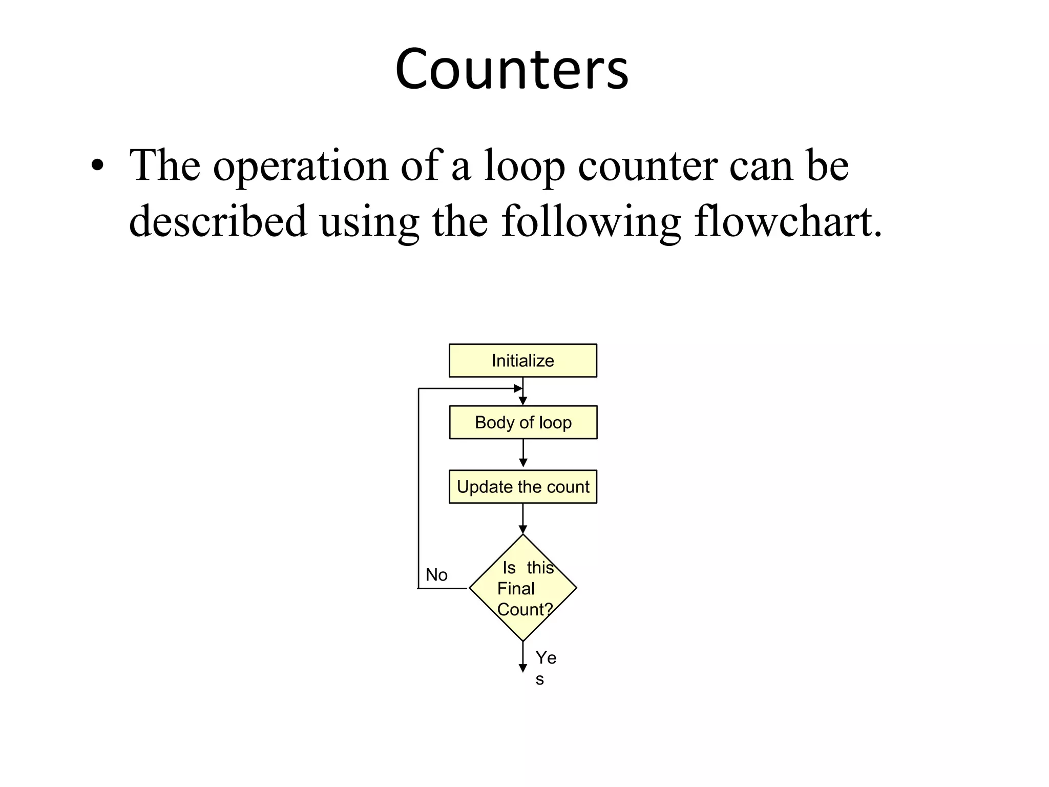
- Counters and time delays can be implemented using loops in assembly language. A loop counter is initialized and decremented/incremented at each iteration.
- Using a single register allows looping up to 255 times. A register pair can extend this by ORing the registers and checking the zero flag.
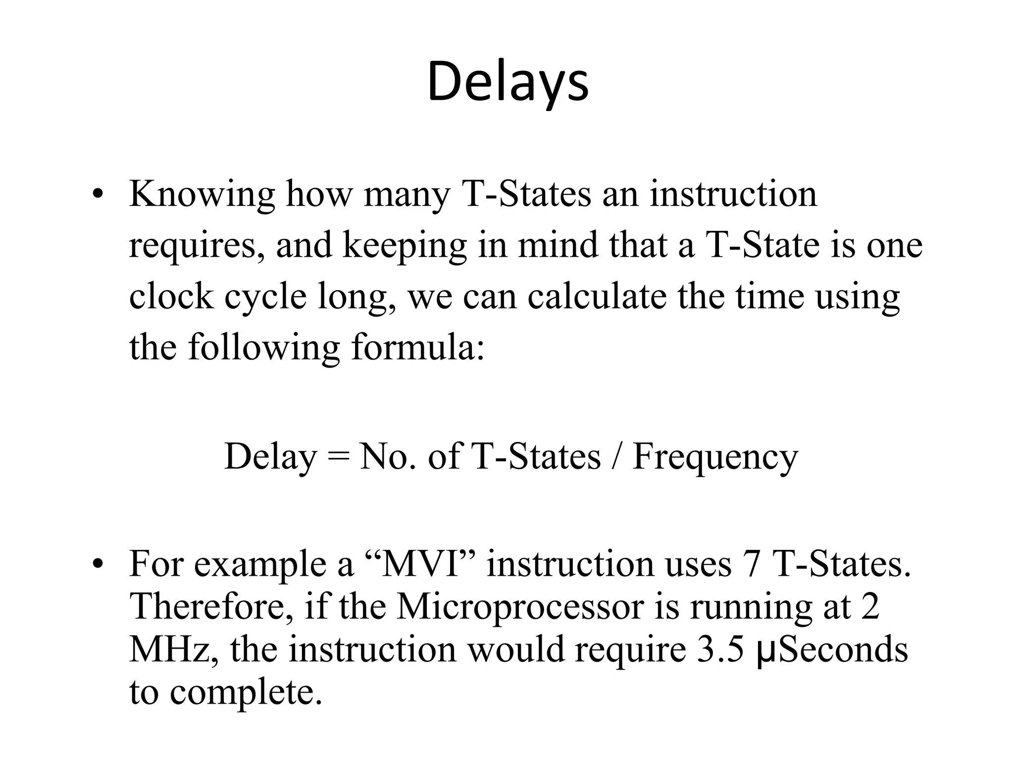
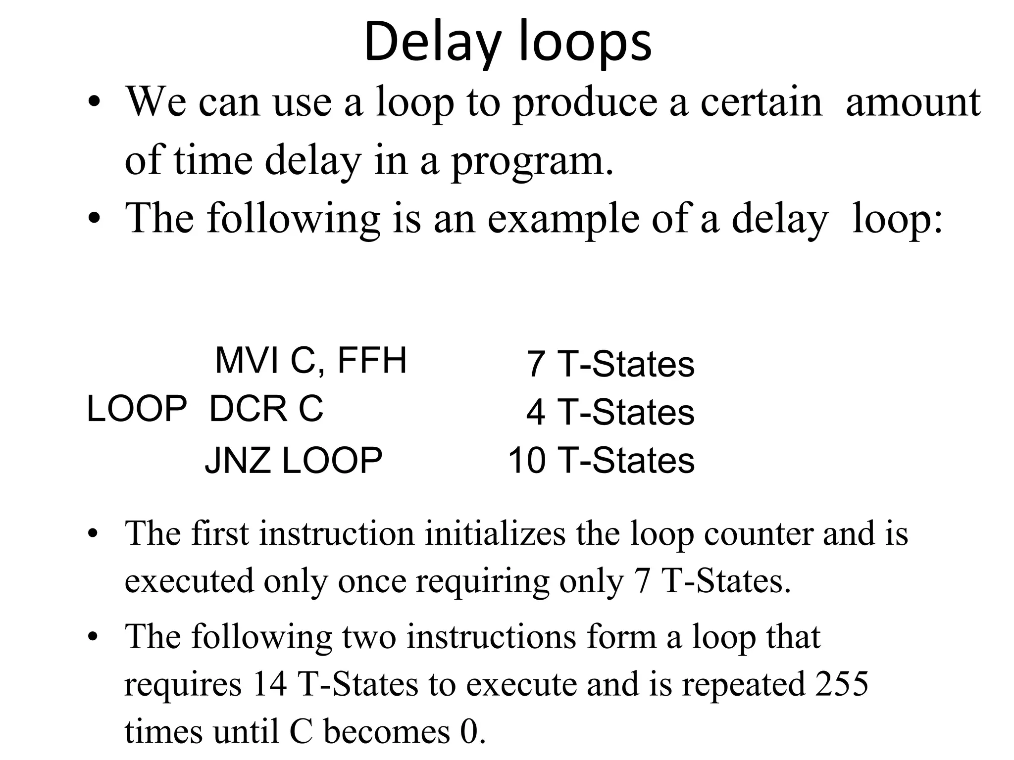
- Instruction timing is measured in T-states. Delay loops produce a timed delay by repeating instructions a set number of times.
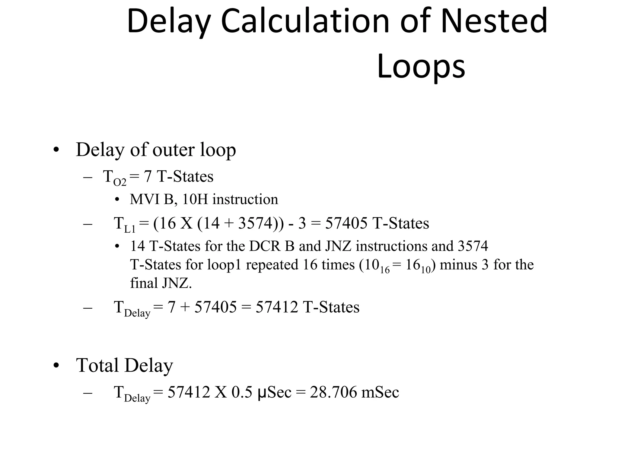
- Nested loops place one loop inside another to further increase delay time by repeating the inner loop multiple times.
2. Counters
• A loop counter is set up by loading a register with
a certain value
• Then using the DCR (to decrement) and INR (to
increment) the contents of the register are updated.
• A loop is set up with a conditional jump
instruction that loops back or not depending on
whether the count has reached the termination
count.
3. Counters
• The operation of a loop counter can be
described using the following flowchart.
Initialize
Update the count
Is this
Final
Count?
Body of loop
No
Ye
s
4. MVI C, 15H
LOOP DCR C
JNZ LOOP
Sample ALP for implementing a loop
Using DCR instruction
5. Using a Register Pair as a Loop
Counter
• Using a single register, one can repeat a loop
for a maximum count of 255 times.
• It is possible to increase this count by using a
register pair for the loop counter instead of the
single register.
– A minor problem arises in how to test for the final count
since DCX and INX do not modify the flags.
– However, if the loop is looking for when the count becomes
zero, we can use a small trick by ORing the two registers in
the pair and then checking the zero flag.
6. Using a Register Pair as a Loop
Counter
• The following is an example of a loop set
up with a register pair as the loop counter.
LXI B, 1000H
LOOP DCX B
MOV A, C
ORA B
JNZ LOOP
7. Delays
• It was shown in Chapter 2 that each instruction
passes through different combinations of Fetch,
Memory Read, and Memory Write cycles.
• Knowing the combinations of cycles, one can
calculate how long such an instruction would
require to complete.
• The table in Appendix F of the book contains a
column with the title B/M/T.
– B for Number of Bytes
– M for Number of Machine Cycles
– T for Number of T-State.
8. Delays
• Knowing how many T-States an instruction
requires, and keeping in mind that a T-State is one
clock cycle long, we can calculate the time using
the following formula:
Delay = No. of T-States / Frequency
• For example a “MVI” instruction uses 7 T-States.
Therefore, if the Microprocessor is running at 2
MHz, the instruction would require 3.5 μSeconds
to complete.
9. Delay loops
• We can use a loop to produce a certain amount
of time delay in a program.
• The following is an example of a delay loop:
MVI C, FFH
LOOP DCR C
JNZ LOOP
7 T-States
4 T-States
10 T-States
• The first instruction initializes the loop counter and is
executed only once requiring only 7 T-States.
• The following two instructions form a loop that
requires 14 T-States to execute and is repeated 255
times until C becomes 0.
10. Delay Loops (Contd.)
• We need to keep in mind though that in the last
iteration of the loop, the JNZ instruction will fail and
require only 7 T-States rather than the 10.
• Therefore, we must deduct 3 T-States from the total
delay to get an accurate delay calculation.
• To calculate the delay, we use the following formula:
Tdelay
= TO
+ TL
– Tdelay = total delay
– TO = delay outside the loop
– TL = delay of the loop
• TO is the sum of all delays outside the loop.
11. Delay Loops (Contd.)
• Using these formulas, we can calculate the
time delay for the previous example:
• TO = 7 T-States
– Delay of the MVI instruction
• TL = (14 X 255) - 3 = 3567 T-States
– 14 T-States for the 2 instructions repeated 255 times
(FF16 = 25510) reduced by the 3 T-States for the final
JNZ.
12. Using a Register Pair as a Loop
Counter
• Using a single register, one can repeat a loop
for a maximum count of 255 times.
• It is possible to increase this count by using a
register pair for the loop counter instead of the
single register.
– A minor problem arises in how to test for the final count
since DCX and INX do not modify the flags.
– However, if the loop is looking for when the count becomes
zero, we can use a small trick by ORing the two registers in
the pair and then checking the zero flag.
13. Using a Register Pair as a Loop
Counter
• The following is an example of a delay loop
set up with a register pair as the loop
counter.
LXI B, 1000H
LOOP DCX B
MOV A, C
ORA B
JNZ LOOP
10 T-States
6 T-States
4 T-States
4 T-States
10 T-States
14. Using a Register Pair as a Loop
Counter
• Using the same formula from before, we can
calculate:
• TO = 10 T-States
– The delay for the LXI instruction
• TL = (24 X 4096) - 3 = 98301 T- States
– 24 T-States for the 4 instructions in the loop repeated
4096 times (100016 = 409610) reduced by the 3 T-
States for the JNZ in the last iteration.
15. Nested Loops
• Nested loops can be
easily setup in
Assembly language by
using two registers for
the two loop counters
and updating the right
register in the right
loop.
• –In the figure, the body of
loop2 can be before or
after loop1.
Update the count1
Is this
Final
Count?
Initialize loop 1
Body of loop 1
No
Ye
s
Initialize loop 2
Body of loop 2
Update the count 2
Is this
Final
Count?
No
Ye
s
16. Nested Loops for Delay
• Instead (or in conjunction with) Register Pairs, a
nested loop structure can be used to increase the
total delay produced.
MVI B, 10H 7 T-States
LOOP2 MVI C, FFH 7 T-States
LOOP1 DCR C 4 T-States
JNZ LOOP1 10 T-States
DCR B 4 T-States
JNZ LOOP2 10 T-States
17. Delay Calculation of Nested
Loops
• The calculation remains the same except
that it the formula must be applied
recursively to each loop.
– Start with the inner loop, then plug that delay in
the calculation of the outer loop.
• Delay of inner loop
– TO1 = 7 T-States
• MVI C, FFH instruction
– TL1 = (255 X 14) - 3 = 3567 T-States
• 14 T-States for the DCR C and JNZ instructions repeated 255
times (FF = 255 ) minus 3 for the final JNZ
18. • Delay of outer loop
– TO2 = 7 T-States
• MVI B, 10H instruction
– TL1 = (16 X (14 + 3574)) - 3 = 57405 T-States
• 14 T-States for the DCR B and JNZ instructions and 3574
T-States for loop1 repeated 16 times (1016 = 1610) minus 3 for the
final JNZ.
– TDelay = 7 + 57405 = 57412 T-States
• Total Delay
– TDelay = 57412 X 0.5 μSec = 28.706 mSec
Delay Calculation of Nested
Loops
19. Increasing the delay
• The delay can be further increased by using
register pairs for each of the loop counters
in the nested loops setup.
• It can also be increased by adding dummy
instructions (like NOP) in the body of the
loop.