Downloaded 433 times

![Writing Time Delay Programs
6
8086 Microprocessor
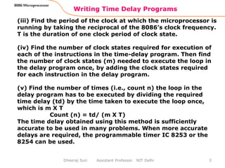
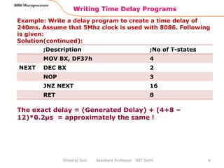
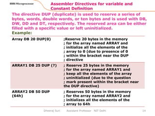
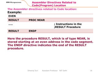
Example: Write a time delay program to generate a delay of
120ms in an 8086 – based system that runs on a 10Mhz
frequency clock.
Solution (continued):
The MOV BX, Count
& RET instructions in the delay program are executed only
once. The JNZ instruction takes 16 T-states when the
condition is satisfied (i.e. Z = 0) and four T – states when the
condition is not satisfied, which occurs only once.
Exact delay = [4 x 0.1 + (2+3) x 57143 x 0.1 + 16 x 57142
x0.1 + 4 X 0.1 + 8 X 0.1 ] µs
= 0.4 + 28571.5 + 91427.2 + 0.4 + 0.8
= 120000.3 µs = 120.0003 ms
The error in the previous calculation is very less as the exact
delay is also very close to 120ms. When 16-bit count register
is used in the delay program, the maximum count value that
can be loaded in it is FFFFh. This may put a limitation on the
maximum time delay that can be generated using the above
delay subroutine.
Dheeraj Suri Assistant Professor NIT Delhi](https://image.slidesharecdn.com/timedelayprogramsandassemblerdirectives8086-151117150554-lva1-app6891/85/Time-delay-programs-and-assembler-directives-8086-6-320.jpg)


![Other Assembler Directives
31
8086 Microprocessor
Dheeraj Suri Assistant Professor NIT Delhi
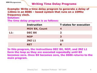
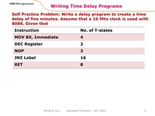
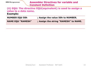
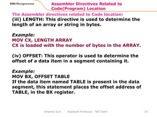
PTR The PTR(pointer) operator is used to declare the
type of label, variable, or memory operand.
Examples: INC BYTE PTR[SI]
;Increment the byte contents of the memory
location addressed by SI
INC WORD PTR [BX]
;Increment the word contents of the memory
location addressed by BX
GLOBAL The labels, variables, constants, or procedures
declared GLOBAL may be used by other modules
of the program.
Example: GLOBAL DATA1, DATA2, ARRAY1
; above statement declares the variables DATA1,
; DATA2, and ARRAY1 as GLOBAL variables
LOCAL The label, variables, constants, or procedures
declared LOCAL in a module are to be used only
by that particular module.
Example: LOCAL DATA1, DATA2, ARRAY1, A1, A2](https://image.slidesharecdn.com/timedelayprogramsandassemblerdirectives8086-151117150554-lva1-app6891/85/Time-delay-programs-and-assembler-directives-8086-31-320.jpg)

![MACRO and ENDM
33
8086 Microprocessor
Dheeraj Suri Assistant Professor NIT Delhi
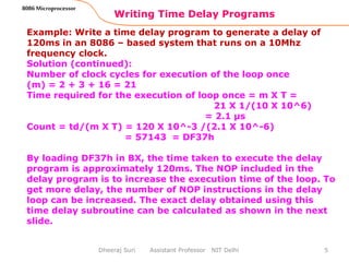
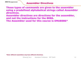
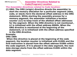
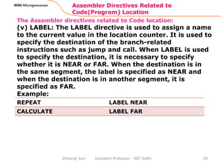
; Defining a MACRO
CALCULATE MACRO
MOV AX, [BX]
ADD AX, [BX + 2]
MOV [SI], AX
ENDM
; CALCULATE is the macro name and the macro is used to add two
successive data in the memory, whose offset address is present in
BX and the result is stored in the memory at the offset address in
SI.
Suppose a number of instructions occur repeatedly in the
main program, the program listing becomes lengthy. In such
a situation, a macro definition, i.e. a label, is assigned with
the repeatedly appearing string of instructions. The process
of assigning a label or macro name to the repeatedly
appearing string of instructions is called macro definition.
The macro name is then used throughout the main program
to refer to that string of instructions.](https://image.slidesharecdn.com/timedelayprogramsandassemblerdirectives8086-151117150554-lva1-app6891/85/Time-delay-programs-and-assembler-directives-8086-33-320.jpg)
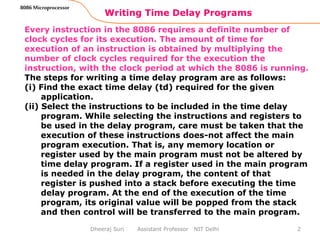
![Passing parameters to a MACRO
34
8086 Microprocessor
Dheeraj Suri Assistant Professor NIT Delhi
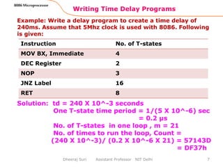
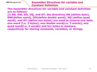
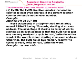
CALCULATE MACRO OPERAND, RESULT
MOV BX, OFFSET OPERAND
MOV AX, [BX]
ADD AX, [BX + 2]
MOV SI, OFFSET RESULT
MOV [SI], AX
ENDM
Using parameters in macro definition, the programmer
specifies the parameters of the macro that are likely to be
changed each time the macro is called. The macro given
before (CALCULATE) can be modified to calculate the result
for the different sets of data and store it in a different
memory locations as follows:](https://image.slidesharecdn.com/timedelayprogramsandassemblerdirectives8086-151117150554-lva1-app6891/85/Time-delay-programs-and-assembler-directives-8086-34-320.jpg)


![Example Programs (using Directives)
37
8086 Microprocessor
Dheeraj Suri Assistant Professor NIT Delhi
1. Program to find the average of 10 byte-type data stored in
an array in data segment (continued).
NEXT: MOV BL, [SI] ; Move one byte
; from array into
BL
ADD AX, BX ; Add AX and BX
INC SI ; Increment SI to
point to next byte
LOOP NEXT ; Repeat Loop
; NEXT CX times
MOV DH, COUNT ; MOV Count to DH
DIV DH ;Divide AX by CH
MOV AVERAGE, AL ; Store AL contents
; in AVERAGE
CODE1 ENDS ;Code Segment
ends](https://image.slidesharecdn.com/timedelayprogramsandassemblerdirectives8086-151117150554-lva1-app6891/85/Time-delay-programs-and-assembler-directives-8086-37-320.jpg)


The document provides a detailed explanation of writing time delay programs using the 8086 microprocessor, including how to calculate clock periods and the required number of executions for loops. It also covers assembler directives for defining variables, constants, and segment declarations, and how these directives guide the assembler in converting assembly language code to machine code. Several examples demonstrate creating time delays and using assembler directives effectively in 8086 programming.