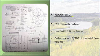
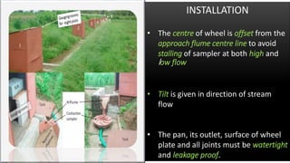
• Developed by W. H. Pomerence of N.
Appalachian Experimental Watershed
Coshocton, Ohio, U. S. A
• Tested and standardized by Donald
A. Parsons (1954).
• Standardized design have been
developed by Parson for samplers of
diameter of 1, 2, 3 ft. and are
designed as Model N-1, N-2, and
N-3 respectively
• Model N-1 _
• 1 foot diameter wheel
• Used with ½ ft. H-Flume.
• It collects about 1/100 of total
volume of flow.
COVER PAGE
• Model N-2 _
• 2 ft. diameter wheel.
• Used with 1 ft. H- flume.
• Collects about 1/200 of the total flow
volume
• Model N-3 _
• 3 ft. diameter wheel.
• Used with 1.5 ft. H- flume.
• Collects about 1/300 of the total
flow volume
SLOT
Parts of Coshocton wheel
sampler:
• H -flume
• Sampling head
• Wheel plate
• Turning vanes
• Collecting pan
• Base plate
• Outlet
INSTALLATION
• The centre of wheel is offset from the
approach flume centre line to avoid
stalling of sampler at both high and
low flow
• Tilt is given in direction of stream
flow
• The pan, its outlet, surface of wheel
plate and all joints must be watertight
and leakage proof.
Performance of Sampler
• Upto 80% of flume capacity, the runoff
sampling error was within 5% limit.
• Error increased with higher rate of flow.
• The coarse sediment mixture when
introduced in the flume gives different
result then fine sediment mixture in the
steam
• Carter and Parson carried out field tests
and modified the slot width for better
performance
STORAGE TANK
• Required size of tank can be estimated by
considering size of plot, expected max
rainfall in 24 hours.
• Provisions for 1/100, 1/200, 1/300 of
maximum total runoff volume expected in
24 hours will be provided for model N-1,
N-2 & N-3 respectively.
• If the size of storage tank works out to be
too high, the volume of sample can be
further reduced by using multislot divisor.
LIMITATIONS
• The bearing of the wheel need to be
kept clean & properly greased
• Frequent inspections during flow
• Each model of sampler should be used
with corresponding H- flume
H- Type Flumes
• Developed and calibrated in the hydraulic
laboratory by the Soil Conservation Service,
USDA for measurement of runoff from
small areas.
• The vertical sides of the flume are
converging and are cut back on a slope from
the outlet to give a trapezoidal throat
opening which increases with the depth of
the flume
• The shape provides following advantages :
i. Accurate measurement of both high and
low flows
ii. Makes the flume self cleaning
iii. Simple construction, rigid, stable, last
maintenance
iv. Easy for installation
• Multi slot divisor is useful for
measuring runoff from small plots
• It is used to collect only a part of the
runoff into a masonry tank.
• Water samples from the tank are
taken and sediment quantity is
estimated from the samples.
• Mostly used for experiment purpose
PARTS OF MULTI-SLOT DIVISOR:
It having mainly 3 parts
A. Collection Tank
B. Slot Divisor
C. Cistern Tank
COLLECTION TANK
• The tank has 3- 4 compartments to
obtain greater depth for low flows.
• The dimensions of collection tank are
1.5m x 2m x 0.62m.
• Tank is provided with inclined lid to
prevent rainfall entrance.
• Tank should be constructed on level
surface.
• Should be fitted with taps to drain out
the stored water after measurement.
• Tank can be made of 16- 20 gauge galvanised
sheet metal with 3-4 feet dia or bricks and stone
masonry.
SLOT DIVISOR
• The slot divisor with 11 slots was
used for experimentation generally.
• It is always provided with the odd
number of slots and mid slot is slot
connected to the cistern tank.
• It is also covered with cap on it’s top.
SELECTION OF DIVISOR
• Selection will depend on the
expected runoff rate & ratio of
runoff to be stored in tank.
• The choice of the divisor is made
with regard to the capacity, number
of slot, width and length of slots.
• No. of slots, 𝑵 =
𝟏𝟎𝟎 𝑨𝑷𝑭
𝑪
.
where, A = plot area (𝑚2)
P = Precipitation depth (mm)
F = expected max runoff percentage (%)
Cistern Tank (circular drum)
• It is cylindrical shaped with a lid
provided to the tank
• The hole is closed using rubber cork.
• It is installed at height of 5-10 cm
from ground to avoid corrosion.
• It is connected with the slot divisor.
• The capacity of drum is 500 litres
with radius of 0.42 m and height of
0.90 m.
INSTALLATION
• To conduct this experiment a particular
place with a slope of 60% and 90% was
selected.
• After making the area into slopes of 60%
and 90%,the soil was compressed to be firm
• After compacting plot area it was separated
into 4 plots
• The dimensions of plots are 15m x 4m in
both the 60% and 90% slopes.
Continued..
60% slope 90%
slope
60% slope 90%
slope
INSTALLATION
• The GI sheets acts as a boundary
walls separating the plots and
protecting soil from erosion.
• The runoff collection channels were
constructed for each plot to collect
runoff.
• Plots and pipes are provided to
convey runoff water into tank for
both 60% and 90% slopes.
• The collection channel is
constructed of bricks using cement
of 35cm height.
Continued..
Runoff tank Installation Mult-slot
attached
INSTALLATION
• Below the collection channel 30cm
basement is provided to stabilize
the channel.
• The pit was made of size 3.6m x
1.4m to install runoff tank.
• The cistern tank was also installed in
this pit by extending the length of
the pit.
• The collection tank installed in the
pit it is divided into 4
compartments
• Then runoff tank is connected with
slot divisor to collect excess runoff
into cistern tank
Construction of runoff channels
Runoff water collection
• The runoff water collected in the
compartments is calculated by
measuring the height of water
present.
• Then the runoff water is stirred well
in the tank itself, so that the soil gets
distributed uniformly in water.
• Then runoff water is filled into two
bottles of one litre each.
• Then these bottles are handed over
in lab for analysis of soil loss.
Measuring height of runoff water
Runoff volume & Soil loss Calculation
• The runoff water collected in the
tank is measured in the form of
volume.
• i.e. V = L x B x H
• Runoff = Volume/area
• Volume(m³)= πr²h
where, r = Radius of cistern tank
h = Height of water in cistern tank
Stirring of runoff water
Soil loss Estimation
Collect sample runoff water
Keep it for 24 hours aside
Remove water from bottle
Keep soil for 24 hrs at 1000𝑐 in oven dryer
Take dry weight of soil
• 𝑆𝑂𝐼𝐿 𝐿𝑂𝑆𝑆
𝑘𝑔
ℎ𝑎
= 𝑅𝑢𝑛𝑜𝑓𝑓 (𝑙𝑖𝑡) 𝑥 𝑆𝑜𝑖𝑙 𝑙𝑜𝑠𝑠(𝑘𝑔/𝑙𝑖𝑡) 𝑥 (10000/60)
USE
• Simple in construction and function,
neither has any moving parts, nor
needs use of stage level recorder.
• Standard multi-slot divisor can be
used for measurement of runoff
volume and sediment yield upto 4
cusec i.e. approx. ½ acre car
ADVANTAGES
• Simple in design and operation.
• No risk of mechanical failure.
• Data reduction and processing are
relatively simple.
LIMITATIONS
• Cost of installation and operation is
relatively high.
• Use is limited to runoff volume
only.
• Higher capacity tank is required.
Coshocton wheel

Coshocton wheel

  • 2.
    • Developed byW. H. Pomerence of N. Appalachian Experimental Watershed Coshocton, Ohio, U. S. A • Tested and standardized by Donald A. Parsons (1954). • Standardized design have been developed by Parson for samplers of diameter of 1, 2, 3 ft. and are designed as Model N-1, N-2, and N-3 respectively
  • 3.
    • Model N-1_ • 1 foot diameter wheel • Used with ½ ft. H-Flume. • It collects about 1/100 of total volume of flow. COVER PAGE
  • 4.
    • Model N-2_ • 2 ft. diameter wheel. • Used with 1 ft. H- flume. • Collects about 1/200 of the total flow volume
  • 5.
    • Model N-3_ • 3 ft. diameter wheel. • Used with 1.5 ft. H- flume. • Collects about 1/300 of the total flow volume
  • 6.
  • 7.
    Parts of Coshoctonwheel sampler: • H -flume • Sampling head • Wheel plate • Turning vanes • Collecting pan • Base plate • Outlet
  • 8.
    INSTALLATION • The centreof wheel is offset from the approach flume centre line to avoid stalling of sampler at both high and low flow • Tilt is given in direction of stream flow • The pan, its outlet, surface of wheel plate and all joints must be watertight and leakage proof.
  • 9.
    Performance of Sampler •Upto 80% of flume capacity, the runoff sampling error was within 5% limit. • Error increased with higher rate of flow. • The coarse sediment mixture when introduced in the flume gives different result then fine sediment mixture in the steam • Carter and Parson carried out field tests and modified the slot width for better performance
  • 10.
    STORAGE TANK • Requiredsize of tank can be estimated by considering size of plot, expected max rainfall in 24 hours. • Provisions for 1/100, 1/200, 1/300 of maximum total runoff volume expected in 24 hours will be provided for model N-1, N-2 & N-3 respectively. • If the size of storage tank works out to be too high, the volume of sample can be further reduced by using multislot divisor.
  • 12.
    LIMITATIONS • The bearingof the wheel need to be kept clean & properly greased • Frequent inspections during flow • Each model of sampler should be used with corresponding H- flume
  • 13.
    H- Type Flumes •Developed and calibrated in the hydraulic laboratory by the Soil Conservation Service, USDA for measurement of runoff from small areas. • The vertical sides of the flume are converging and are cut back on a slope from the outlet to give a trapezoidal throat opening which increases with the depth of the flume • The shape provides following advantages : i. Accurate measurement of both high and low flows ii. Makes the flume self cleaning iii. Simple construction, rigid, stable, last maintenance iv. Easy for installation
  • 15.
    • Multi slotdivisor is useful for measuring runoff from small plots • It is used to collect only a part of the runoff into a masonry tank. • Water samples from the tank are taken and sediment quantity is estimated from the samples. • Mostly used for experiment purpose
  • 16.
    PARTS OF MULTI-SLOTDIVISOR: It having mainly 3 parts A. Collection Tank B. Slot Divisor C. Cistern Tank
  • 17.
    COLLECTION TANK • Thetank has 3- 4 compartments to obtain greater depth for low flows. • The dimensions of collection tank are 1.5m x 2m x 0.62m. • Tank is provided with inclined lid to prevent rainfall entrance. • Tank should be constructed on level surface. • Should be fitted with taps to drain out the stored water after measurement. • Tank can be made of 16- 20 gauge galvanised sheet metal with 3-4 feet dia or bricks and stone masonry.
  • 18.
    SLOT DIVISOR • Theslot divisor with 11 slots was used for experimentation generally. • It is always provided with the odd number of slots and mid slot is slot connected to the cistern tank. • It is also covered with cap on it’s top.
  • 19.
    SELECTION OF DIVISOR •Selection will depend on the expected runoff rate & ratio of runoff to be stored in tank. • The choice of the divisor is made with regard to the capacity, number of slot, width and length of slots. • No. of slots, 𝑵 = 𝟏𝟎𝟎 𝑨𝑷𝑭 𝑪 . where, A = plot area (𝑚2) P = Precipitation depth (mm) F = expected max runoff percentage (%)
  • 20.
    Cistern Tank (circulardrum) • It is cylindrical shaped with a lid provided to the tank • The hole is closed using rubber cork. • It is installed at height of 5-10 cm from ground to avoid corrosion. • It is connected with the slot divisor. • The capacity of drum is 500 litres with radius of 0.42 m and height of 0.90 m.
  • 21.
    INSTALLATION • To conductthis experiment a particular place with a slope of 60% and 90% was selected. • After making the area into slopes of 60% and 90%,the soil was compressed to be firm • After compacting plot area it was separated into 4 plots • The dimensions of plots are 15m x 4m in both the 60% and 90% slopes. Continued.. 60% slope 90% slope 60% slope 90% slope
  • 22.
    INSTALLATION • The GIsheets acts as a boundary walls separating the plots and protecting soil from erosion. • The runoff collection channels were constructed for each plot to collect runoff. • Plots and pipes are provided to convey runoff water into tank for both 60% and 90% slopes. • The collection channel is constructed of bricks using cement of 35cm height. Continued.. Runoff tank Installation Mult-slot attached
  • 23.
    INSTALLATION • Below thecollection channel 30cm basement is provided to stabilize the channel. • The pit was made of size 3.6m x 1.4m to install runoff tank. • The cistern tank was also installed in this pit by extending the length of the pit. • The collection tank installed in the pit it is divided into 4 compartments • Then runoff tank is connected with slot divisor to collect excess runoff into cistern tank Construction of runoff channels
  • 24.
    Runoff water collection •The runoff water collected in the compartments is calculated by measuring the height of water present. • Then the runoff water is stirred well in the tank itself, so that the soil gets distributed uniformly in water. • Then runoff water is filled into two bottles of one litre each. • Then these bottles are handed over in lab for analysis of soil loss. Measuring height of runoff water
  • 25.
    Runoff volume &Soil loss Calculation • The runoff water collected in the tank is measured in the form of volume. • i.e. V = L x B x H • Runoff = Volume/area • Volume(m³)= πr²h where, r = Radius of cistern tank h = Height of water in cistern tank Stirring of runoff water
  • 26.
    Soil loss Estimation Collectsample runoff water Keep it for 24 hours aside Remove water from bottle Keep soil for 24 hrs at 1000𝑐 in oven dryer Take dry weight of soil • 𝑆𝑂𝐼𝐿 𝐿𝑂𝑆𝑆 𝑘𝑔 ℎ𝑎 = 𝑅𝑢𝑛𝑜𝑓𝑓 (𝑙𝑖𝑡) 𝑥 𝑆𝑜𝑖𝑙 𝑙𝑜𝑠𝑠(𝑘𝑔/𝑙𝑖𝑡) 𝑥 (10000/60) USE • Simple in construction and function, neither has any moving parts, nor needs use of stage level recorder. • Standard multi-slot divisor can be used for measurement of runoff volume and sediment yield upto 4 cusec i.e. approx. ½ acre car
  • 27.
    ADVANTAGES • Simple indesign and operation. • No risk of mechanical failure. • Data reduction and processing are relatively simple. LIMITATIONS • Cost of installation and operation is relatively high. • Use is limited to runoff volume only. • Higher capacity tank is required.