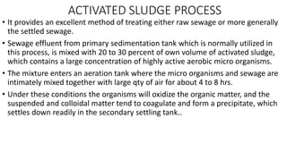
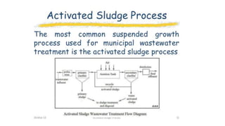
- The activated sludge process treats sewage by mixing it with activated sludge microorganisms in an aeration tank. This allows the microorganisms to break down organic matter over 4-8 hours. Effluent from this process has low BOD and high removal of bacteria and organic matter.
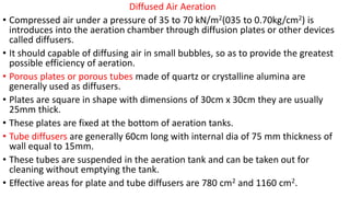
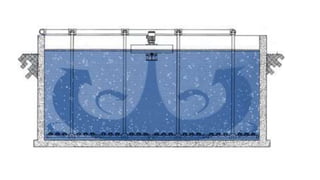
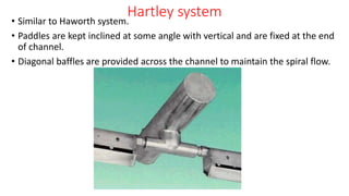
- Sewage is aerated in the tank through diffused air, mechanical aeration like paddles, or a combination. This provides oxygen for the microorganisms. Common methods include diffused air through plates or tubes, mechanical systems like Haworth and Simplex, or combined aeration.
- Filters like contact beds and intermittent sand filters further treat effluent through biological filtration in the media, removing additional organic