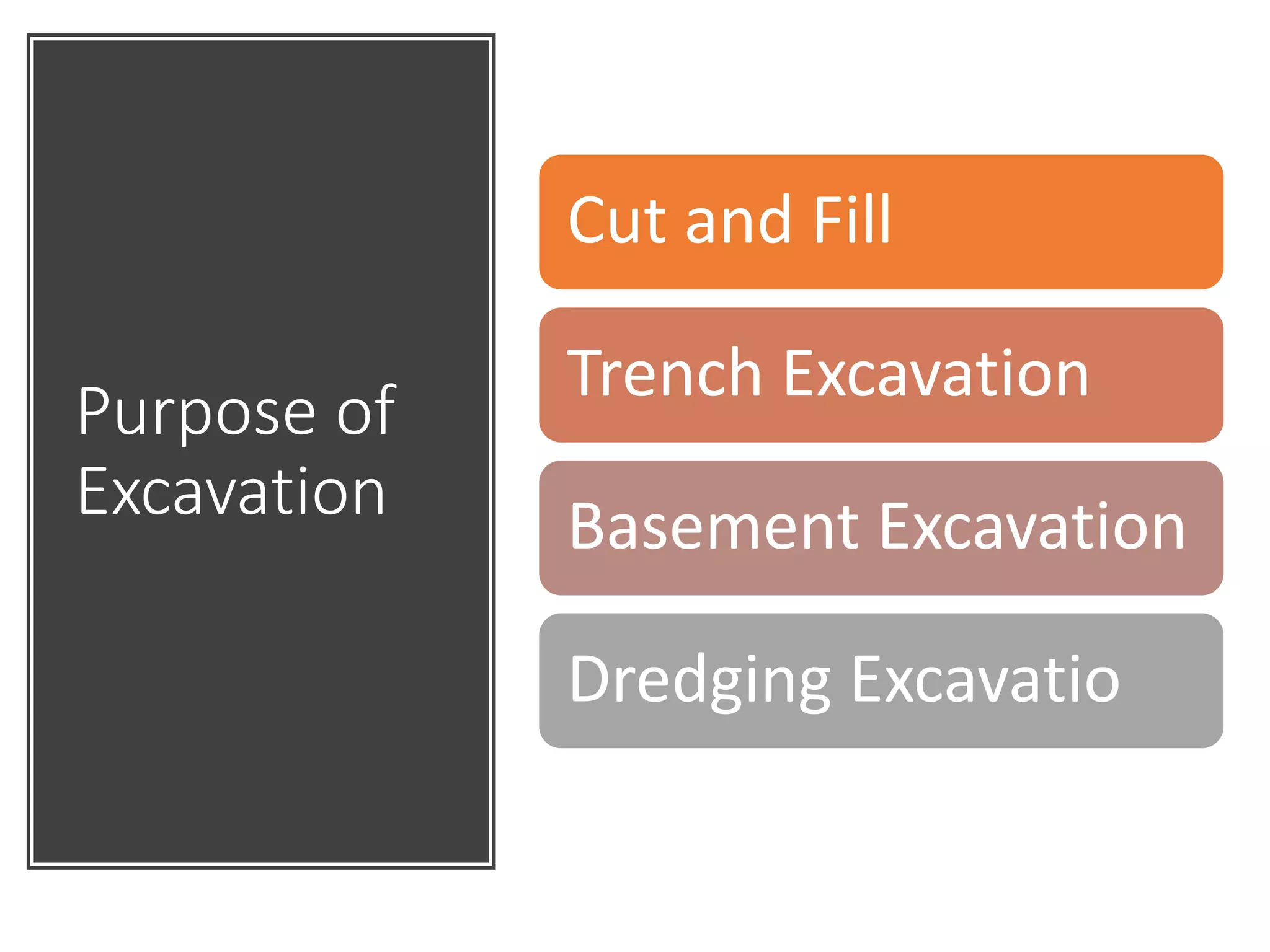
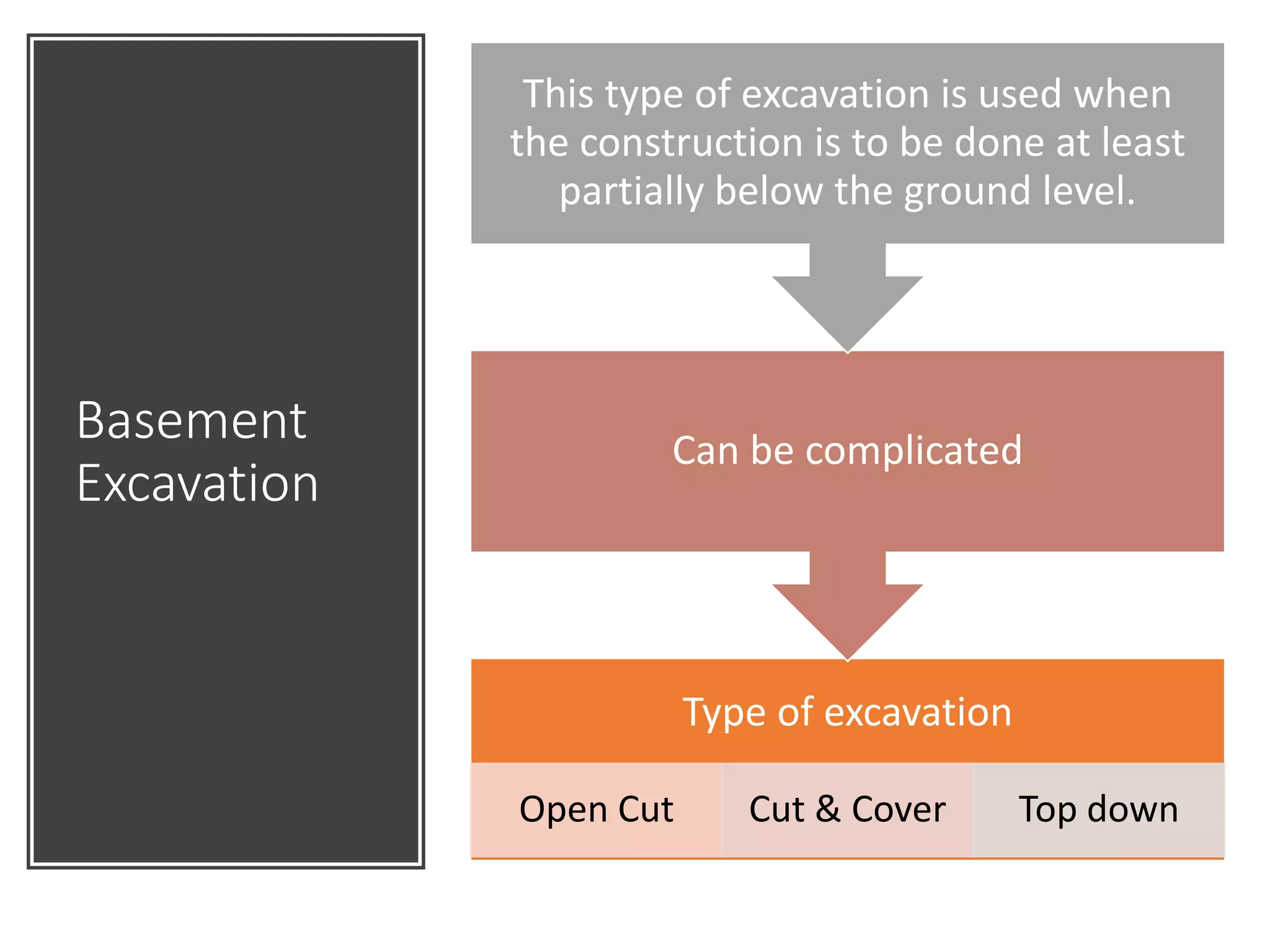
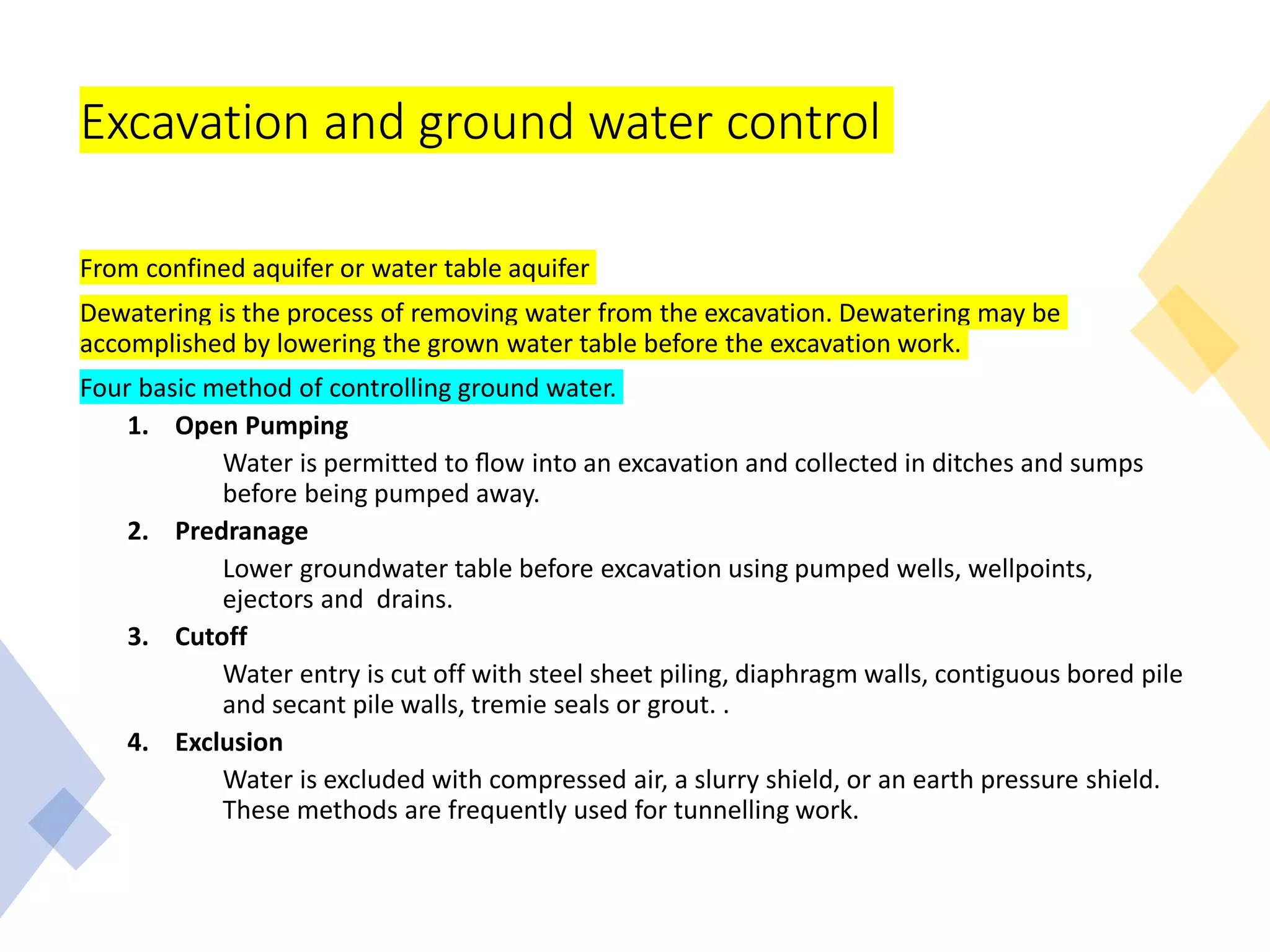
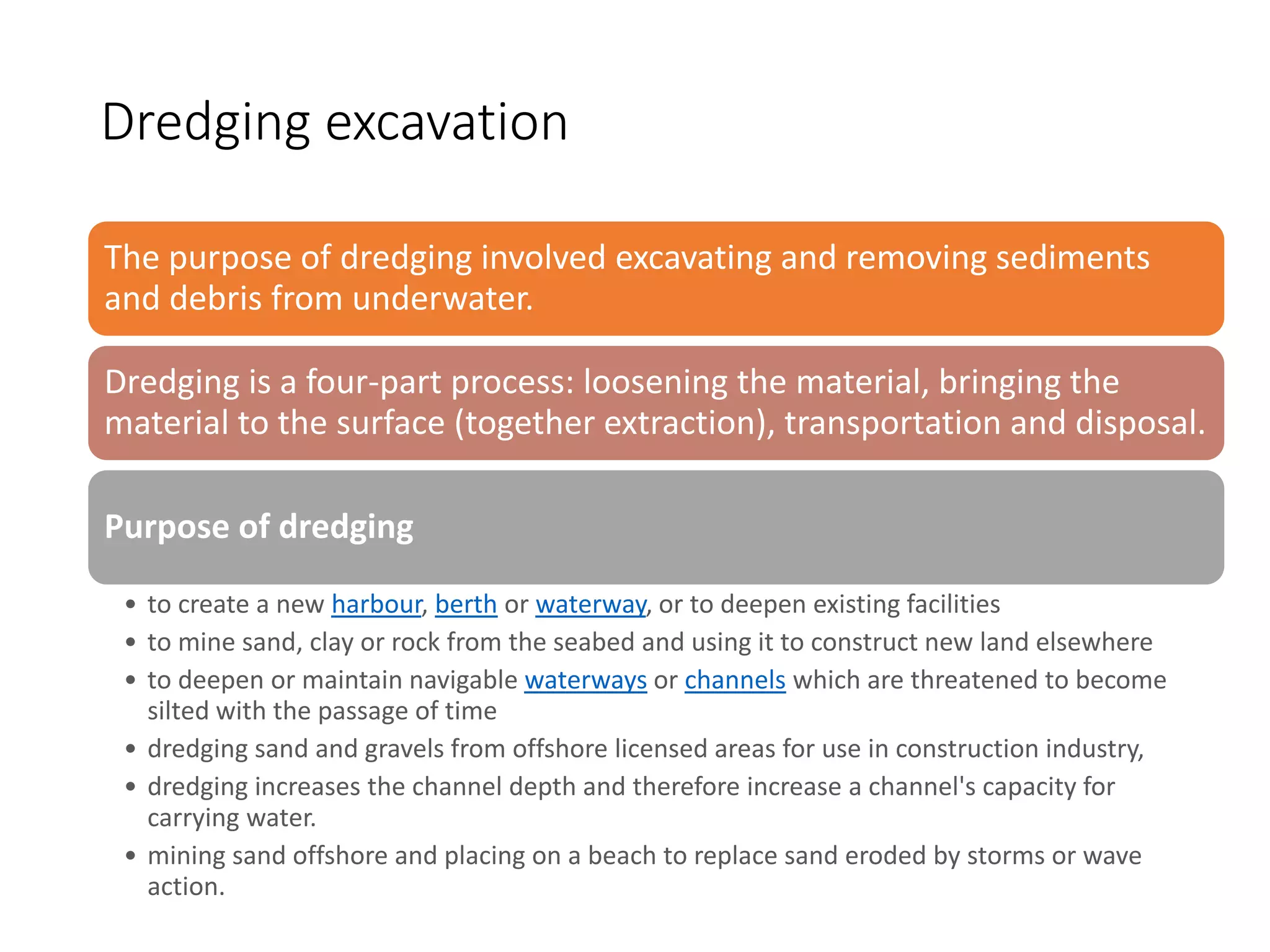
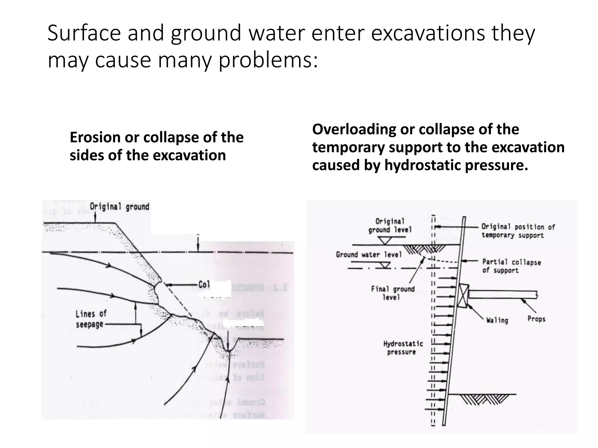
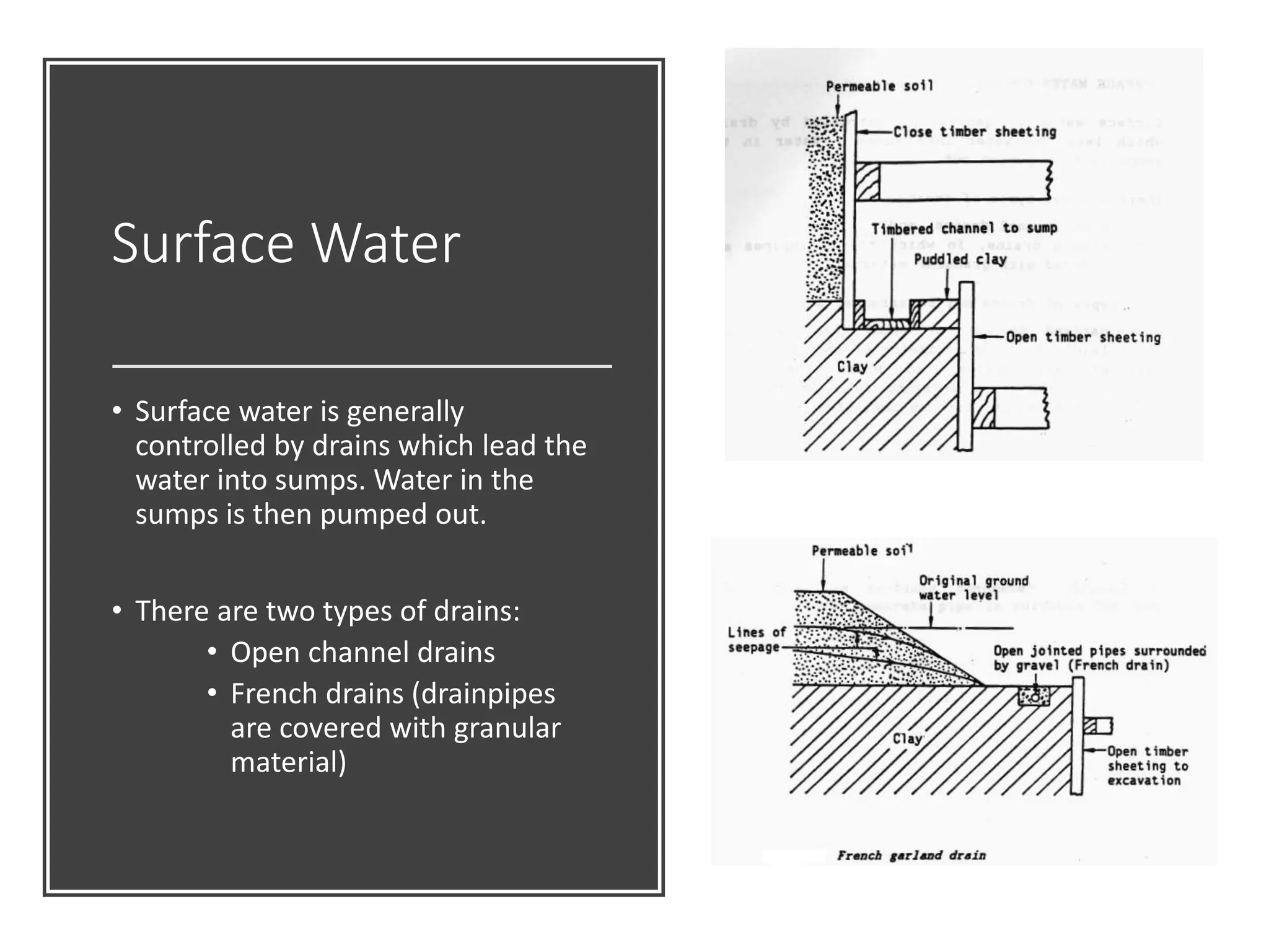
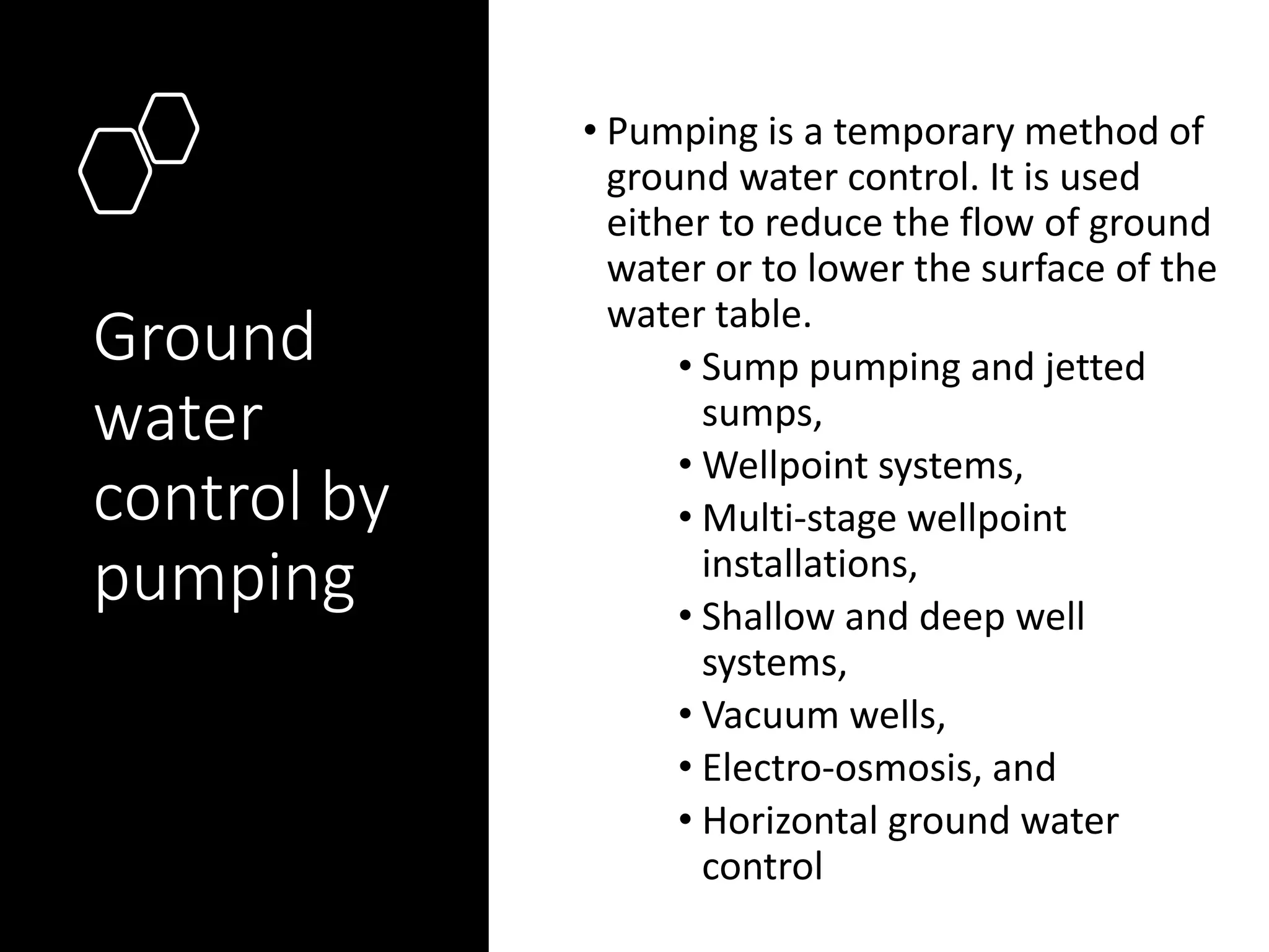
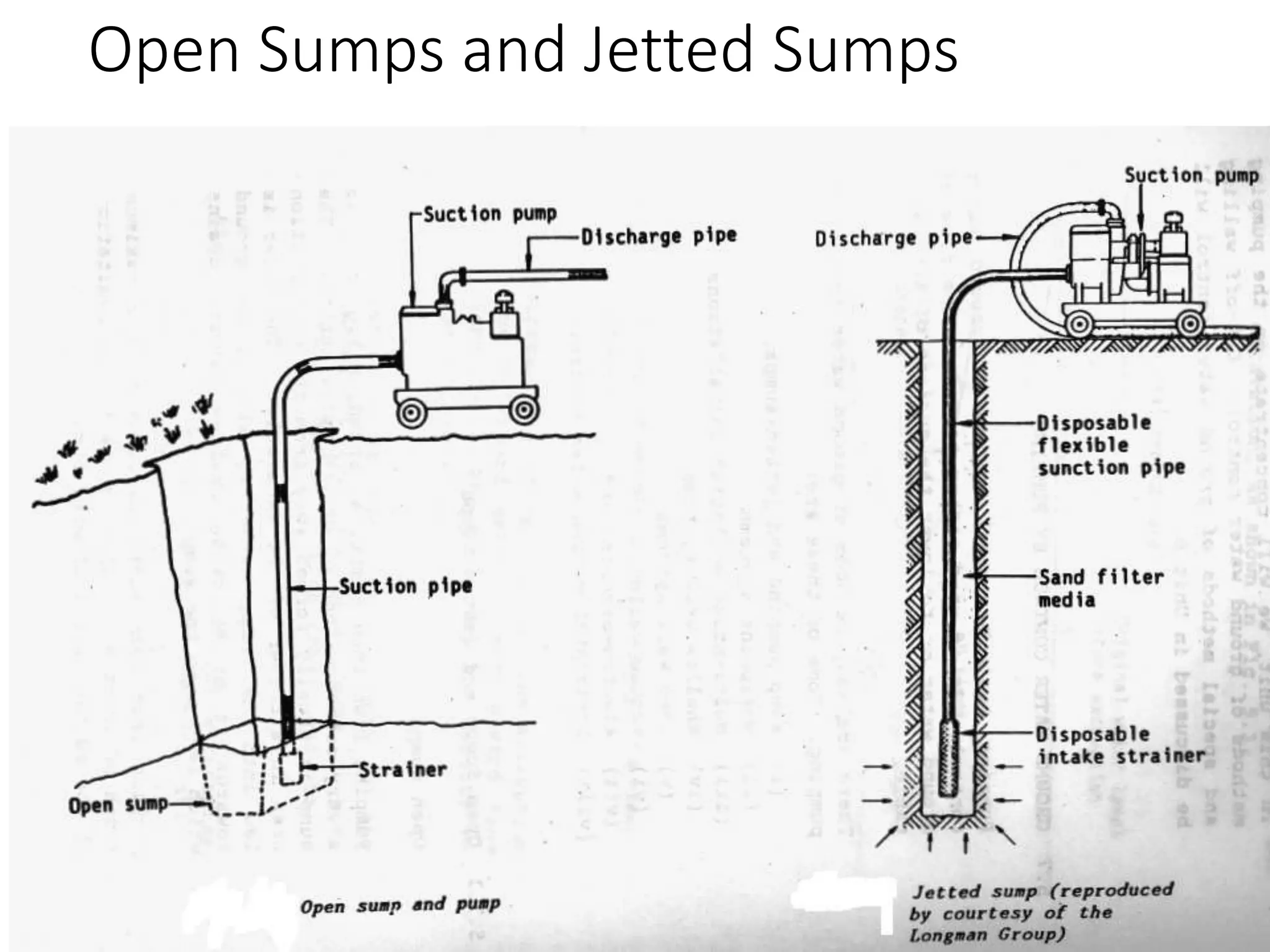
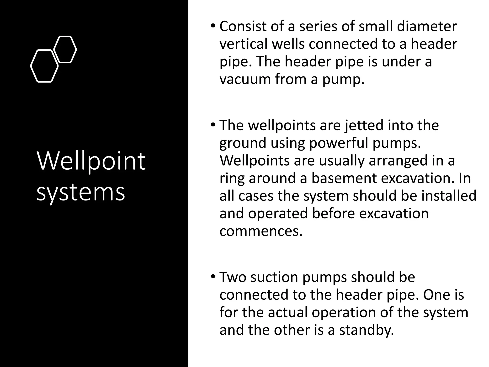
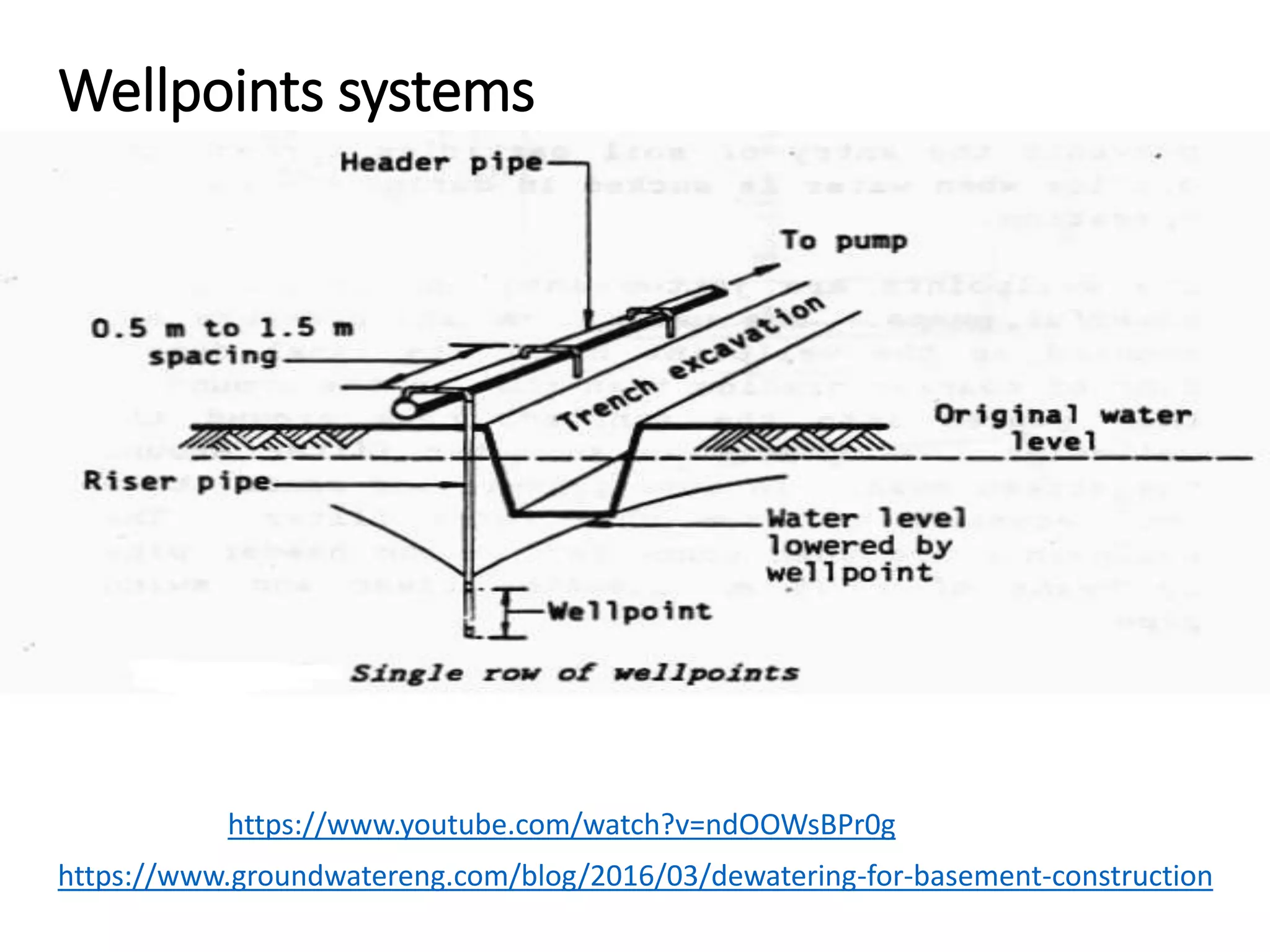
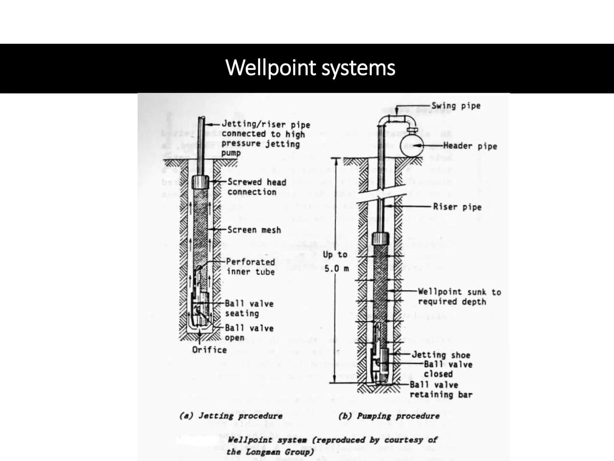
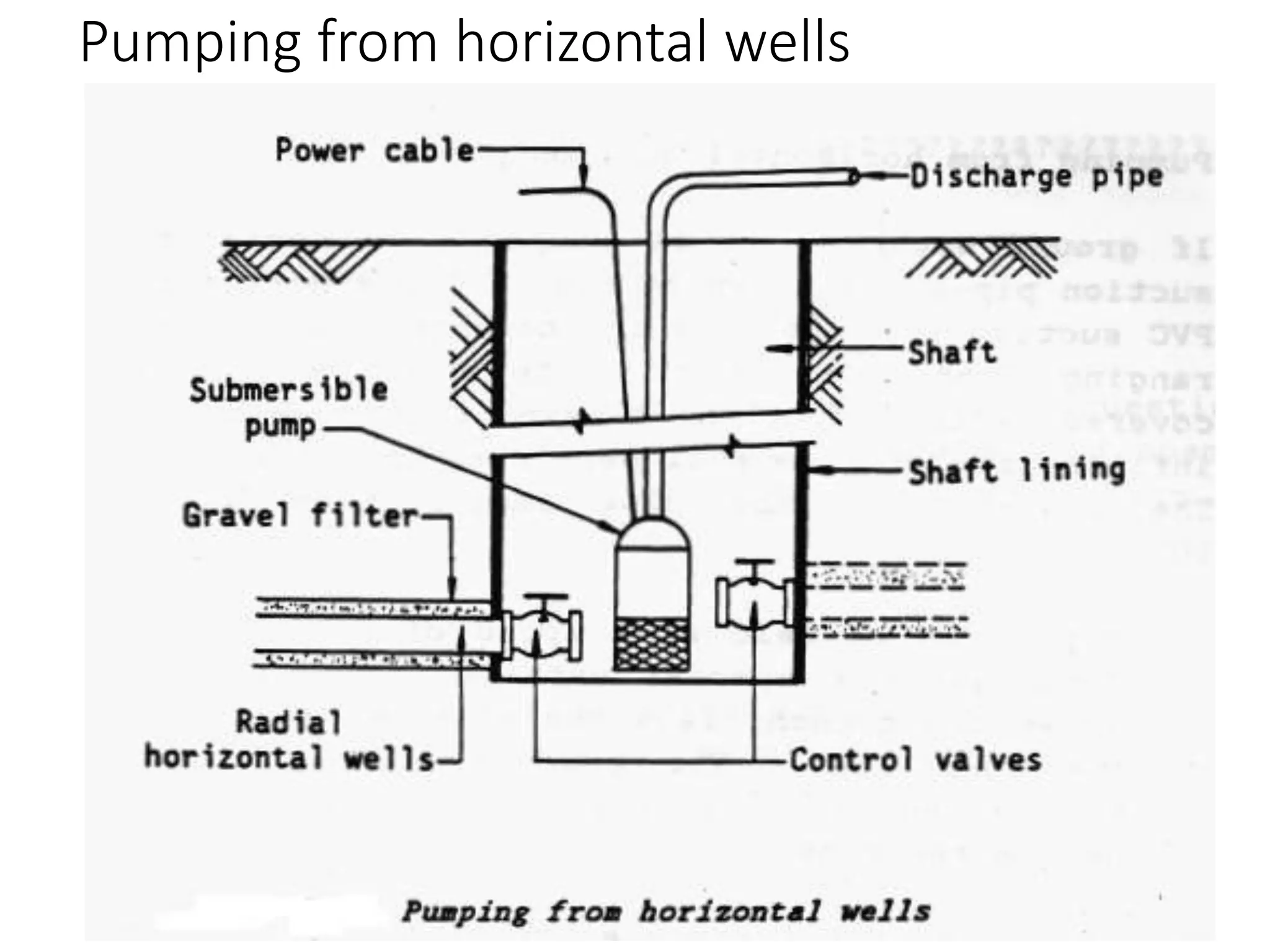
Excavation
Dr Lesly Ekanayake
Type of
Excavation
Topsoil Excavation
• Vegetation
• Soil
• Decaying materials
Rock Excavation
• Special equipment
• Drilling or blasting
Muck Excavation
• Combination of soil and water
Earth Excavation
• Create a foundation for buildings,
bridges, drainages
• Removal of soil
Purpose of
Excavation
Cut and Fill
Trench Excavation
Basement Excavation
Dredging Excavatio
Cut And Fill
Excavation
Used to clear large area
Grading the land
Amount of materials from Cuts roughly
matches of Fill
Cut and Fill drawings
Earthwork estimation software
automatically balance cut and fill
volume
Trench
Excavation
A human made narrow surface cavity that is
deeper than its width and bottom is less than
15ft wide
Service lines/ pipeline and sewer systems
Ground condition/ ground water and instability
of soil/ obstructions
Sloping side to a safe angle
Shoring system
Trench support system
Basement
Excavation
Type of excavation
Open Cut Cut & Cover Top down
Can be complicated
This type of excavation is used when
the construction is to be done at least
partially below the ground level.
Basement
Excavation
Shoring system
Sheet piling
Reinforced concrete
diaphragm wall
Contiguous bored
piles or secant piles.
Shoring should be provided for any
excavation that is more than 1.8m deep.
Adequately supported and ground water
properly controlled.
Excavation and ground water control
From confined aquifer or water table aquifer
Dewatering is the process of removing water from the excavation. Dewatering may be
accomplished by lowering the grown water table before the excavation work.
Four basic method of controlling ground water.
1. Open Pumping
Water is permitted to flow into an excavation and collected in ditches and sumps
before being pumped away.
2. Predranage
Lower groundwater table before excavation using pumped wells, wellpoints,
ejectors and drains.
3. Cutoff
Water entry is cut off with steel sheet piling, diaphragm walls, contiguous bored pile
and secant pile walls, tremie seals or grout. .
4. Exclusion
Water is excluded with compressed air, a slurry shield, or an earth pressure shield.
These methods are frequently used for tunnelling work.
The principal factors which affect the choice
of the appropriate dewatering techniques
The soil within
which the
excavation is to be
take place
The size of the
excavation
(available space)
The depth of
groundwater
lowering
The flow into the
excavation
Proposed method of
excavation
Proximity of existing
structures and their
depths and types of
foundation.
Economic
consideration.
Dredging excavation
The purpose of dredging involved excavating and removing sediments
and debris from underwater.
Dredging is a four-part process: loosening the material, bringing the
material to the surface (together extraction), transportation and disposal.
Purpose of dredging
• to create a new harbour, berth or waterway, or to deepen existing facilities
• to mine sand, clay or rock from the seabed and using it to construct new land elsewhere
• to deepen or maintain navigable waterways or channels which are threatened to become
silted with the passage of time
• dredging sand and gravels from offshore licensed areas for use in construction industry,
• dredging increases the channel depth and therefore increase a channel's capacity for
carrying water.
• mining sand offshore and placing on a beach to replace sand eroded by storms or wave
action.
Ground and Surface water
control in excavation
Open and Predranage Pumping
Cut-off walling
Special methods
Surface and ground water enter excavations they
may cause many problems:
Erosion or collapse of the
sides of the excavation
Overloading or collapse of the
temporary support to the excavation
caused by hydrostatic pressure.
Surface Water
• Surface water is generally
controlled by drains which lead the
water into sumps. Water in the
sumps is then pumped out.
• There are two types of drains:
• Open channel drains
• French drains (drainpipes
are covered with granular
material)
Ground water control
by
pumping
Ground water control
Ground
water
control by
pumping
• Pumping is a temporary method of
ground water control. It is used
either to reduce the flow of ground
water or to lower the surface of the
water table.
• Sump pumping and jetted
sumps,
• Wellpoint systems,
• Multi-stage wellpoint
installations,
• Shallow and deep well
systems,
• Vacuum wells,
• Electro-osmosis, and
• Horizontal ground water
control
Open Sumps and Jetted Sumps
• The open sump is usually formed away from the
construction area in a corner of the excavation. The water
is led into the sump, either by slopping the ground
towards it or by using shallow garland drains which fed
into the sump.
• Maximum depth is due to the limitation of the suction lifts
of most pumps.
• The jetted sump is formed in the ground by jetting a metal
tube. A disposable intake strainer connected disposable
flexible suction pipe is then lowered into the whole, and
void filled with sand filter media. This suction pipe is then
connected to a pump which pumps out the ground water.
Open Sumps and Jetted Sumps
Wellpoint
systems
• Consist of a series of small diameter
vertical wells connected to a header
pipe. The header pipe is under a
vacuum from a pump.
• The wellpoints are jetted into the
ground using powerful pumps.
Wellpoints are usually arranged in a
ring around a basement excavation. In
all cases the system should be installed
and operated before excavation
commences.
• Two suction pumps should be
connected to the header pipe. One is
for the actual operation of the system
and the other is a standby.
Wellpoints systems
https://www.youtube.com/watch?v=ndOOWsBPr0g
https://www.groundwatereng.com/blog/2016/03/dewatering-for-basement-construction
Wellpoint systems
Multi-stage Wellpoints
• Consist of the installation of wellpoints at two or more levels. This system is adopted if
the water table has to be lowered further than is possible by a normal wellpoint system.
• This second wellpoint system lowers the water table further, well below the formation
level.
Multi-
stage
Wellpoints
Shallow well systems
• Similar to wellpoint systems except that they can handle a greater volume of water.
• A well of diameter 300 mm or more is board to a depth of about 10 m (and lined with a
casing). A mesh-covered perforated filter tube of about 150 mm diameter is lowered into
the bore hole. The casing is gradually withdrawn during the placing of the filter media.
• A suction pipe is lowered into the filter tube and connected to the header main. The
header main is in turn connected to a self-priming pump.
• Multi-stage installations at two or more levels must be used for deep excavations.
Shallow well systems
Deep well Systems
• Deep well systems are an alternative to multi-stage systems. They are generally used
when the ground water has to be lowered by a depth of more than 9 m.
• In deep well system, an electrically powered submersible pump is lowered into the well
to a suitable depth to extract the water.
Deep well Systems
Vacuum wells
•If more than 10% silt present, it is necessary to
increase the water flow towards the wells.
•One method of artificially increasing the water flow
towards the wells is to create a vacuum inside the
perforated section of the filter tubes of the board
wells.
•To create this vacuum, the top of the well is sealed,
usually with clay, against the entry of air into the well.
Electro-osmosis
•This is another method of artificially increasing the water
flow towards the wells.
•Electrical potential drives the positively charged water
molecules towards the negative electrodes at the wells or
wellpoints, where the water is collected and pumped out.
•Expendable metal rods or sheet piles act as the anode (+)
and the wells or wellpoints act as the cathode (-).
•The electrodes are spaced at about 4.5 m centers. A direct
current of 15 to 25 amps at voltage of 40 to 180 volts has
been used per well.
Electro-osmosis
Horizontal Ground Water Control
1. Pumping from horizontal wells
2. Pumping from horizontal suction pipes.
Horizontal wells:
A lined shafts is sunk outside the limits of the
excavation, to a level below the proposed
formation level. Radial horizontal wells are then
jacked or jetted from this vertical shaft. A
submersible pump is generally used for pumping
out water.
Pumping from horizontal wells
Pumping from horizontal suction pipes
• A perforated PVC suction pipe is laid in the ground at a depth ranging from 5
to 6 m.
• The pipes can be laid at a speed of to 160 m per hour or more using special
machine. The machine excavate the trench, lays the pipe and backfills in one
operation.
• The length of the perforated suction pipe that a pump can handle depend on
the soil conditions, and the size and type of pump.
Ground Water
Control
by
cut-off walls
Ground Water Control by cut-off walls
Common type of cut-off walls are:
Diaphragm
walling,
Contiguous
pilling,
Mixed-in-place
walls, and
Sheet piling.
Some cut-off walls are temporary, and the
others are permanent.
Diaphragm Walls
• Construct a cast-in-situ renforced concrete diaphragm
wall
• During excavation the trench is kept filled with bentonite
suspension. The function of the bentonite is to prevent the
ingress of water and soil into the trench.
• A reinforcement cage is lowered through the bentonite and
concrete is placed through a tremie pipe. The displaced
bentonite is strained to remove the soil particles and then
stored for future use.
• If walls to be used as cut-off walls, the toe of the wall must
penetrate through the permeable soil into the impermeable
soil.
Diaphragm Walls
Diaphragm Walls
Thin diaphragm walls
• Consist of a thin vertical impermeable membrane in the soil. The
membrane acts as a screen against the flow of water.
• The wall is formed away from the face of the excavation.
1. Grout injection pipes are fixed to the web of the H-section steel
pile.
2. A series of these H-section piles are driven so that their flanges
touch each other.
3. When the H-section piles have been driven to the required depth,
the grout injection pipes are connected to a grouting pump by
means of flexible pipes.
4. Cement or Clay-cement grout is then pumped into the injection
pipes as each H-section piles is withdrawn in sequence. Thus the
grout fills the void left by the withdrawal of the pipe, and forms a
section of the thin diaphragm wall.
Thin Diaphragm Walls
Contiguous Pilling
• Contiguous pilling, or bored piled walling is similar to diaphragm walling.
In this case, bored cast-in-situ concrete piles are cast adjacent to each
other to form a continuous wall or interlocking bored cast-in-situ piles.
• When such walls are used as cut-off walls, it is very important that the
joints between the piles are watertight.
Contiguous Pilling
Mixed-in-place walls
•Can be used in fine grain silts, sands and gravel. This is a
practical and economical method of providing cut-off walls
under dams, dykes, sea walls, flood walls etc.
•The wall is formed by casting a series of mixed-in-place piles
against each other.
• A hollow churn drill or a rotary drill fitted with a fish-tailed auger is
drilled into the ground. Intrusion grout is pumped through the
hollow kelly bar and hollow auger into the soil during the drilling.
The grout is thus mixed with the existing soil.
• When required depth is reached, the auger rotation is reversed, and
the rotary drill withdrawn while grout injection continues. No soil is
removed from the hole. The existing soil in the ground is used as
part of the finished pile.
• The above process is repeated for all adjacent piles until the whole
wall is complete.
Sheet piles
• If sheet piling is to be used as a
cut-off wall, then the toe of the
sheet pile should penetrate the
impermeable soil below the
permeable soil.
Ground Water Control
By
Special Methods
Ground Water Control by Special Methods
Three common methods are:
Ground freezing,
Ground
treatment, and
Compressed air
excavation.
There are many special methods of ground
water control.
Ground Freezing
• The principle of ground freezing is to change the water in the soil into a solid wall of ice.
This wall of ice is completely impermeable.
• In the ground freezing method, the time required to freeze the ground water is about 6
weeks or more. The length of time depends on factors such as the type of plant, the
type of soil, the ambient temperature and the thickness of the ice wall.
• When this method is used, all pipes above ground level should be insulated.
• It is very important that the boreholes are vertical and are of constant diameter to
prevent local weakening or gaps in the frozen wall.
• Ground freezing is very expensive. Usually undertaken as a last resort.
Ground Treatment
• It involves the injection of grout, bitumen or chemicals into the ground. The
injected material fills up the voids in the soil and makes it impermeable.
• The treatment also stabilizes and strengthen the ground.
• The process consists of placing perforated pipes in the ground, through which
grout, bitumen or chemicals are pumped.
Ground Treatment
• Common methods of ground treatment are:
1. Cement grouting,
2. Bentonite or bentonite-cement grouting,
3. Bituminous grouting,
4. Resin grouting, and
5. Chemical grouting.
• Fig 6.7
Ground Treatment
• Cement grouting:
• May be of neat cement, or cement and sand in the ratio of 1:4, or cement and Pulverized
Fuel ash in the ratio of 1:1.
• The grout is injected through a series of boreholes drilled into the ground.
• It is suitable in coarse soils and cracked and jointed rock strata which have a high
permeability.
Ground Treatment
• Bentonite or bentonite-cement grouting:
• Bentonite add very little strength to the soil. At least 4 m of natural cover is therefore
required to provide support for this nonstructural barrier.
•
• When bentonite coagulates, it forms an impermeable gel. Bentonite may also be
mixed with portlend cement or soluble silicates to form a permanent barrier.
• Used where the particles of soil are too small for cement grouting.
Ground Treatment
• Bituminous grouting:
• Add very little strength to the soil. However, it forms a good impermeable barrier to water.
• It is suitable for fine sand.
• Resin grouting:
• Resin grouts have a low viscosity and are formed by adding a catalyst or hardener to a base
solution.
• Resin grouts may be affected by the chemical content of the ground water. Care should be
taken in selecting the type to be used.
• Resin grouts are capable of penetrating fine sands.
Ground Treatment
• Chemical grouting:
• There are two main processes of chemical grouting:
1. One shot process, and
2. Two shot process.
Chemical grouting strengthens the soil and reduces its permeability. It is
suitable for sandy soils of medium to coarse grading.
Compressed Air
•In confined chambers it is possible to exclude water in the
excavation by using compressed air.
•This method can be used in tunnels, shafts, caissons and
cofferdams. Such structures should be designed to retain the
air, to withstand the applied pressure and to allow the air to
escape only against the face requiring support, such as wall
and the roof of the tunnels. The structure also requires air
locks for the workers and the materials.
•The major disadvantage of using compressed air is the
health risk to workers working in such chambers.
•Regulations applicable to work in compressed air must be
rigorously followed.

Excavation and Ground water control1.pptx

  • 1.
  • 2.
    Type of Excavation Topsoil Excavation •Vegetation • Soil • Decaying materials Rock Excavation • Special equipment • Drilling or blasting Muck Excavation • Combination of soil and water Earth Excavation • Create a foundation for buildings, bridges, drainages • Removal of soil
  • 3.
    Purpose of Excavation Cut andFill Trench Excavation Basement Excavation Dredging Excavatio
  • 4.
    Cut And Fill Excavation Usedto clear large area Grading the land Amount of materials from Cuts roughly matches of Fill Cut and Fill drawings Earthwork estimation software automatically balance cut and fill volume
  • 5.
    Trench Excavation A human madenarrow surface cavity that is deeper than its width and bottom is less than 15ft wide Service lines/ pipeline and sewer systems Ground condition/ ground water and instability of soil/ obstructions Sloping side to a safe angle Shoring system Trench support system
  • 6.
    Basement Excavation Type of excavation OpenCut Cut & Cover Top down Can be complicated This type of excavation is used when the construction is to be done at least partially below the ground level.
  • 7.
    Basement Excavation Shoring system Sheet piling Reinforcedconcrete diaphragm wall Contiguous bored piles or secant piles. Shoring should be provided for any excavation that is more than 1.8m deep. Adequately supported and ground water properly controlled.
  • 8.
    Excavation and groundwater control From confined aquifer or water table aquifer Dewatering is the process of removing water from the excavation. Dewatering may be accomplished by lowering the grown water table before the excavation work. Four basic method of controlling ground water. 1. Open Pumping Water is permitted to flow into an excavation and collected in ditches and sumps before being pumped away. 2. Predranage Lower groundwater table before excavation using pumped wells, wellpoints, ejectors and drains. 3. Cutoff Water entry is cut off with steel sheet piling, diaphragm walls, contiguous bored pile and secant pile walls, tremie seals or grout. . 4. Exclusion Water is excluded with compressed air, a slurry shield, or an earth pressure shield. These methods are frequently used for tunnelling work.
  • 9.
    The principal factorswhich affect the choice of the appropriate dewatering techniques The soil within which the excavation is to be take place The size of the excavation (available space) The depth of groundwater lowering The flow into the excavation Proposed method of excavation Proximity of existing structures and their depths and types of foundation. Economic consideration.
  • 10.
    Dredging excavation The purposeof dredging involved excavating and removing sediments and debris from underwater. Dredging is a four-part process: loosening the material, bringing the material to the surface (together extraction), transportation and disposal. Purpose of dredging • to create a new harbour, berth or waterway, or to deepen existing facilities • to mine sand, clay or rock from the seabed and using it to construct new land elsewhere • to deepen or maintain navigable waterways or channels which are threatened to become silted with the passage of time • dredging sand and gravels from offshore licensed areas for use in construction industry, • dredging increases the channel depth and therefore increase a channel's capacity for carrying water. • mining sand offshore and placing on a beach to replace sand eroded by storms or wave action.
  • 11.
    Ground and Surfacewater control in excavation Open and Predranage Pumping Cut-off walling Special methods
  • 12.
    Surface and groundwater enter excavations they may cause many problems: Erosion or collapse of the sides of the excavation Overloading or collapse of the temporary support to the excavation caused by hydrostatic pressure.
  • 13.
    Surface Water • Surfacewater is generally controlled by drains which lead the water into sumps. Water in the sumps is then pumped out. • There are two types of drains: • Open channel drains • French drains (drainpipes are covered with granular material)
  • 14.
  • 15.
  • 16.
    Ground water control by pumping • Pumpingis a temporary method of ground water control. It is used either to reduce the flow of ground water or to lower the surface of the water table. • Sump pumping and jetted sumps, • Wellpoint systems, • Multi-stage wellpoint installations, • Shallow and deep well systems, • Vacuum wells, • Electro-osmosis, and • Horizontal ground water control
  • 17.
    Open Sumps andJetted Sumps • The open sump is usually formed away from the construction area in a corner of the excavation. The water is led into the sump, either by slopping the ground towards it or by using shallow garland drains which fed into the sump. • Maximum depth is due to the limitation of the suction lifts of most pumps. • The jetted sump is formed in the ground by jetting a metal tube. A disposable intake strainer connected disposable flexible suction pipe is then lowered into the whole, and void filled with sand filter media. This suction pipe is then connected to a pump which pumps out the ground water.
  • 18.
    Open Sumps andJetted Sumps
  • 19.
    Wellpoint systems • Consist ofa series of small diameter vertical wells connected to a header pipe. The header pipe is under a vacuum from a pump. • The wellpoints are jetted into the ground using powerful pumps. Wellpoints are usually arranged in a ring around a basement excavation. In all cases the system should be installed and operated before excavation commences. • Two suction pumps should be connected to the header pipe. One is for the actual operation of the system and the other is a standby.
  • 20.
  • 21.
  • 22.
    Multi-stage Wellpoints • Consistof the installation of wellpoints at two or more levels. This system is adopted if the water table has to be lowered further than is possible by a normal wellpoint system. • This second wellpoint system lowers the water table further, well below the formation level.
  • 23.
  • 24.
    Shallow well systems •Similar to wellpoint systems except that they can handle a greater volume of water. • A well of diameter 300 mm or more is board to a depth of about 10 m (and lined with a casing). A mesh-covered perforated filter tube of about 150 mm diameter is lowered into the bore hole. The casing is gradually withdrawn during the placing of the filter media. • A suction pipe is lowered into the filter tube and connected to the header main. The header main is in turn connected to a self-priming pump. • Multi-stage installations at two or more levels must be used for deep excavations.
  • 25.
  • 26.
    Deep well Systems •Deep well systems are an alternative to multi-stage systems. They are generally used when the ground water has to be lowered by a depth of more than 9 m. • In deep well system, an electrically powered submersible pump is lowered into the well to a suitable depth to extract the water.
  • 27.
  • 28.
    Vacuum wells •If morethan 10% silt present, it is necessary to increase the water flow towards the wells. •One method of artificially increasing the water flow towards the wells is to create a vacuum inside the perforated section of the filter tubes of the board wells. •To create this vacuum, the top of the well is sealed, usually with clay, against the entry of air into the well.
  • 29.
    Electro-osmosis •This is anothermethod of artificially increasing the water flow towards the wells. •Electrical potential drives the positively charged water molecules towards the negative electrodes at the wells or wellpoints, where the water is collected and pumped out. •Expendable metal rods or sheet piles act as the anode (+) and the wells or wellpoints act as the cathode (-). •The electrodes are spaced at about 4.5 m centers. A direct current of 15 to 25 amps at voltage of 40 to 180 volts has been used per well.
  • 30.
  • 31.
    Horizontal Ground WaterControl 1. Pumping from horizontal wells 2. Pumping from horizontal suction pipes. Horizontal wells: A lined shafts is sunk outside the limits of the excavation, to a level below the proposed formation level. Radial horizontal wells are then jacked or jetted from this vertical shaft. A submersible pump is generally used for pumping out water.
  • 32.
  • 33.
    Pumping from horizontalsuction pipes • A perforated PVC suction pipe is laid in the ground at a depth ranging from 5 to 6 m. • The pipes can be laid at a speed of to 160 m per hour or more using special machine. The machine excavate the trench, lays the pipe and backfills in one operation. • The length of the perforated suction pipe that a pump can handle depend on the soil conditions, and the size and type of pump.
  • 35.
  • 36.
    Ground Water Controlby cut-off walls Common type of cut-off walls are: Diaphragm walling, Contiguous pilling, Mixed-in-place walls, and Sheet piling. Some cut-off walls are temporary, and the others are permanent.
  • 37.
    Diaphragm Walls • Constructa cast-in-situ renforced concrete diaphragm wall • During excavation the trench is kept filled with bentonite suspension. The function of the bentonite is to prevent the ingress of water and soil into the trench. • A reinforcement cage is lowered through the bentonite and concrete is placed through a tremie pipe. The displaced bentonite is strained to remove the soil particles and then stored for future use. • If walls to be used as cut-off walls, the toe of the wall must penetrate through the permeable soil into the impermeable soil.
  • 38.
  • 39.
    Diaphragm Walls Thin diaphragmwalls • Consist of a thin vertical impermeable membrane in the soil. The membrane acts as a screen against the flow of water. • The wall is formed away from the face of the excavation. 1. Grout injection pipes are fixed to the web of the H-section steel pile. 2. A series of these H-section piles are driven so that their flanges touch each other. 3. When the H-section piles have been driven to the required depth, the grout injection pipes are connected to a grouting pump by means of flexible pipes. 4. Cement or Clay-cement grout is then pumped into the injection pipes as each H-section piles is withdrawn in sequence. Thus the grout fills the void left by the withdrawal of the pipe, and forms a section of the thin diaphragm wall.
  • 40.
  • 41.
    Contiguous Pilling • Contiguouspilling, or bored piled walling is similar to diaphragm walling. In this case, bored cast-in-situ concrete piles are cast adjacent to each other to form a continuous wall or interlocking bored cast-in-situ piles. • When such walls are used as cut-off walls, it is very important that the joints between the piles are watertight.
  • 42.
  • 43.
    Mixed-in-place walls •Can beused in fine grain silts, sands and gravel. This is a practical and economical method of providing cut-off walls under dams, dykes, sea walls, flood walls etc. •The wall is formed by casting a series of mixed-in-place piles against each other. • A hollow churn drill or a rotary drill fitted with a fish-tailed auger is drilled into the ground. Intrusion grout is pumped through the hollow kelly bar and hollow auger into the soil during the drilling. The grout is thus mixed with the existing soil. • When required depth is reached, the auger rotation is reversed, and the rotary drill withdrawn while grout injection continues. No soil is removed from the hole. The existing soil in the ground is used as part of the finished pile. • The above process is repeated for all adjacent piles until the whole wall is complete.
  • 45.
    Sheet piles • Ifsheet piling is to be used as a cut-off wall, then the toe of the sheet pile should penetrate the impermeable soil below the permeable soil.
  • 47.
  • 48.
    Ground Water Controlby Special Methods Three common methods are: Ground freezing, Ground treatment, and Compressed air excavation. There are many special methods of ground water control.
  • 49.
    Ground Freezing • Theprinciple of ground freezing is to change the water in the soil into a solid wall of ice. This wall of ice is completely impermeable. • In the ground freezing method, the time required to freeze the ground water is about 6 weeks or more. The length of time depends on factors such as the type of plant, the type of soil, the ambient temperature and the thickness of the ice wall. • When this method is used, all pipes above ground level should be insulated. • It is very important that the boreholes are vertical and are of constant diameter to prevent local weakening or gaps in the frozen wall. • Ground freezing is very expensive. Usually undertaken as a last resort.
  • 51.
    Ground Treatment • Itinvolves the injection of grout, bitumen or chemicals into the ground. The injected material fills up the voids in the soil and makes it impermeable. • The treatment also stabilizes and strengthen the ground. • The process consists of placing perforated pipes in the ground, through which grout, bitumen or chemicals are pumped.
  • 52.
    Ground Treatment • Commonmethods of ground treatment are: 1. Cement grouting, 2. Bentonite or bentonite-cement grouting, 3. Bituminous grouting, 4. Resin grouting, and 5. Chemical grouting.
  • 53.
  • 54.
    Ground Treatment • Cementgrouting: • May be of neat cement, or cement and sand in the ratio of 1:4, or cement and Pulverized Fuel ash in the ratio of 1:1. • The grout is injected through a series of boreholes drilled into the ground. • It is suitable in coarse soils and cracked and jointed rock strata which have a high permeability.
  • 55.
    Ground Treatment • Bentoniteor bentonite-cement grouting: • Bentonite add very little strength to the soil. At least 4 m of natural cover is therefore required to provide support for this nonstructural barrier. • • When bentonite coagulates, it forms an impermeable gel. Bentonite may also be mixed with portlend cement or soluble silicates to form a permanent barrier. • Used where the particles of soil are too small for cement grouting.
  • 56.
    Ground Treatment • Bituminousgrouting: • Add very little strength to the soil. However, it forms a good impermeable barrier to water. • It is suitable for fine sand. • Resin grouting: • Resin grouts have a low viscosity and are formed by adding a catalyst or hardener to a base solution. • Resin grouts may be affected by the chemical content of the ground water. Care should be taken in selecting the type to be used. • Resin grouts are capable of penetrating fine sands.
  • 57.
    Ground Treatment • Chemicalgrouting: • There are two main processes of chemical grouting: 1. One shot process, and 2. Two shot process. Chemical grouting strengthens the soil and reduces its permeability. It is suitable for sandy soils of medium to coarse grading.
  • 58.
    Compressed Air •In confinedchambers it is possible to exclude water in the excavation by using compressed air. •This method can be used in tunnels, shafts, caissons and cofferdams. Such structures should be designed to retain the air, to withstand the applied pressure and to allow the air to escape only against the face requiring support, such as wall and the roof of the tunnels. The structure also requires air locks for the workers and the materials. •The major disadvantage of using compressed air is the health risk to workers working in such chambers. •Regulations applicable to work in compressed air must be rigorously followed.