Downloaded 75 times
![CORROSION is the degradation of materials by reaction with surrounding
media through chemical or electrochemical process
STEEL (IRON), Fe
WATER
H2O
WATER
H2O
OXYGEN
OXYGEN
O2
O2
RUST, Fe (OH)
Cathode Site : 2 H2O + O2 + 4 e -> 4 OH-
[Water + Oxygen + Electron (Iron) = Hydroxyl Ions]
Cathode Site : 2 Fe++ + 4 OH- -> 2 Fe (OH)2
[Iron Ions + Hydroxyl Ions = Ferrous Hydroxide]
Anode Site :
2 Fe (OH)2 + H2O + ½ O2 -> 2 Fe (OH)3
[Iron Hydroxide + Water + Oxygen = Iron
Hydroxide (RUST)]
1](https://image.slidesharecdn.com/001prz-corrosionprocessandcontrol-141111003052-conversion-gate01/85/Corrosion-Process-and-Control-2-320.jpg)
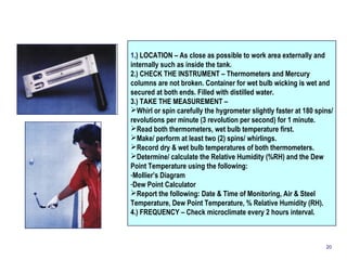
![Cathode (+) Cathode (+)
e- e-
Anode (-)
Acid Solution Droplet
Iron (Fe+++) Ions
Hydrogen Gas
2 H+ + 2 e- H2
[ Acid Solution + Iron Ion = Hydrogen Gas ]
2](https://image.slidesharecdn.com/001prz-corrosionprocessandcontrol-141111003052-conversion-gate01/85/Corrosion-Process-and-Control-3-320.jpg)
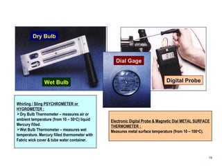
![1. UNIFORM (General)
CORROSION
Corrosion that develops at approximately the same
rate over the entire metal surfaces.
Steel
[Ignoble]
Corrosion on Steel 2. GALVANIC (Bimetallic)
Brass
[Noble]
CORROSION
Occurs when there is metallic contact between two dis-similar
metals in a corrosive environment.
Water more rich in Oxygen
becomes the Cathodic
region
Crevice becomes the
Oxygen depleted area, i.e.
Anodic region
Corroding Area
3. CREVICE CORROSION
Narrow crevices exposed to a liquid, typically water
containing solutions, may be open enough to allow the
liquid to penetrate, but still narrow that liquid becomes
stagnant & crevice corrosion occurs. The driving force
is the difference in Oxygen content inside & outside the
crevice.
3](https://image.slidesharecdn.com/001prz-corrosionprocessandcontrol-141111003052-conversion-gate01/85/Corrosion-Process-and-Control-4-320.jpg)
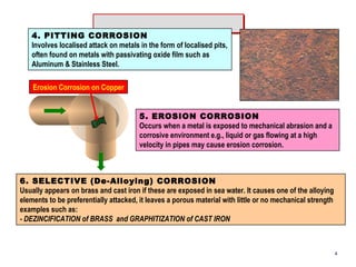
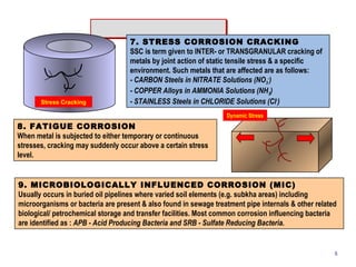
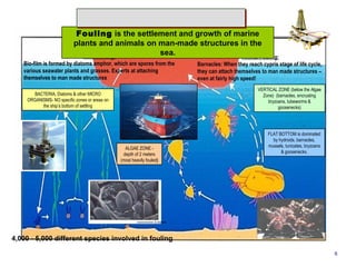
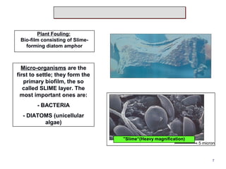
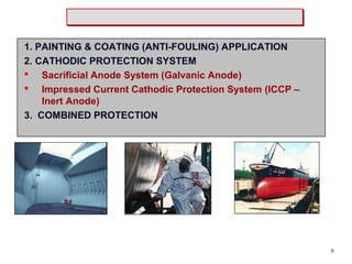
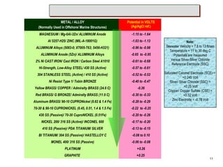
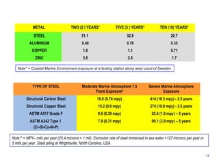
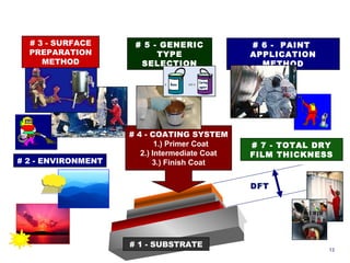
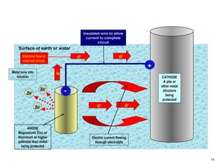
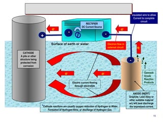

1. Corrosion is the degradation of materials like steel through chemical or electrochemical reaction with surrounding media like water and oxygen, forming rust (iron hydroxide). 2. Several types of corrosion are described, including uniform corrosion, galvanic corrosion, crevice corrosion, pitting corrosion, erosion corrosion, stress corrosion cracking, fatigue corrosion, and microbiologically influenced corrosion. 3. Methods to mitigate corrosion include protective coatings like paint and cathodic protection systems that use sacrificial anodes or impressed current to redirect corrosion to the anode from the protected structure. Surface preparation, coating selection, application, and achieving the proper dry film thickness are important.


