Download as PDF, PPTX
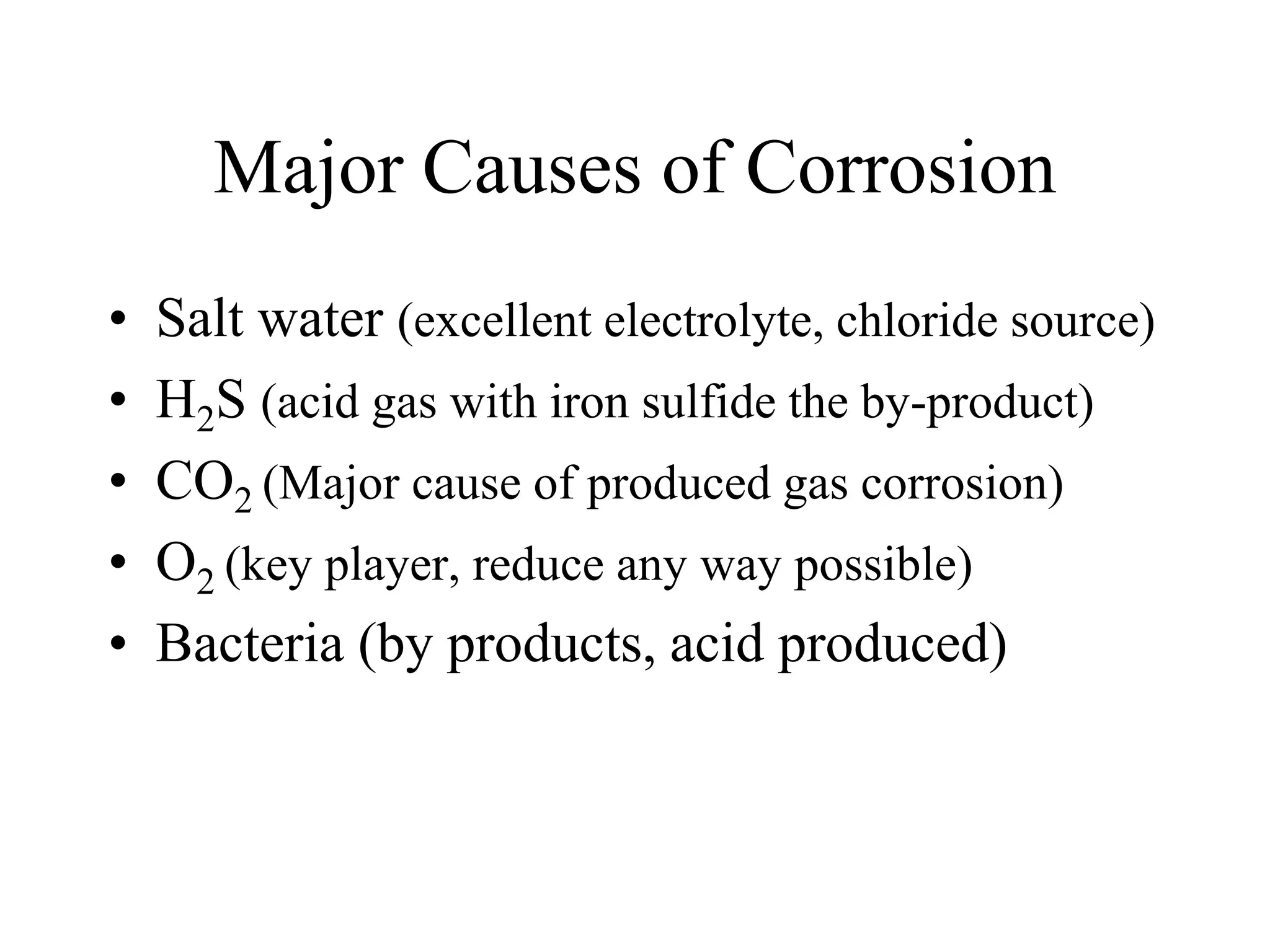

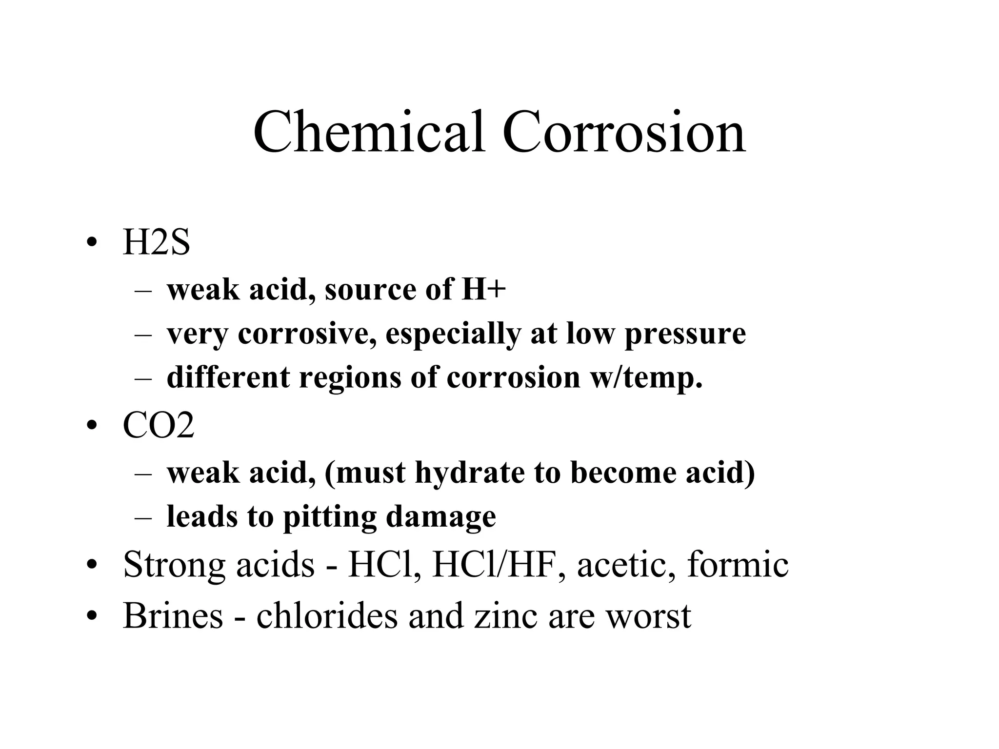
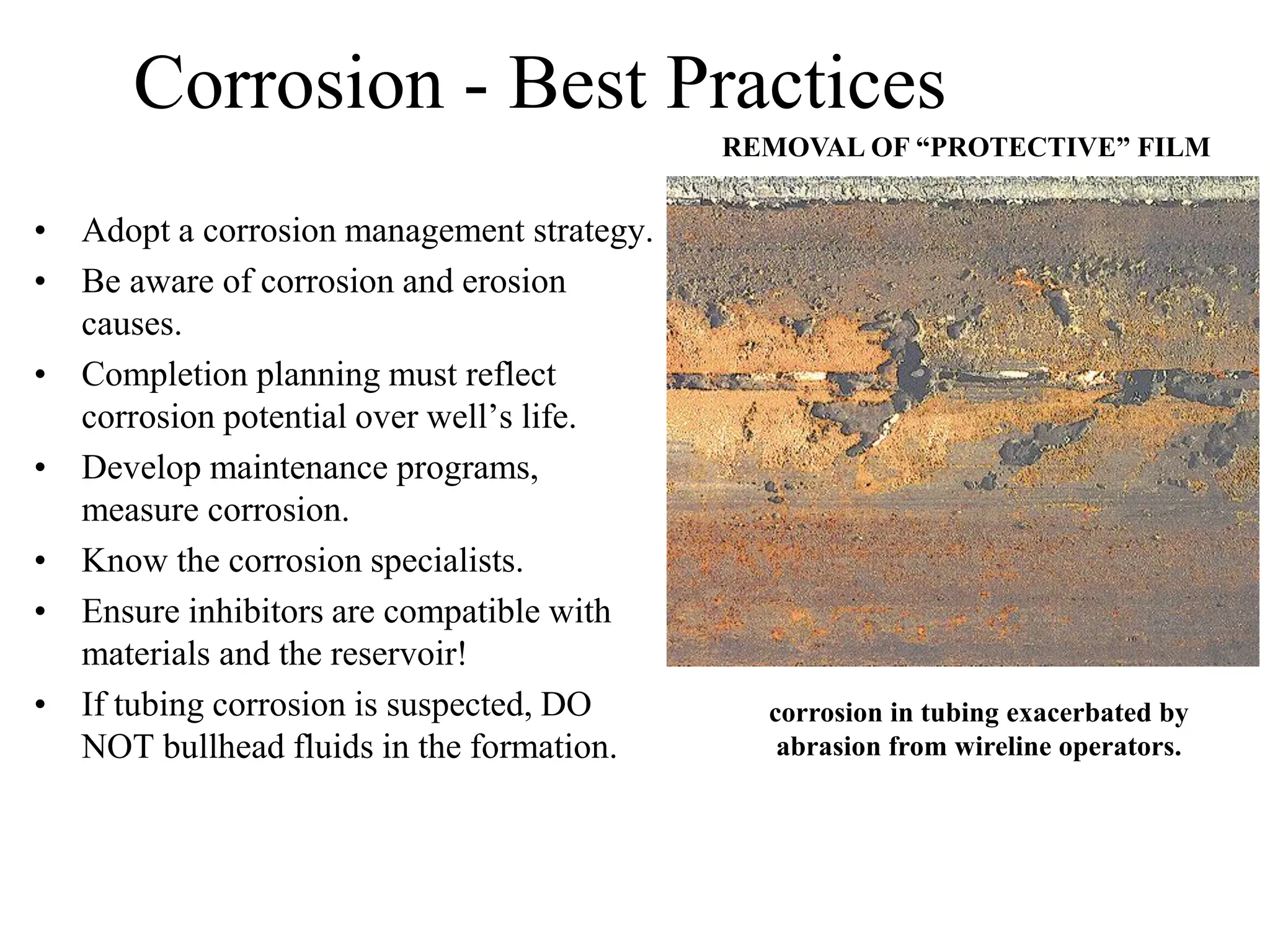


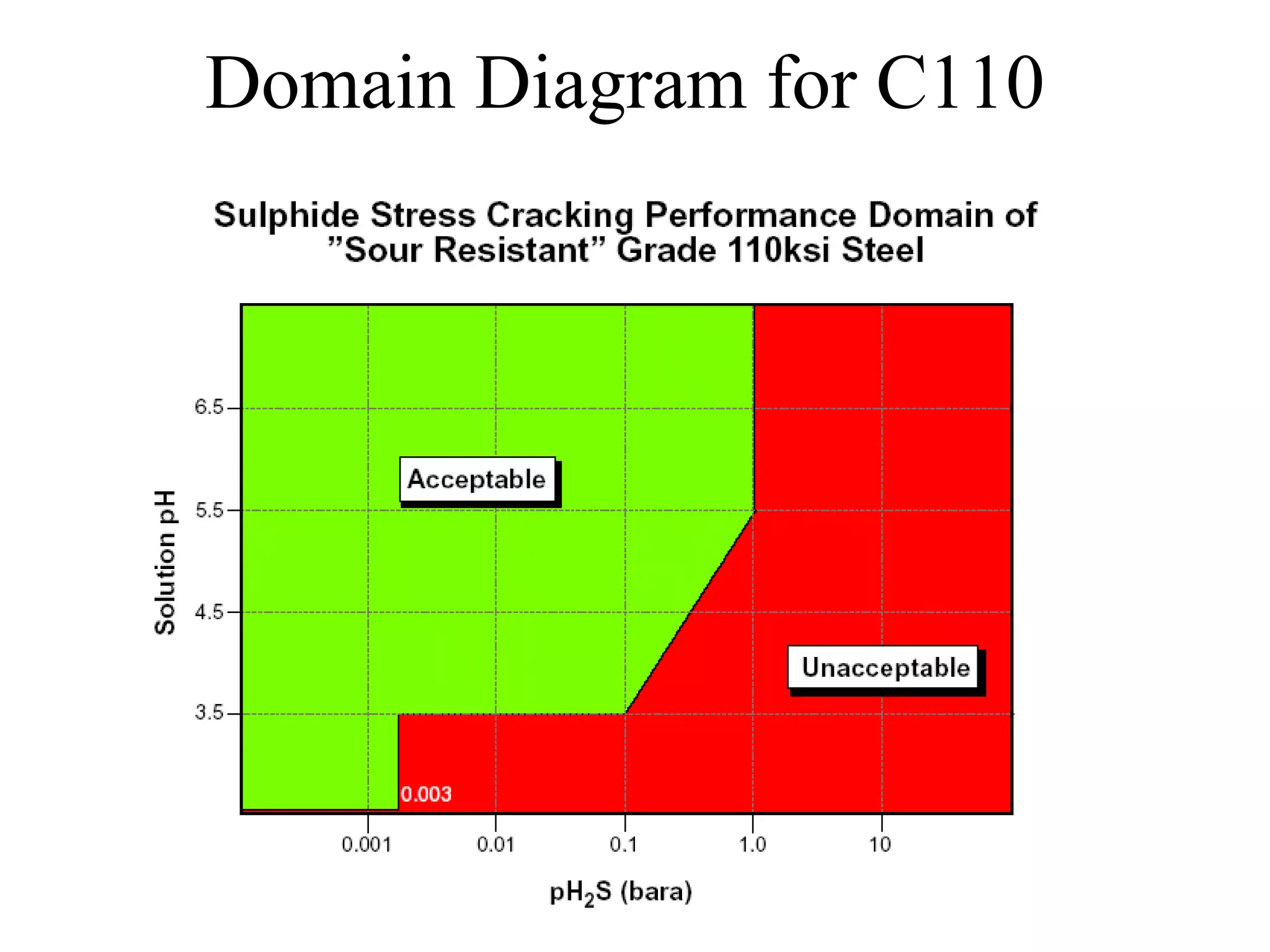
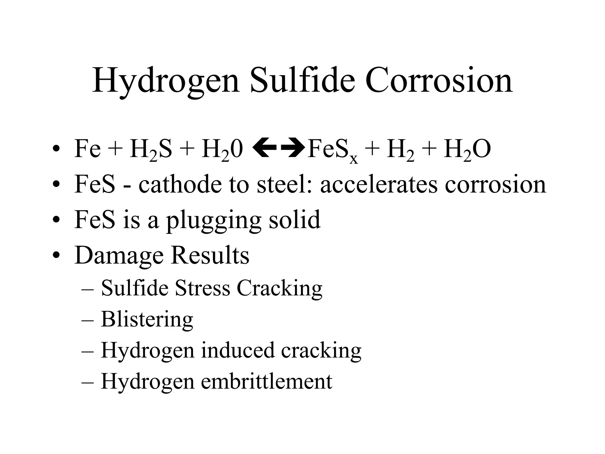


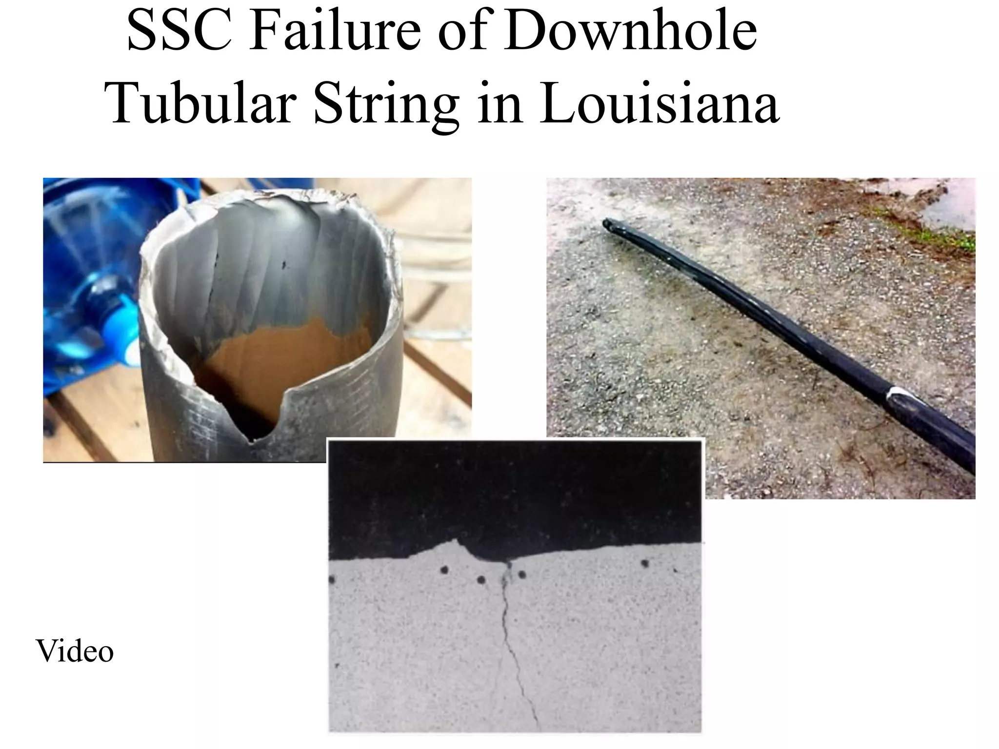


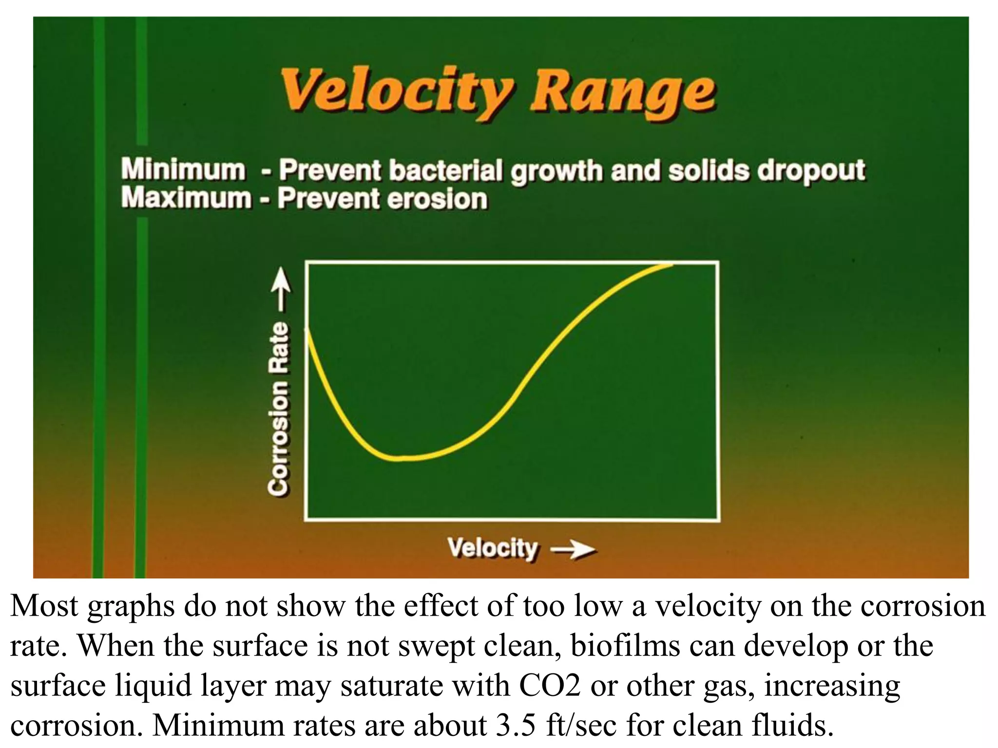


Corrosion in oil and gas operations can be caused by various factors including salt water, H2S, CO2, oxygen, bacteria, pH, temperature, and pressure. Different types of corrosion include galvanic, crevice, pitting, stress corrosion, and erosion corrosion. Proper materials selection and corrosion management strategies are needed to prevent corrosion from negatively impacting well integrity and operations over the life of a well.


