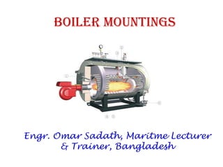
SlideShare a Scribd company logo
Boiler Mountings
Engr. Omar Sadath, Maritme Lecturer
& Trainer, Bangladesh
C/E Hanif Dewan 2
overview
Mountings are crucial
without which the
operation of boilers is
unsafe.
Proper maintenance and
care of the mountings is
important for the safety
of both the boiler and
the personnel and to
maintain optimum
operating condition of
the boiler.
Boiler Mountings:
The boiler mountings are the part of the boiler
and are required for proper functioning. In
accordance with the Indian Boiler regulations, of
the boiler mountings is essential fitting for
safe working of a boiler.
4
List of mountings
• Safety valves
• Water level indicators
• Water level controller
• Water level alarms & cut-out assembly
• Remote water level transmitter
• Main steam outlet valve
• Pressure gauge with cock & Pressure switches
• Feed water valves
• Burner assembly
• Air vent
• Water sampling valve
• Manholes, mud holes & peepholes
• Bottom blow down valve
• De-foaming (scum) valve
• Furnace drain valve
• Soot blowers
Water level Indicator
Water level indicator is
located in front of
boiler in such a position
that the level of water
can easily be seen by
attendant. Two water
level indicators are
used on all boilers.
C/E Hanif Dewan 6
Gauge glass
25mm
Lowest permissible water level
Lowest visible water level
51mm
Heating surface
Type of level Indicator and Switches
• Tubular gauge glass. Suitable for low pressure
boiler of design pressure below 17 bar.
• Reflex plate gauge glass. Suitable for boilers
design pressure below 34 bar.
• Double plate gauge glass. Suitable for boiler
design above 34 bar.
Double plate
Gauge Glass
8
Gauge glass
Reflex plate Gauge
Glass 9
Gauge glass
Regulation for Gauge Glass
• Every boiler is to be fitted with at least two
independent means of water level indicator. The
other means is to be either an additional glass
gauge or an approved equivalent device.
• Water tube boilers are to be fitted two system of
water level detection, which are to be
independent of any other mounting on the boiler.
Both the systems are to be operate audible and
visible alarm and automatic shut off.
Regulation for Gauge Glass
• Gauge glass to be so located that the lowest
visible water level in the glass is not lower
than 51 mm(2 in) above the lowest
permissible water level.
• The lowest permissible water level is just
above (usually 25 mm or 1 inch above) the top
row of tubes when cold.
How to repair a Gauge Glass
• Isolate the assembly by shutting of the steam
and water connection and by opening the drain.
• Take off the screws of the glass holder and
remove the pressure ledge.
• Remove the glass insert with gasket.
• Spare glass surface to be clean thoroughly.
• Install the black gasket ,the spare glass groove
facing inwards,the red gasket ,finally the thin
steel sheet.
How to repair a Gauge Glass
• Put the pressure ledges and tightened the screw
uniformly starting from the middle and proceding
crosswise up and downwards.
• Heat the new glass slowly by keeping the water
side valve shut, the steam side valve crack open
keeping the drain valve open.
• After 30 mins the screw should be retightened.
• The assembly can be put on load by shutting of
the drain valve and opening the steam and water
side valves completely open.
High low level alarm and burner cut-off
• All types of marine boiler must be fitted with high
low water level safeguards. All such of equipment
is to be capable of operating audible and visible
alarms and also of automatic shutting off the fuel
supply to the burners when the water level falls
to predetermined low level.
• Two types of level alarms are commonly found.
• Magnetic float switch type, Conductivity probes
type.
15
Level switch and Alarms
16
Low water level cutout failure
Pressure Gauge
A pressure gauge is fitted
in front of boiler in such a
position that the operator
can
conveniently read it. It
reads the pressure of
steam in the boiler and is
connected to steam
space by a siphon tube.
The most commonly, the
Bourdon pressure gauge is
used.
Safety Valve
Safety valves are located on the top of the boiler. They guard the
boiler against the excessive high pressure of steam inside the
drum. If the pressure of steam in the boiler drum exceeds the
working pressure then the safety valve allows blow-off the excess
quantity of steam to atmosphere. Thus the pressure of steam in
the drum falls. The escape of steam makes a audible noise to warn
the boiler attendant.
There are four types of safety valves:
1. Dead weight safety valve.
2. Spring loaded safety valve
3. Lever loaded safety valve
4. High steam and low water safety valve
According to design feature safety valve can be classified as
Ordinary lift, High lift, Improved high lift and full bore.
Dead weight safety valve Spring loaded safety valve
Lever loaded safety valve
20
Safety valves- Definitions
• Set Pressure: The boiler pressure at which the
safety valve begins to lift.
• Closing Pressure: The boiler pressure at which
the valve closes.
• Valve lift:The axial valve disc travel from closed to
the open position.
• Blow down: The difference between the opening
and the closing pressures. Too much blow down
causes wastage of steam, where as too little blow
down would give unstable condition.
21
Typical Safety Valves
22
Full lift safety valve
23
Full Lift = L= D/4
24
Safety Valve: Operation - Lifting
• In order to achieve full
opening from this
small overpressure,
the disc arrangement
has to be specially
designed to provide
rapid opening.
• This is usually done by
placing a shroud, skirt
or hood around the
disc.
• The volume contained
within this shroud is
known as the control
or huddling chamber.
25
Safety Valve: Operation - Lifting
• As lift begins and fluid enters the chamber, a larger area
of the shroud is exposed to the fluid pressure.
26
Safety Valve: Operation - Lifting
• Since the magnitude of the lifting force (F) is
proportional to the product of the pressure (P) and the
area exposed to the fluid (A); (F = P x A), the opening
force is increased.
27
Safety Valve: Operation - Lifting
• This incremental increase in opening force overcompensates
for the increase in spring force, causing rapid opening. At
the same time, the shroud reverses the direction of the
flow, which provides a reaction force, further enhancing the
lift.
28
Safety Valve Operation – Re-seatting
• The difference between the set pressure and this
reseating pressure is kno n as the blowdown
• It is usually specified as a percentage of the set
pressure.
• For compressible fluids, the blowdown is usually
less than 10%
• For liquids, it can be up to 20%.
REGULATION FOR SAFETY VALVE
• Number of safety valve.
• Size of safety valve.
• Superheater and economizer
30
Number of Safety Valves for Boiler
• Each boiler (including exhaust gas boiler) and steam
generator is to be fitted with at least one safety valve
and where the water-heating surface is more than
46.5 m2 (500 ft2), two or more safety valves are to be
provided.
• The valves are to be of equal size as far as practicable
and their aggregate relieving capacity is not to be
less than the evaporating capacity of the boiler
under maximum operating conditions.
31
Safety Valves – Size Restrictions
• In no case,
– is the inlet diameter of any safety valve for
propulsion boiler and superheaters used to
generate steam for main propulsion and other
machinery to be less than 38 mm (1.5 in.) nor
more than 102 mm (4 in.).
– For auxiliary boilers and exhaust gas
economizers, the inlet diameter of the safety
valve must not be less than 19 mm (3/4 in.) nor
more than 102 mm (4 in.).
32
Safety Valves – for Superheater & Economizer
• Superheater. Each superheater, regardless of
whether it can be isolated from the boiler or
not, is to be fitted with at least one safety
valve on the superheater outlet.
• Economizers. Each economizer, where fitted
with a bypass, is to be provided with a
sentinel relief valve, unless the bypass
arrangement will prevent a buildup of
pressure in the economizer when it is
bypassed.
33
Pressure Setting – Boiler Drums
• At least one safety valve on the boiler drum is to be set at or
below the maximum allowable working pressure.
• If more than one safety valve is installed, the highest setting
among the safety valves is not to exceed the maximum
allowable working pressure by more than 3%.
• The range of pressure settings of all the drum safety valves
is not to exceed 10% of the highest pressure to which any
safety valve is set.
• In no case is the relief pressure to be greater than the
design pressure of the steam piping or that of the
machinery connected to the boiler plus the pressure drop in
the steam piping.
34
Pressure Setting – Superheaters
• Where a superheater is fitted, the superheater safety valve is to
be set to relieve at a pressure no greater than the design
pressure of the steam piping or the design pressure of the
machinery connected to the superheater plus pressure drop in
the steam piping.
• In no case is the superheater safety valve to be set at a pressure
greater than the design pressure of the superheater.
• In connection with the superheater, the safety valves on the
boiler drum are to be set at a pressure not less than the
superheater-valve setting plus 0.34 bar (0.35 kgf/cm2, 5 psi), plus
approximately the normal-load pressure drop through the
superheater.
35
Safety Valve – Easing Gear
• Each boiler and superheater safety valve is to
be fitted with an efficient mechanical means
by which the valve disc may be positively
lifted from its seat.
• This mechanism is to be so arranged that the
valves may be safely operated from the boiler
room or machinery space platforms, either by
hand or by any approved power arrangement.
36
Safety Valve – Connection to Boiler & Superheater
• Safety valves are to be connected directly to the
boiler, except that they may be mounted on a
common fitting.
• However, they are not to be mounted on the
same fitting as that for the main or auxiliary
steam outlet.
• This does not apply to super heater safety
valves, which may be mounted on the fitting for
the super heater steam outlet.
37
Safety Valve – Escape Pipe
• The area of the escape pipe is to be at least
equal to the combined outlet area of all of the
safety valves discharging into it.
• The pipe is to be so routed as to prevent the
accumulation of condensate and is to be so
supported that the body of the safety valve is
not subjected to undue load or moment.
38
Safety Valve – Drain Pipe
• Safety valve chests are to be fitted with drain
pipes leading to the bilges or a suitable tank.
• No valve or cock is to be fitted in the drain
pipe.
39
Safety Valve – Pressure Accumulation Test
• Safety valves are to be set under steam and tested with
pressure accumulation tests in the presence of the Surveyor.
• The boiler pressure is not to rise more than 6% above the
maximum allowable working pressure when the steam stop
valve is closed under full firing condition for a duration of 15
minutes for firetube boilers and 7 minutes for watertube
boilers.
• During this test, no more feed water is to be supplied than
that necessary to maintain a safe working water level.
• The popping point of each safety valve is not to be more than
3% above its set pressure.
40
Safety Valve – Pressure Accumulation
Test (waiver)
• Where such accumulation tests are impractical because of
superheater design, an application to omit such tests may be
approved, provided the following are complied with:
– All safety valves are to be set in the presence of the Surveyor.
– Capacity tests have been completed in the presence of the Surveyor on each
valve
– type.
– The valve manufacturer supplies a certificate for each safety valve stating its
capacity at the maximum allowable working pressure and temperature of the
boiler.
– The boiler manufacturer supplies a certificate stating the maximum
evaporation of the boiler.
– Due consideration is given to back pressure in the safety valve steam escape
pipe.
41
Manhole door
Fusible Plug
It is very important safety device, which protects
the fire tube boiler against overheating. It is
located just above the furnace in the boiler. It
consists of gun metal plug fixed in a gun metal
body with fusible molten metal.
During the normal boiler operation, the fusible
plug is covered by water and its temperature
does not rise to its melting state. But when the
water level falls too low in the boiler, it
uncovers the fusible plug. The furnace gases heat
up the plug and fusible metal of plug melts,
the inner plug falls down The water and steam
then rush through the hole and extinguish the
fire before any major damage occurs to the boiler
due to overheating.
Blow-Off Cock
The function of blow-off cock is to
discharge mud and other sediments
deposited in the
bottom most part of the water space
in the boiler, while boiler is in
operation. It can also be
used to drain-off boiler water. Hence
it is mounted at the lowest part of
the boiler. When it is
open, water under the pressure
rushes out, thus carrying sediments
and mud.
Feed Check Valve
The feed check valve is
fitted to the boiler, slightly
below the working level in
the boiler. It
is used to supply high
pressure feed water to
boiler. It also prevents the
returning of feed
water from the boiler if
feed pump fails to work.
Steam Stop Valve
The steam stop valve
is located on the
highest part of the
steam space. It
regulates the steam
supply to use. The
steam stop valve can
be operated manually
or automatically.
46
Summary
• major mountings fitted on a boiler.
• significance of each of the mountings.
• Identify the various components of a gauge glass and safety
valve.
• Describe the constructional features of various basic types
of gauge glasses and safety valves.
• Explain the procedure for gauge glass blowing through.
• E plain the procedure for setting a safet al e s set
pressure and blowdown.
• Discuss the maintenance procedure for safety valve
assembly.
Thank You

More Related Content

What's hot

Subsurface safety valves
Subsurface safety valvesSubsurface safety valves
Subsurface safety valves
Akhilesh Maurya
 
Relief and safety valves for thermal power plants
Relief and safety valves for thermal power plantsRelief and safety valves for thermal power plants
Relief and safety valves for thermal power plants
SHIVAJI CHOUDHURY
 
Pressure safety valves
Pressure safety valvesPressure safety valves
Pressure safety valves
Amol Dudhate
 
Pressure Relief Devices_Presenation
Pressure Relief Devices_PresenationPressure Relief Devices_Presenation
Pressure Relief Devices_Presenation
sumit handa
 

What's hot (20)

Mechanical Seal Vs Gland Packing
Mechanical Seal  Vs Gland PackingMechanical Seal  Vs Gland Packing
Mechanical Seal Vs Gland Packing
 
1.seal mechanical seal
1.seal mechanical seal1.seal mechanical seal
1.seal mechanical seal
 
Sewage treatment plant on a ship explained
Sewage treatment plant on a ship explainedSewage treatment plant on a ship explained
Sewage treatment plant on a ship explained
 
complete guide to process valves
complete guide to process valves complete guide to process valves
complete guide to process valves
 
Pressure Relief valve sizing and design
Pressure Relief valve sizing and designPressure Relief valve sizing and design
Pressure Relief valve sizing and design
 
Subsurface safety valves
Subsurface safety valvesSubsurface safety valves
Subsurface safety valves
 
Electrical Isolation procedure onboard ship
Electrical Isolation procedure onboard shipElectrical Isolation procedure onboard ship
Electrical Isolation procedure onboard ship
 
Boiler condition survey
Boiler condition surveyBoiler condition survey
Boiler condition survey
 
Safety valve in process industry1
Safety valve in process industry1Safety valve in process industry1
Safety valve in process industry1
 
STEAM TURBINE BASIC
STEAM TURBINE BASIC STEAM TURBINE BASIC
STEAM TURBINE BASIC
 
Boiler Purging-Logic, Importance & Working
Boiler Purging-Logic, Importance & WorkingBoiler Purging-Logic, Importance & Working
Boiler Purging-Logic, Importance & Working
 
Priming of Centrifugal Pump
Priming of Centrifugal PumpPriming of Centrifugal Pump
Priming of Centrifugal Pump
 
Relief and safety valves for thermal power plants
Relief and safety valves for thermal power plantsRelief and safety valves for thermal power plants
Relief and safety valves for thermal power plants
 
Pipeline Strainers - A Tutorial
Pipeline Strainers - A TutorialPipeline Strainers - A Tutorial
Pipeline Strainers - A Tutorial
 
Safety valves
Safety valvesSafety valves
Safety valves
 
Heat exchanger types and hydro testing
Heat exchanger types and hydro testingHeat exchanger types and hydro testing
Heat exchanger types and hydro testing
 
SPII Compact Wellhead - Worldwide Oilfield Machine Inc.
SPII Compact Wellhead - Worldwide Oilfield Machine Inc.SPII Compact Wellhead - Worldwide Oilfield Machine Inc.
SPII Compact Wellhead - Worldwide Oilfield Machine Inc.
 
Pressure safety valves
Pressure safety valvesPressure safety valves
Pressure safety valves
 
Boiler ppt
Boiler pptBoiler ppt
Boiler ppt
 
Pressure Relief Devices_Presenation
Pressure Relief Devices_PresenationPressure Relief Devices_Presenation
Pressure Relief Devices_Presenation
 

Similar to Boiler Mountings

Pre commissioning steam turbines load trial
Pre commissioning steam turbines load trialPre commissioning steam turbines load trial
Pre commissioning steam turbines load trial
Nagesh H
 

Similar to Boiler Mountings (20)

Safety Valves.ppt
Safety Valves.pptSafety Valves.ppt
Safety Valves.ppt
 
Leak Tests.pptx
Leak Tests.pptxLeak Tests.pptx
Leak Tests.pptx
 
Final Presentation Mehedei ID-13207016.pptx
Final Presentation Mehedei ID-13207016.pptxFinal Presentation Mehedei ID-13207016.pptx
Final Presentation Mehedei ID-13207016.pptx
 
The basic anaesthesia machine
The basic anaesthesia machineThe basic anaesthesia machine
The basic anaesthesia machine
 
170990119015 17 ohp-mechanical 7th sem
170990119015 17 ohp-mechanical 7th sem170990119015 17 ohp-mechanical 7th sem
170990119015 17 ohp-mechanical 7th sem
 
Turbine vacuum system.ppt
Turbine vacuum system.pptTurbine vacuum system.ppt
Turbine vacuum system.ppt
 
Boiler safety
Boiler safetyBoiler safety
Boiler safety
 
Ten things about txv operation troubleshooting - Danfoss Cooling
Ten things about txv operation troubleshooting - Danfoss CoolingTen things about txv operation troubleshooting - Danfoss Cooling
Ten things about txv operation troubleshooting - Danfoss Cooling
 
Api682
Api682Api682
Api682
 
Lessons learned solving pilot valve instability issues on LNG storage tanks
Lessons learned solving pilot valve instability issues on LNG storage tanksLessons learned solving pilot valve instability issues on LNG storage tanks
Lessons learned solving pilot valve instability issues on LNG storage tanks
 
PSV Sizing.pdf
PSV Sizing.pdfPSV Sizing.pdf
PSV Sizing.pdf
 
Piping system
Piping systemPiping system
Piping system
 
Intermediate & low pressure system
Intermediate & low pressure systemIntermediate & low pressure system
Intermediate & low pressure system
 
API682 Mechanical Seal Plan and Requirements of Mechanical Seals
API682 Mechanical Seal Plan and Requirements of Mechanical SealsAPI682 Mechanical Seal Plan and Requirements of Mechanical Seals
API682 Mechanical Seal Plan and Requirements of Mechanical Seals
 
API 682 Seal piping plans.pdf
API 682 Seal piping plans.pdfAPI 682 Seal piping plans.pdf
API 682 Seal piping plans.pdf
 
INTERMEDIATE PRESSURE SYSTEM.pptx
INTERMEDIATE PRESSURE SYSTEM.pptxINTERMEDIATE PRESSURE SYSTEM.pptx
INTERMEDIATE PRESSURE SYSTEM.pptx
 
Condensate Return Solutions.ppt
Condensate Return Solutions.pptCondensate Return Solutions.ppt
Condensate Return Solutions.ppt
 
Pre commissioning steam turbines load trial
Pre commissioning steam turbines load trialPre commissioning steam turbines load trial
Pre commissioning steam turbines load trial
 
Central heating level 3
Central heating level 3Central heating level 3
Central heating level 3
 
Presentation on Expansion Devices
Presentation on Expansion DevicesPresentation on Expansion Devices
Presentation on Expansion Devices
 

Recently uploaded

Accounting and finance exit exam 2016 E.C.pdf
Accounting and finance exit exam 2016 E.C.pdfAccounting and finance exit exam 2016 E.C.pdf
Accounting and finance exit exam 2016 E.C.pdf
YibeltalNibretu
 
Industrial Training Report- AKTU Industrial Training Report
Industrial Training Report- AKTU Industrial Training ReportIndustrial Training Report- AKTU Industrial Training Report
Industrial Training Report- AKTU Industrial Training Report
Avinash Rai
 
Adversarial Attention Modeling for Multi-dimensional Emotion Regression.pdf
Adversarial Attention Modeling for Multi-dimensional Emotion Regression.pdfAdversarial Attention Modeling for Multi-dimensional Emotion Regression.pdf
Adversarial Attention Modeling for Multi-dimensional Emotion Regression.pdf
Po-Chuan Chen
 
Additional Benefits for Employee Website.pdf
Additional Benefits for Employee Website.pdfAdditional Benefits for Employee Website.pdf
Additional Benefits for Employee Website.pdf
joachimlavalley1
 

Recently uploaded (20)

Accounting and finance exit exam 2016 E.C.pdf
Accounting and finance exit exam 2016 E.C.pdfAccounting and finance exit exam 2016 E.C.pdf
Accounting and finance exit exam 2016 E.C.pdf
 
Gyanartha SciBizTech Quiz slideshare.pptx
Gyanartha SciBizTech Quiz slideshare.pptxGyanartha SciBizTech Quiz slideshare.pptx
Gyanartha SciBizTech Quiz slideshare.pptx
 
Basic Civil Engineering Notes of Chapter-6, Topic- Ecosystem, Biodiversity G...
Basic Civil Engineering Notes of Chapter-6,  Topic- Ecosystem, Biodiversity G...Basic Civil Engineering Notes of Chapter-6,  Topic- Ecosystem, Biodiversity G...
Basic Civil Engineering Notes of Chapter-6, Topic- Ecosystem, Biodiversity G...
 
Synthetic Fiber Construction in lab .pptx
Synthetic Fiber Construction in lab .pptxSynthetic Fiber Construction in lab .pptx
Synthetic Fiber Construction in lab .pptx
 
Industrial Training Report- AKTU Industrial Training Report
Industrial Training Report- AKTU Industrial Training ReportIndustrial Training Report- AKTU Industrial Training Report
Industrial Training Report- AKTU Industrial Training Report
 
GIÁO ÁN DẠY THÊM (KẾ HOẠCH BÀI BUỔI 2) - TIẾNG ANH 8 GLOBAL SUCCESS (2 CỘT) N...
GIÁO ÁN DẠY THÊM (KẾ HOẠCH BÀI BUỔI 2) - TIẾNG ANH 8 GLOBAL SUCCESS (2 CỘT) N...GIÁO ÁN DẠY THÊM (KẾ HOẠCH BÀI BUỔI 2) - TIẾNG ANH 8 GLOBAL SUCCESS (2 CỘT) N...
GIÁO ÁN DẠY THÊM (KẾ HOẠCH BÀI BUỔI 2) - TIẾNG ANH 8 GLOBAL SUCCESS (2 CỘT) N...
 
Adversarial Attention Modeling for Multi-dimensional Emotion Regression.pdf
Adversarial Attention Modeling for Multi-dimensional Emotion Regression.pdfAdversarial Attention Modeling for Multi-dimensional Emotion Regression.pdf
Adversarial Attention Modeling for Multi-dimensional Emotion Regression.pdf
 
Instructions for Submissions thorugh G- Classroom.pptx
Instructions for Submissions thorugh G- Classroom.pptxInstructions for Submissions thorugh G- Classroom.pptx
Instructions for Submissions thorugh G- Classroom.pptx
 
How to Create Map Views in the Odoo 17 ERP
How to Create Map Views in the Odoo 17 ERPHow to Create Map Views in the Odoo 17 ERP
How to Create Map Views in the Odoo 17 ERP
 
Danh sách HSG Bộ môn cấp trường - Cấp THPT.pdf
Danh sách HSG Bộ môn cấp trường - Cấp THPT.pdfDanh sách HSG Bộ môn cấp trường - Cấp THPT.pdf
Danh sách HSG Bộ môn cấp trường - Cấp THPT.pdf
 
Benefits and Challenges of Using Open Educational Resources
Benefits and Challenges of Using Open Educational ResourcesBenefits and Challenges of Using Open Educational Resources
Benefits and Challenges of Using Open Educational Resources
 
MARUTI SUZUKI- A Successful Joint Venture in India.pptx
MARUTI SUZUKI- A Successful Joint Venture in India.pptxMARUTI SUZUKI- A Successful Joint Venture in India.pptx
MARUTI SUZUKI- A Successful Joint Venture in India.pptx
 
Home assignment II on Spectroscopy 2024 Answers.pdf
Home assignment II on Spectroscopy 2024 Answers.pdfHome assignment II on Spectroscopy 2024 Answers.pdf
Home assignment II on Spectroscopy 2024 Answers.pdf
 
Operations Management - Book1.p - Dr. Abdulfatah A. Salem
Operations Management - Book1.p  - Dr. Abdulfatah A. SalemOperations Management - Book1.p  - Dr. Abdulfatah A. Salem
Operations Management - Book1.p - Dr. Abdulfatah A. Salem
 
The Art Pastor's Guide to Sabbath | Steve Thomason
The Art Pastor's Guide to Sabbath | Steve ThomasonThe Art Pastor's Guide to Sabbath | Steve Thomason
The Art Pastor's Guide to Sabbath | Steve Thomason
 
PART A. Introduction to Costumer Service
PART A. Introduction to Costumer ServicePART A. Introduction to Costumer Service
PART A. Introduction to Costumer Service
 
Sha'Carri Richardson Presentation 202345
Sha'Carri Richardson Presentation 202345Sha'Carri Richardson Presentation 202345
Sha'Carri Richardson Presentation 202345
 
Additional Benefits for Employee Website.pdf
Additional Benefits for Employee Website.pdfAdditional Benefits for Employee Website.pdf
Additional Benefits for Employee Website.pdf
 
Advances in production technology of Grapes.pdf
Advances in production technology of Grapes.pdfAdvances in production technology of Grapes.pdf
Advances in production technology of Grapes.pdf
 
[GDSC YCCE] Build with AI Online Presentation
[GDSC YCCE] Build with AI Online Presentation[GDSC YCCE] Build with AI Online Presentation
[GDSC YCCE] Build with AI Online Presentation
 

Boiler Mountings

  • 1. Boiler Mountings Engr. Omar Sadath, Maritme Lecturer & Trainer, Bangladesh
  • 2. C/E Hanif Dewan 2 overview Mountings are crucial without which the operation of boilers is unsafe. Proper maintenance and care of the mountings is important for the safety of both the boiler and the personnel and to maintain optimum operating condition of the boiler.
  • 3. Boiler Mountings: The boiler mountings are the part of the boiler and are required for proper functioning. In accordance with the Indian Boiler regulations, of the boiler mountings is essential fitting for safe working of a boiler.
  • 4. 4 List of mountings • Safety valves • Water level indicators • Water level controller • Water level alarms & cut-out assembly • Remote water level transmitter • Main steam outlet valve • Pressure gauge with cock & Pressure switches • Feed water valves • Burner assembly • Air vent • Water sampling valve • Manholes, mud holes & peepholes • Bottom blow down valve • De-foaming (scum) valve • Furnace drain valve • Soot blowers
  • 5. Water level Indicator Water level indicator is located in front of boiler in such a position that the level of water can easily be seen by attendant. Two water level indicators are used on all boilers.
  • 6. C/E Hanif Dewan 6 Gauge glass 25mm Lowest permissible water level Lowest visible water level 51mm Heating surface
  • 7. Type of level Indicator and Switches • Tubular gauge glass. Suitable for low pressure boiler of design pressure below 17 bar. • Reflex plate gauge glass. Suitable for boilers design pressure below 34 bar. • Double plate gauge glass. Suitable for boiler design above 34 bar.
  • 9. Reflex plate Gauge Glass 9 Gauge glass
  • 10. Regulation for Gauge Glass • Every boiler is to be fitted with at least two independent means of water level indicator. The other means is to be either an additional glass gauge or an approved equivalent device. • Water tube boilers are to be fitted two system of water level detection, which are to be independent of any other mounting on the boiler. Both the systems are to be operate audible and visible alarm and automatic shut off.
  • 11. Regulation for Gauge Glass • Gauge glass to be so located that the lowest visible water level in the glass is not lower than 51 mm(2 in) above the lowest permissible water level. • The lowest permissible water level is just above (usually 25 mm or 1 inch above) the top row of tubes when cold.
  • 12. How to repair a Gauge Glass • Isolate the assembly by shutting of the steam and water connection and by opening the drain. • Take off the screws of the glass holder and remove the pressure ledge. • Remove the glass insert with gasket. • Spare glass surface to be clean thoroughly. • Install the black gasket ,the spare glass groove facing inwards,the red gasket ,finally the thin steel sheet.
  • 13. How to repair a Gauge Glass • Put the pressure ledges and tightened the screw uniformly starting from the middle and proceding crosswise up and downwards. • Heat the new glass slowly by keeping the water side valve shut, the steam side valve crack open keeping the drain valve open. • After 30 mins the screw should be retightened. • The assembly can be put on load by shutting of the drain valve and opening the steam and water side valves completely open.
  • 14. High low level alarm and burner cut-off • All types of marine boiler must be fitted with high low water level safeguards. All such of equipment is to be capable of operating audible and visible alarms and also of automatic shutting off the fuel supply to the burners when the water level falls to predetermined low level. • Two types of level alarms are commonly found. • Magnetic float switch type, Conductivity probes type.
  • 16. 16 Low water level cutout failure
  • 17. Pressure Gauge A pressure gauge is fitted in front of boiler in such a position that the operator can conveniently read it. It reads the pressure of steam in the boiler and is connected to steam space by a siphon tube. The most commonly, the Bourdon pressure gauge is used.
  • 18. Safety Valve Safety valves are located on the top of the boiler. They guard the boiler against the excessive high pressure of steam inside the drum. If the pressure of steam in the boiler drum exceeds the working pressure then the safety valve allows blow-off the excess quantity of steam to atmosphere. Thus the pressure of steam in the drum falls. The escape of steam makes a audible noise to warn the boiler attendant. There are four types of safety valves: 1. Dead weight safety valve. 2. Spring loaded safety valve 3. Lever loaded safety valve 4. High steam and low water safety valve According to design feature safety valve can be classified as Ordinary lift, High lift, Improved high lift and full bore.
  • 19. Dead weight safety valve Spring loaded safety valve Lever loaded safety valve
  • 20. 20 Safety valves- Definitions • Set Pressure: The boiler pressure at which the safety valve begins to lift. • Closing Pressure: The boiler pressure at which the valve closes. • Valve lift:The axial valve disc travel from closed to the open position. • Blow down: The difference between the opening and the closing pressures. Too much blow down causes wastage of steam, where as too little blow down would give unstable condition.
  • 23. 23 Full Lift = L= D/4
  • 24. 24 Safety Valve: Operation - Lifting • In order to achieve full opening from this small overpressure, the disc arrangement has to be specially designed to provide rapid opening. • This is usually done by placing a shroud, skirt or hood around the disc. • The volume contained within this shroud is known as the control or huddling chamber.
  • 25. 25 Safety Valve: Operation - Lifting • As lift begins and fluid enters the chamber, a larger area of the shroud is exposed to the fluid pressure.
  • 26. 26 Safety Valve: Operation - Lifting • Since the magnitude of the lifting force (F) is proportional to the product of the pressure (P) and the area exposed to the fluid (A); (F = P x A), the opening force is increased.
  • 27. 27 Safety Valve: Operation - Lifting • This incremental increase in opening force overcompensates for the increase in spring force, causing rapid opening. At the same time, the shroud reverses the direction of the flow, which provides a reaction force, further enhancing the lift.
  • 28. 28 Safety Valve Operation – Re-seatting • The difference between the set pressure and this reseating pressure is kno n as the blowdown • It is usually specified as a percentage of the set pressure. • For compressible fluids, the blowdown is usually less than 10% • For liquids, it can be up to 20%.
  • 29. REGULATION FOR SAFETY VALVE • Number of safety valve. • Size of safety valve. • Superheater and economizer
  • 30. 30 Number of Safety Valves for Boiler • Each boiler (including exhaust gas boiler) and steam generator is to be fitted with at least one safety valve and where the water-heating surface is more than 46.5 m2 (500 ft2), two or more safety valves are to be provided. • The valves are to be of equal size as far as practicable and their aggregate relieving capacity is not to be less than the evaporating capacity of the boiler under maximum operating conditions.
  • 31. 31 Safety Valves – Size Restrictions • In no case, – is the inlet diameter of any safety valve for propulsion boiler and superheaters used to generate steam for main propulsion and other machinery to be less than 38 mm (1.5 in.) nor more than 102 mm (4 in.). – For auxiliary boilers and exhaust gas economizers, the inlet diameter of the safety valve must not be less than 19 mm (3/4 in.) nor more than 102 mm (4 in.).
  • 32. 32 Safety Valves – for Superheater & Economizer • Superheater. Each superheater, regardless of whether it can be isolated from the boiler or not, is to be fitted with at least one safety valve on the superheater outlet. • Economizers. Each economizer, where fitted with a bypass, is to be provided with a sentinel relief valve, unless the bypass arrangement will prevent a buildup of pressure in the economizer when it is bypassed.
  • 33. 33 Pressure Setting – Boiler Drums • At least one safety valve on the boiler drum is to be set at or below the maximum allowable working pressure. • If more than one safety valve is installed, the highest setting among the safety valves is not to exceed the maximum allowable working pressure by more than 3%. • The range of pressure settings of all the drum safety valves is not to exceed 10% of the highest pressure to which any safety valve is set. • In no case is the relief pressure to be greater than the design pressure of the steam piping or that of the machinery connected to the boiler plus the pressure drop in the steam piping.
  • 34. 34 Pressure Setting – Superheaters • Where a superheater is fitted, the superheater safety valve is to be set to relieve at a pressure no greater than the design pressure of the steam piping or the design pressure of the machinery connected to the superheater plus pressure drop in the steam piping. • In no case is the superheater safety valve to be set at a pressure greater than the design pressure of the superheater. • In connection with the superheater, the safety valves on the boiler drum are to be set at a pressure not less than the superheater-valve setting plus 0.34 bar (0.35 kgf/cm2, 5 psi), plus approximately the normal-load pressure drop through the superheater.
  • 35. 35 Safety Valve – Easing Gear • Each boiler and superheater safety valve is to be fitted with an efficient mechanical means by which the valve disc may be positively lifted from its seat. • This mechanism is to be so arranged that the valves may be safely operated from the boiler room or machinery space platforms, either by hand or by any approved power arrangement.
  • 36. 36 Safety Valve – Connection to Boiler & Superheater • Safety valves are to be connected directly to the boiler, except that they may be mounted on a common fitting. • However, they are not to be mounted on the same fitting as that for the main or auxiliary steam outlet. • This does not apply to super heater safety valves, which may be mounted on the fitting for the super heater steam outlet.
  • 37. 37 Safety Valve – Escape Pipe • The area of the escape pipe is to be at least equal to the combined outlet area of all of the safety valves discharging into it. • The pipe is to be so routed as to prevent the accumulation of condensate and is to be so supported that the body of the safety valve is not subjected to undue load or moment.
  • 38. 38 Safety Valve – Drain Pipe • Safety valve chests are to be fitted with drain pipes leading to the bilges or a suitable tank. • No valve or cock is to be fitted in the drain pipe.
  • 39. 39 Safety Valve – Pressure Accumulation Test • Safety valves are to be set under steam and tested with pressure accumulation tests in the presence of the Surveyor. • The boiler pressure is not to rise more than 6% above the maximum allowable working pressure when the steam stop valve is closed under full firing condition for a duration of 15 minutes for firetube boilers and 7 minutes for watertube boilers. • During this test, no more feed water is to be supplied than that necessary to maintain a safe working water level. • The popping point of each safety valve is not to be more than 3% above its set pressure.
  • 40. 40 Safety Valve – Pressure Accumulation Test (waiver) • Where such accumulation tests are impractical because of superheater design, an application to omit such tests may be approved, provided the following are complied with: – All safety valves are to be set in the presence of the Surveyor. – Capacity tests have been completed in the presence of the Surveyor on each valve – type. – The valve manufacturer supplies a certificate for each safety valve stating its capacity at the maximum allowable working pressure and temperature of the boiler. – The boiler manufacturer supplies a certificate stating the maximum evaporation of the boiler. – Due consideration is given to back pressure in the safety valve steam escape pipe.
  • 42. Fusible Plug It is very important safety device, which protects the fire tube boiler against overheating. It is located just above the furnace in the boiler. It consists of gun metal plug fixed in a gun metal body with fusible molten metal. During the normal boiler operation, the fusible plug is covered by water and its temperature does not rise to its melting state. But when the water level falls too low in the boiler, it uncovers the fusible plug. The furnace gases heat up the plug and fusible metal of plug melts, the inner plug falls down The water and steam then rush through the hole and extinguish the fire before any major damage occurs to the boiler due to overheating.
  • 43. Blow-Off Cock The function of blow-off cock is to discharge mud and other sediments deposited in the bottom most part of the water space in the boiler, while boiler is in operation. It can also be used to drain-off boiler water. Hence it is mounted at the lowest part of the boiler. When it is open, water under the pressure rushes out, thus carrying sediments and mud.
  • 44. Feed Check Valve The feed check valve is fitted to the boiler, slightly below the working level in the boiler. It is used to supply high pressure feed water to boiler. It also prevents the returning of feed water from the boiler if feed pump fails to work.
  • 45. Steam Stop Valve The steam stop valve is located on the highest part of the steam space. It regulates the steam supply to use. The steam stop valve can be operated manually or automatically.
  • 46. 46 Summary • major mountings fitted on a boiler. • significance of each of the mountings. • Identify the various components of a gauge glass and safety valve. • Describe the constructional features of various basic types of gauge glasses and safety valves. • Explain the procedure for gauge glass blowing through. • E plain the procedure for setting a safet al e s set pressure and blowdown. • Discuss the maintenance procedure for safety valve assembly.