Downloaded 123 times


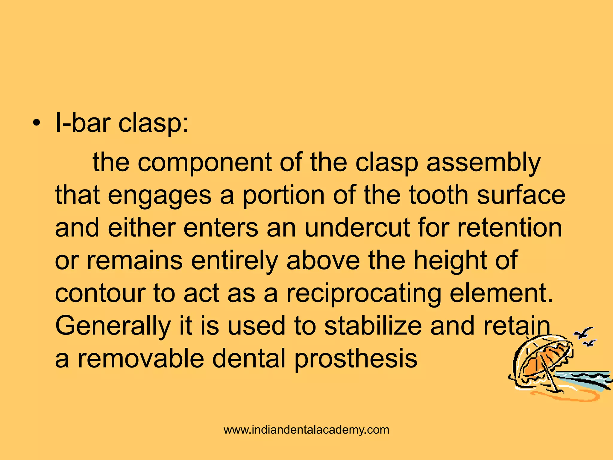


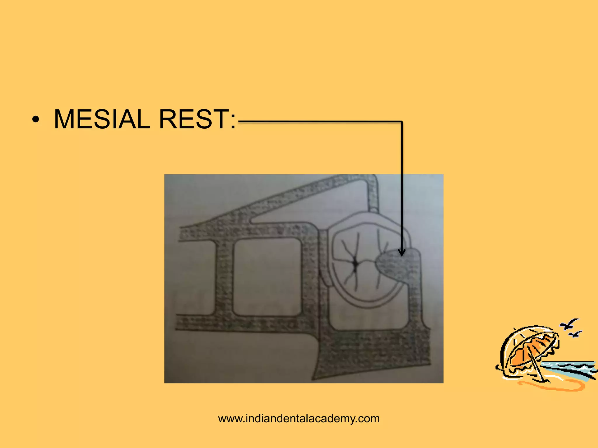
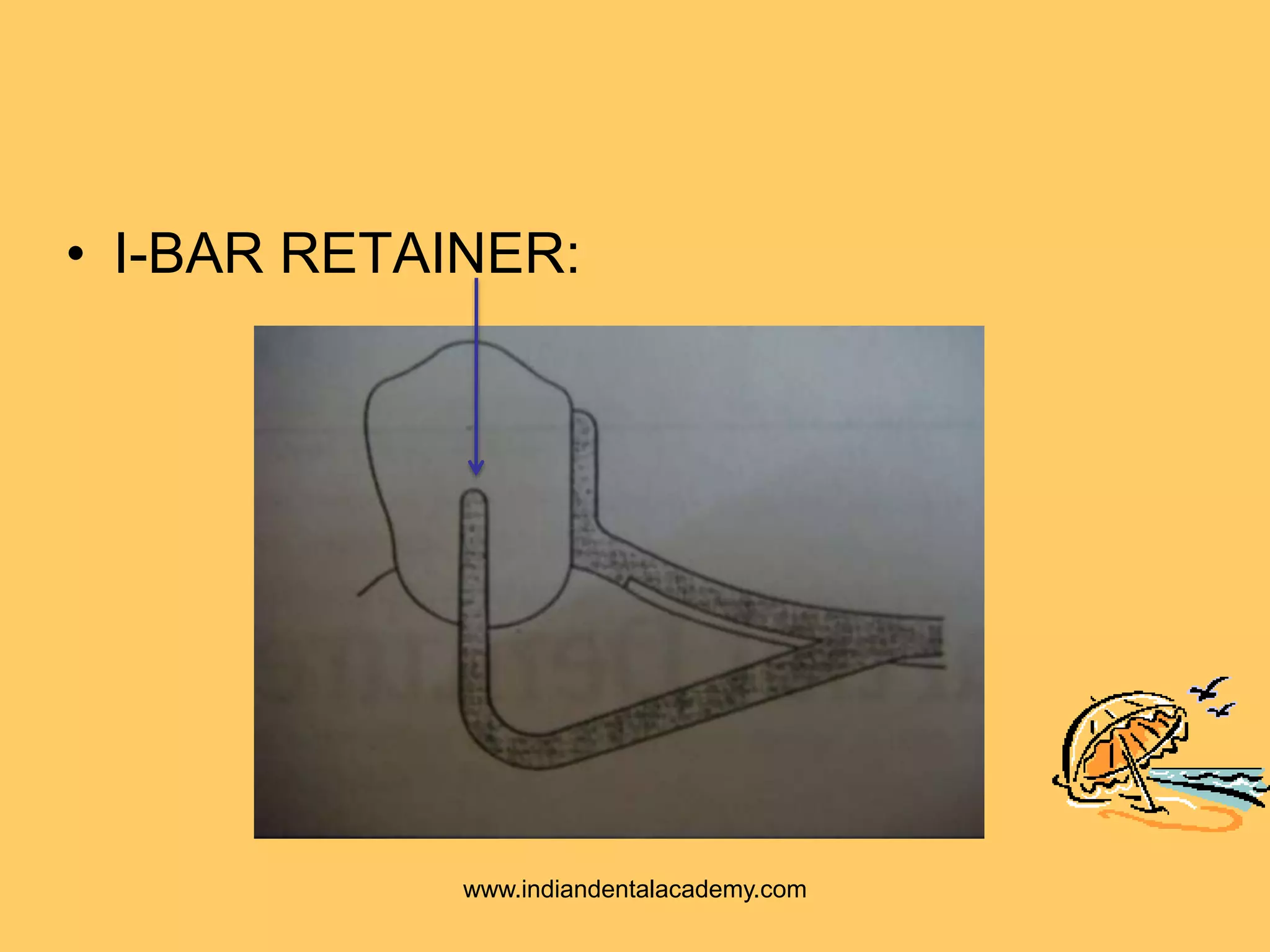


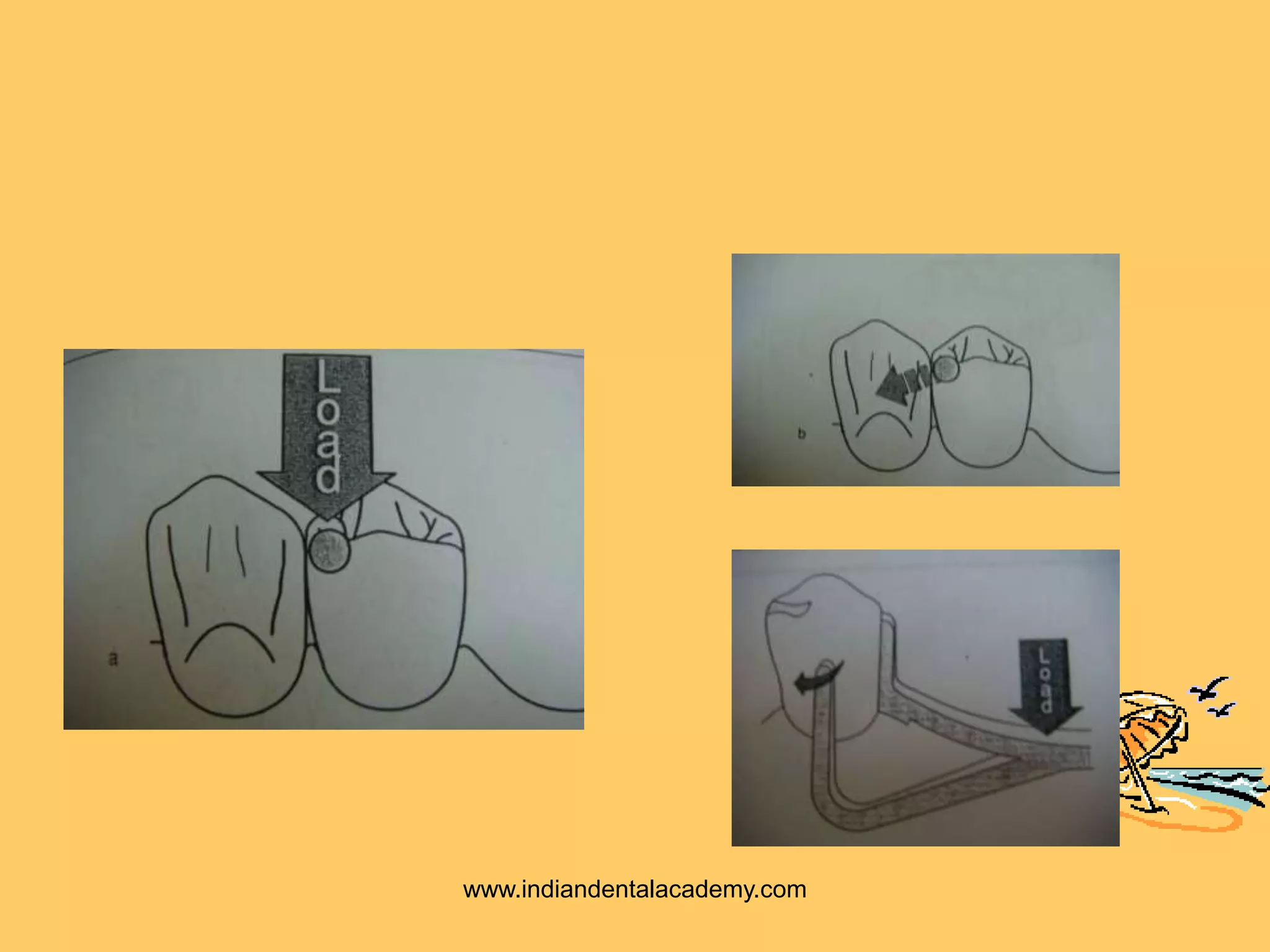


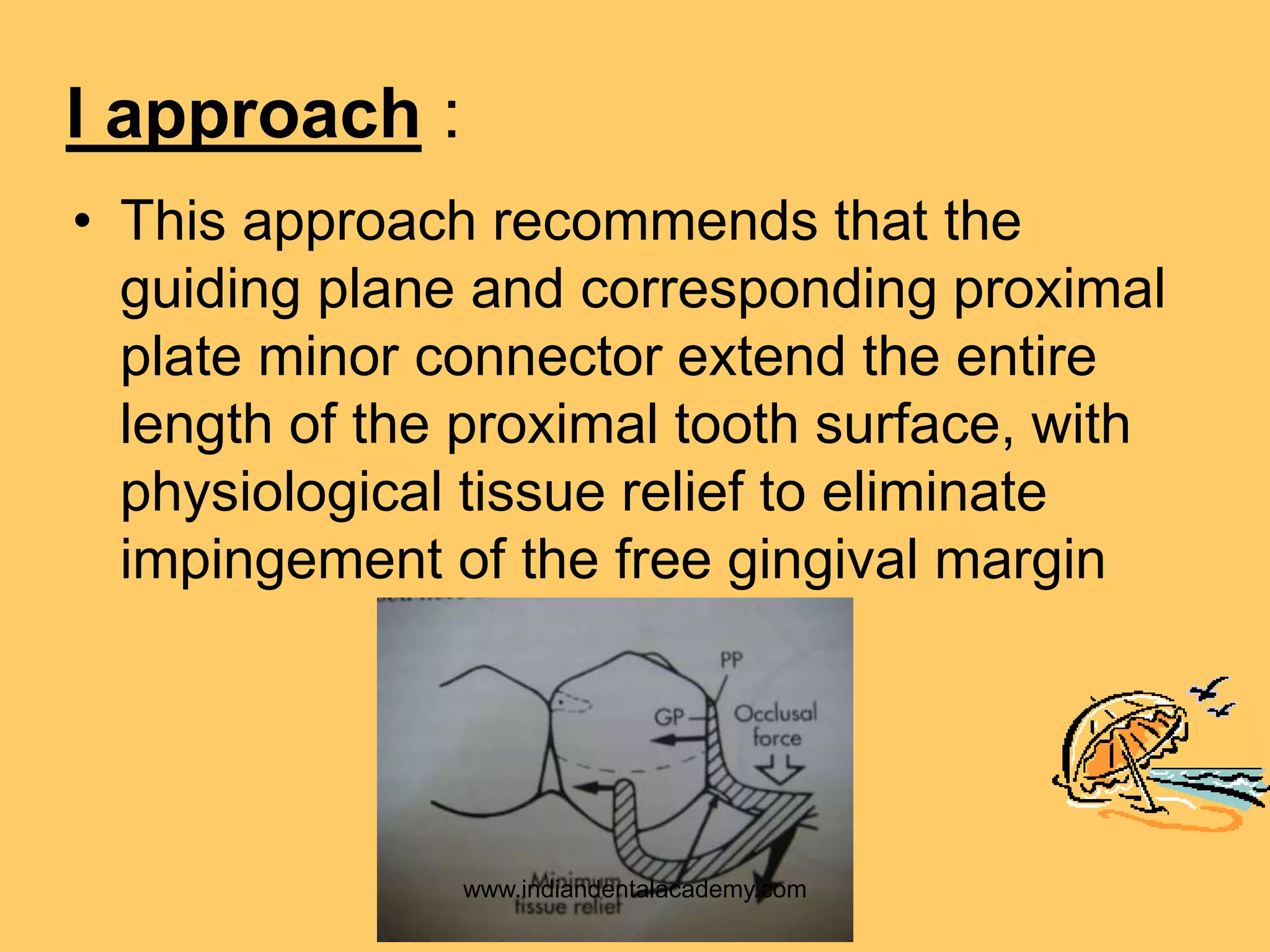
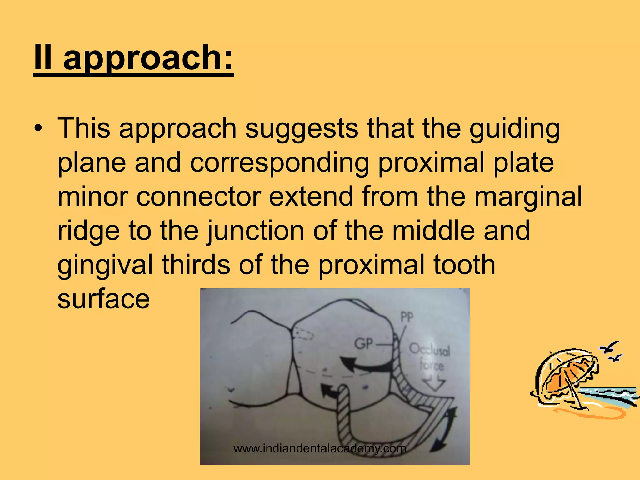

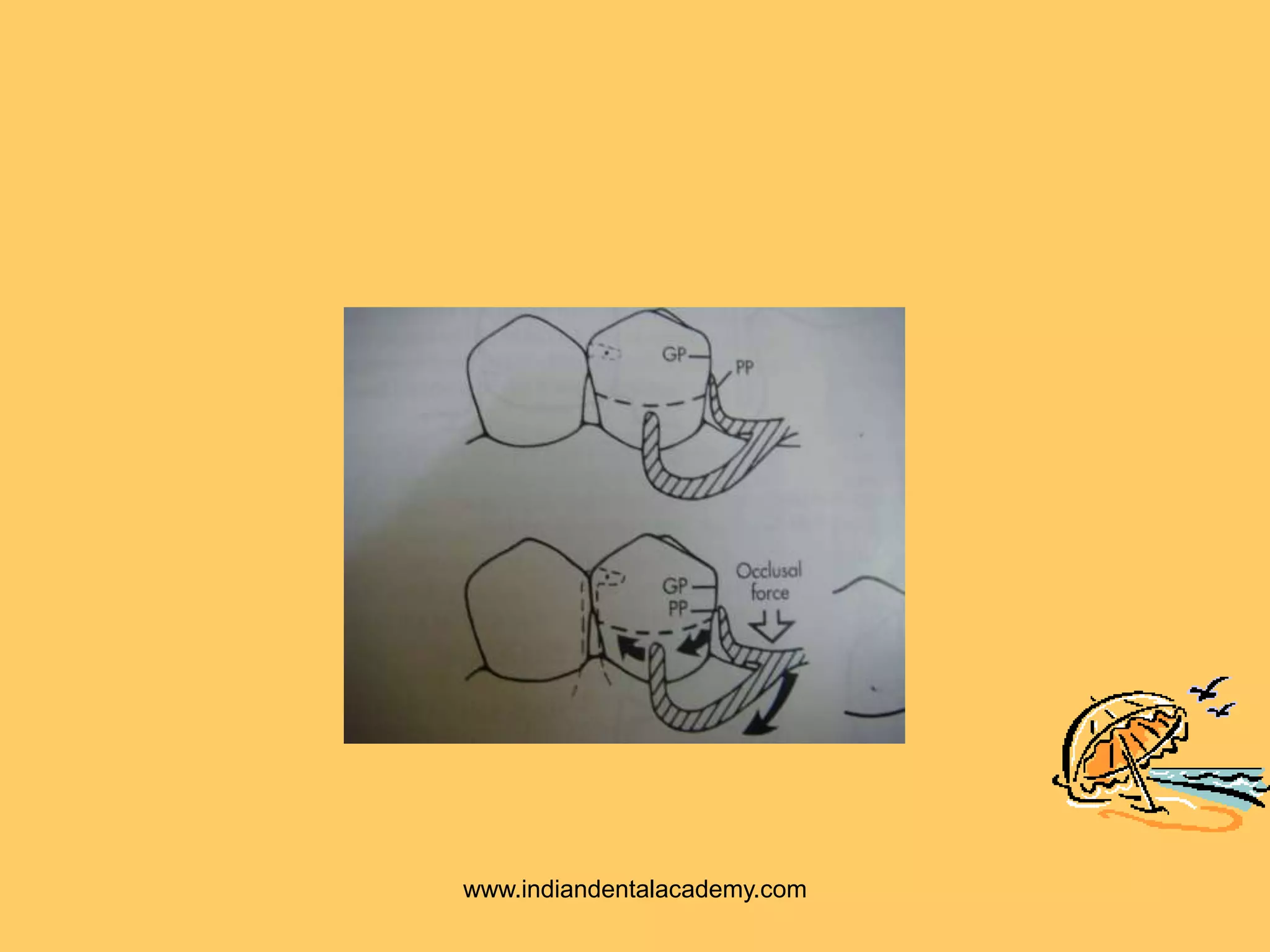


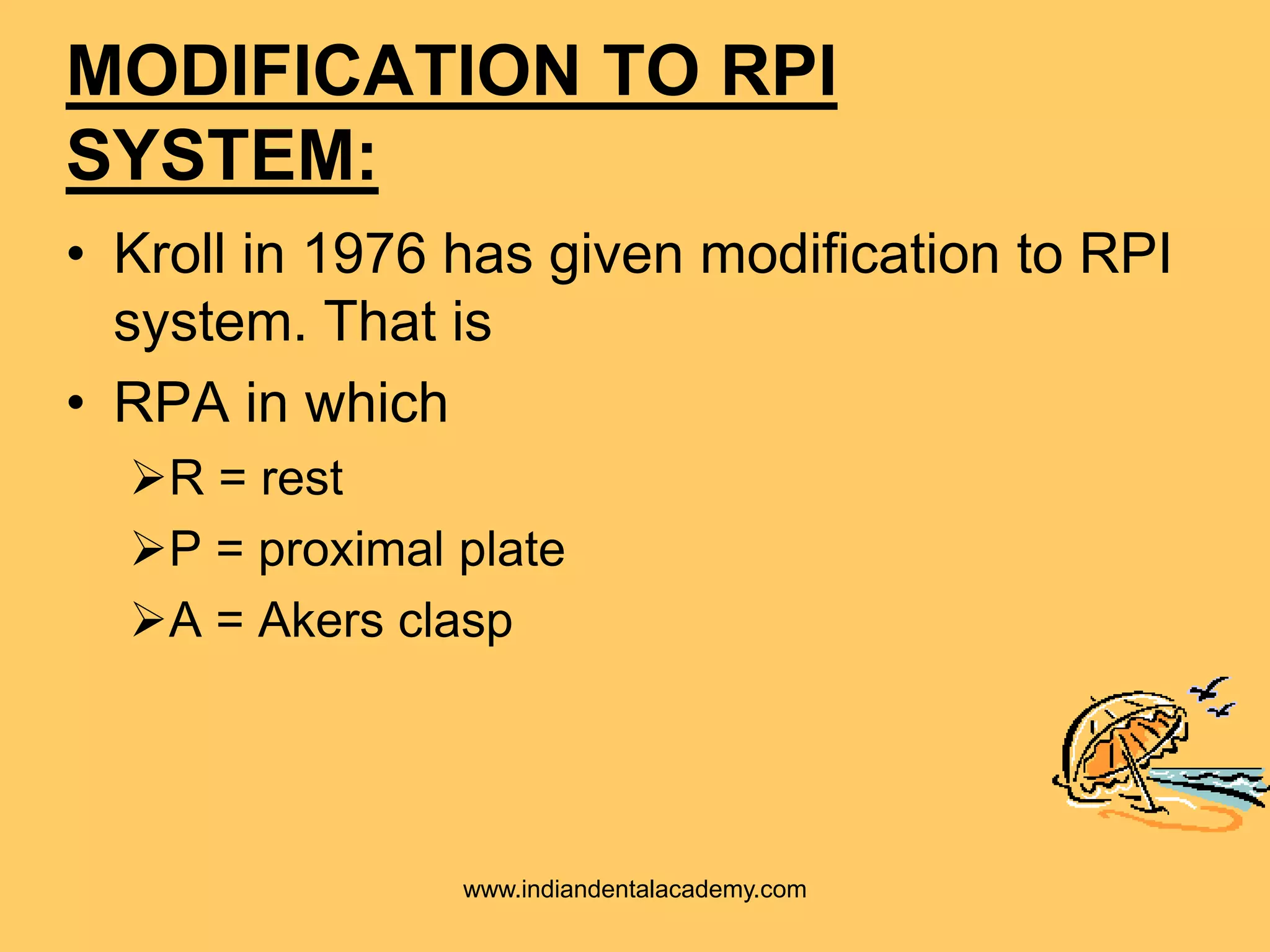
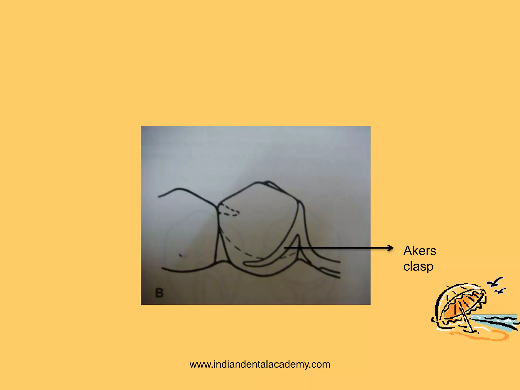


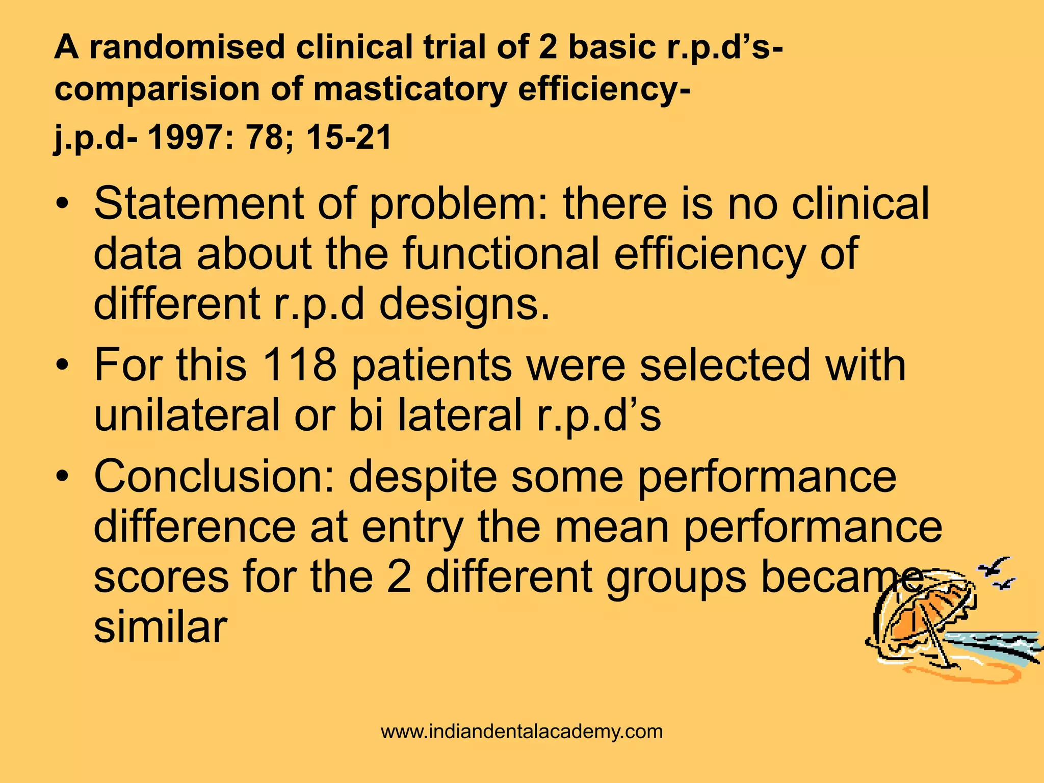


The document discusses the concepts and components of the RPI clasp system for removable partial dentures. The RPI system uses a mesial rest, proximal plate, and I-bar clasp to provide stabilization, retention, and stress control with minimal tooth preparation. There are three approaches to RPI placement depending on how forces are distributed to the tooth and ridge. Modifications include replacing the I-bar with an Akers clasp for teeth with tissue undercuts. Clinical studies found high success rates for RPI dentures and no significant differences in masticatory efficiency between designs.


![RPI System [Autosaved].ppt.;lkjhughgfxdcvbjkl;](https://cdn.slidesharecdn.com/ss_thumbnails/rpisystemautosaved-241021162716-5b5a84ab-thumbnail.jpg?width=640&height=640&fit=bounds)


