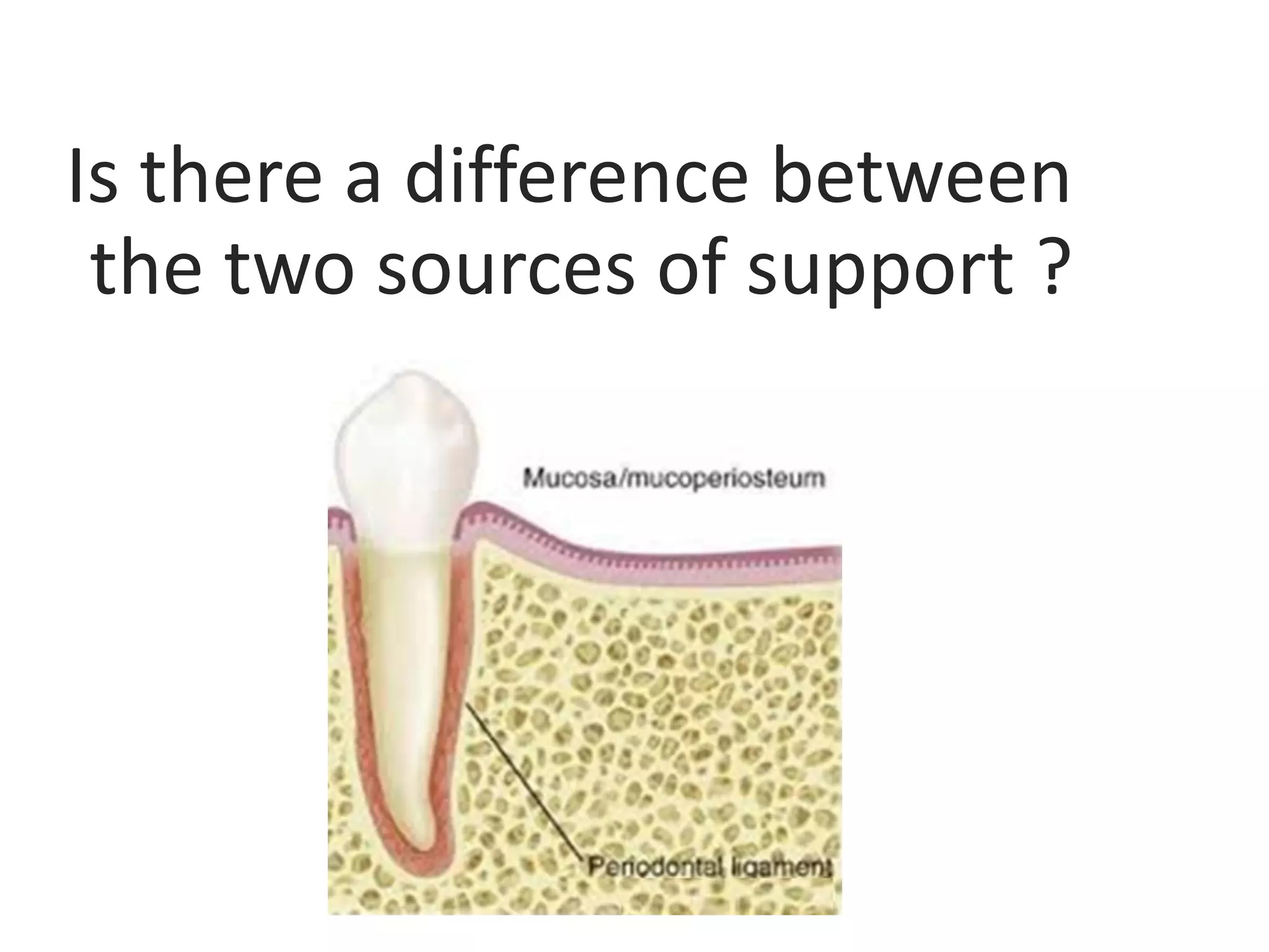
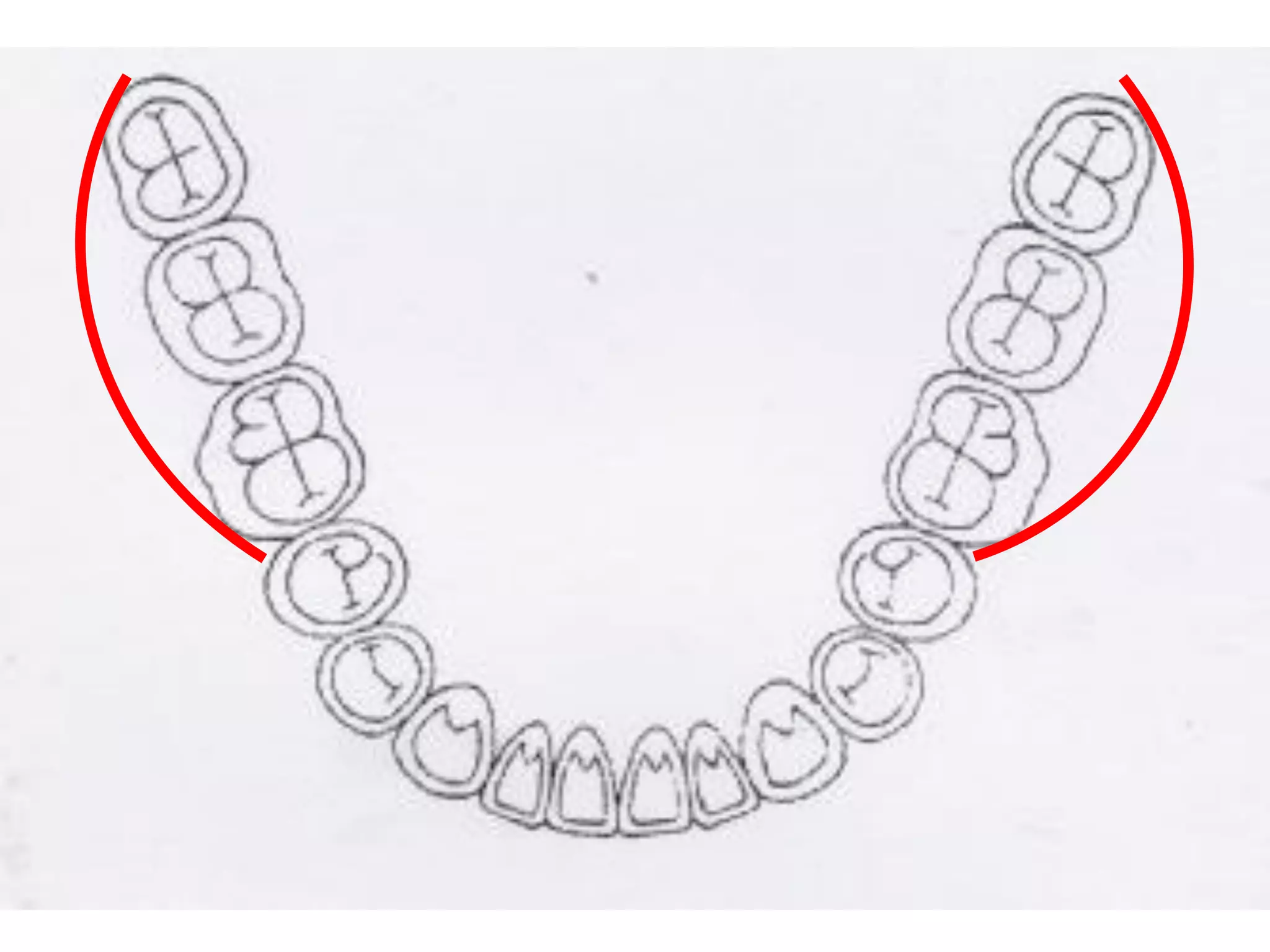
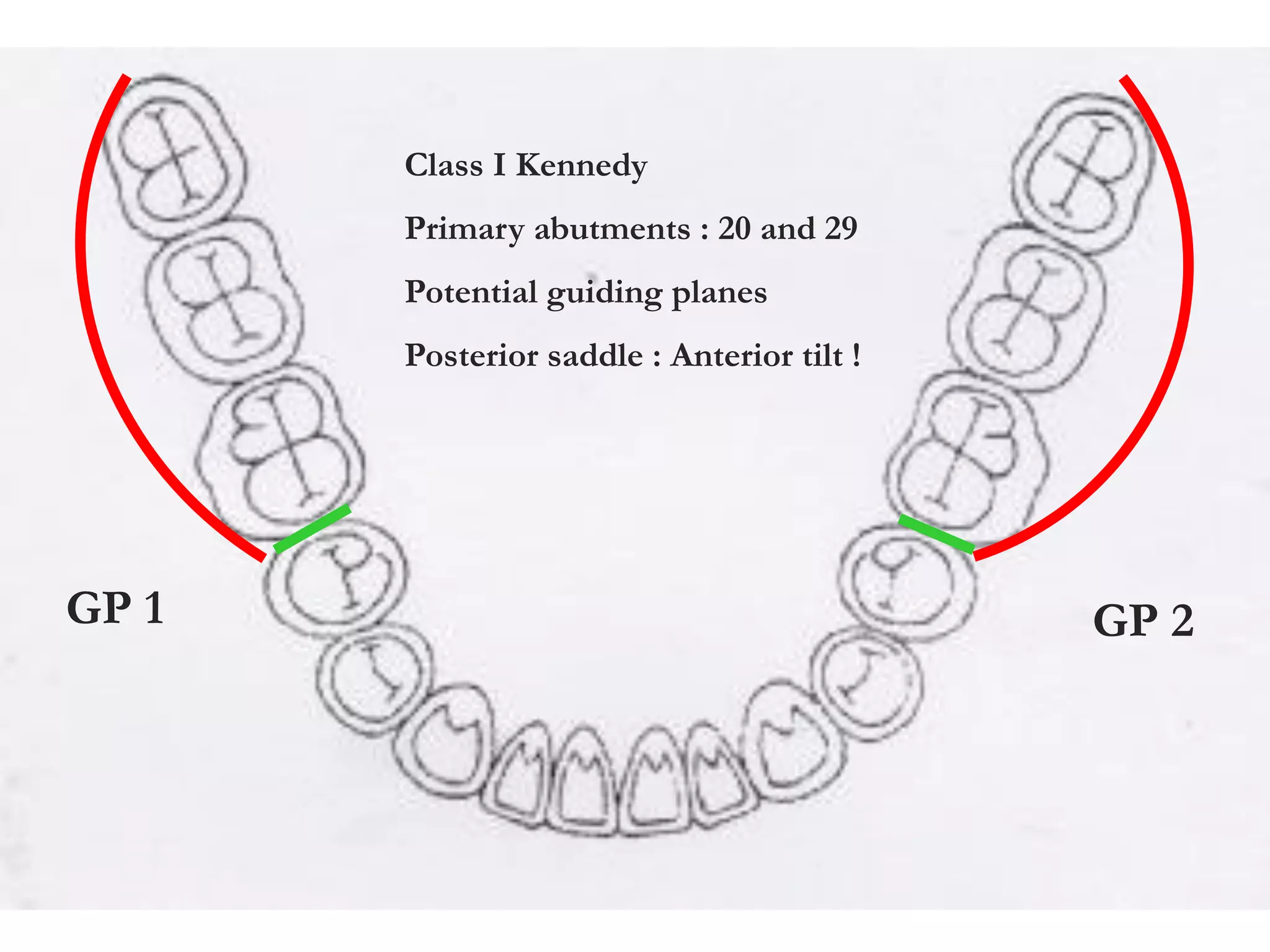
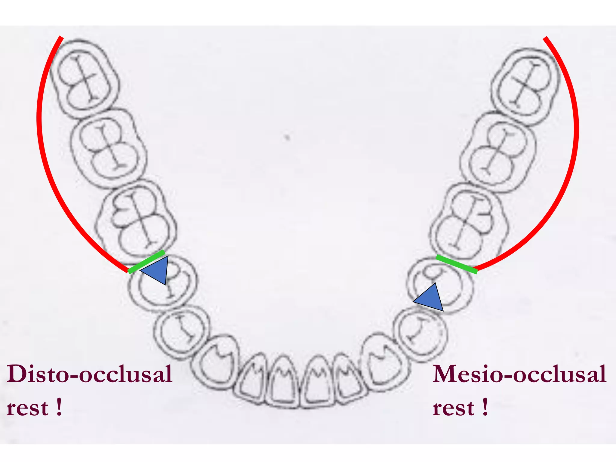
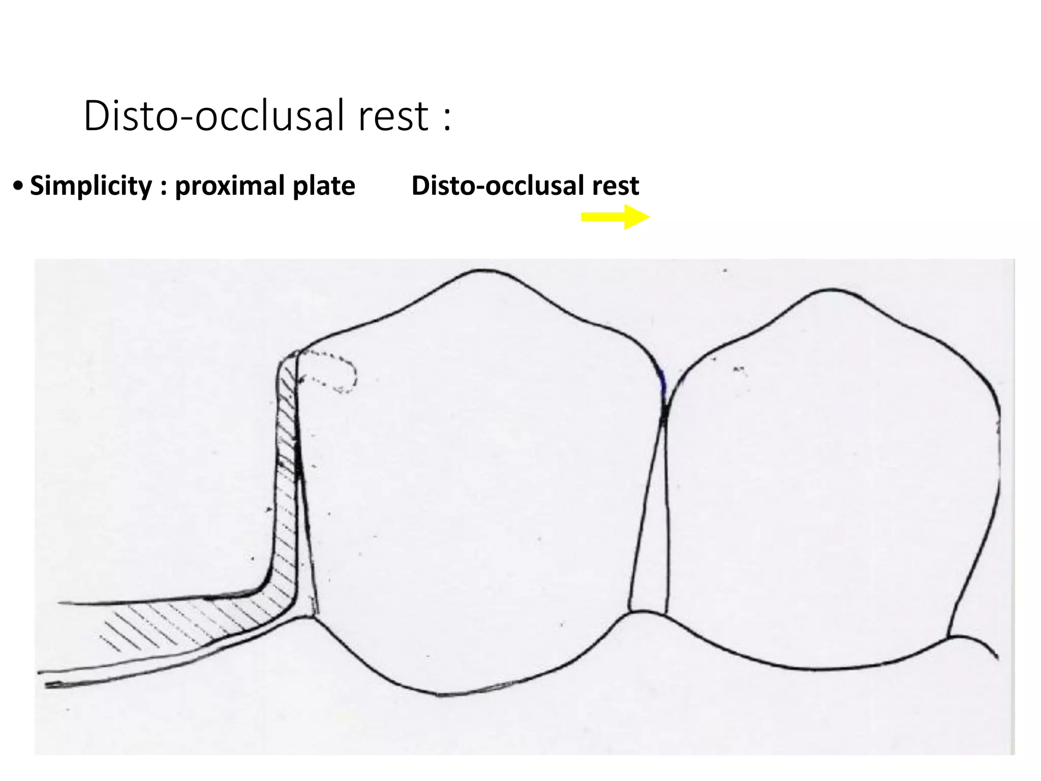
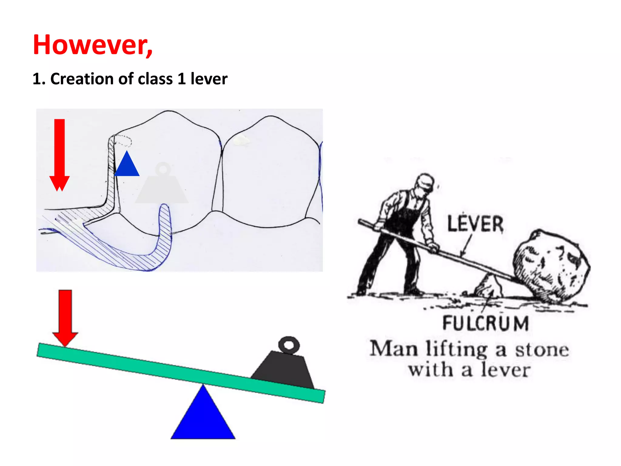
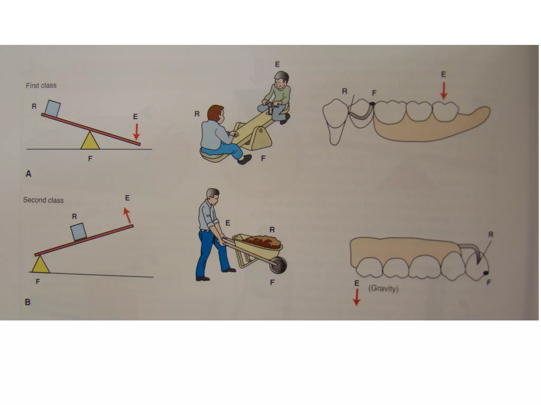
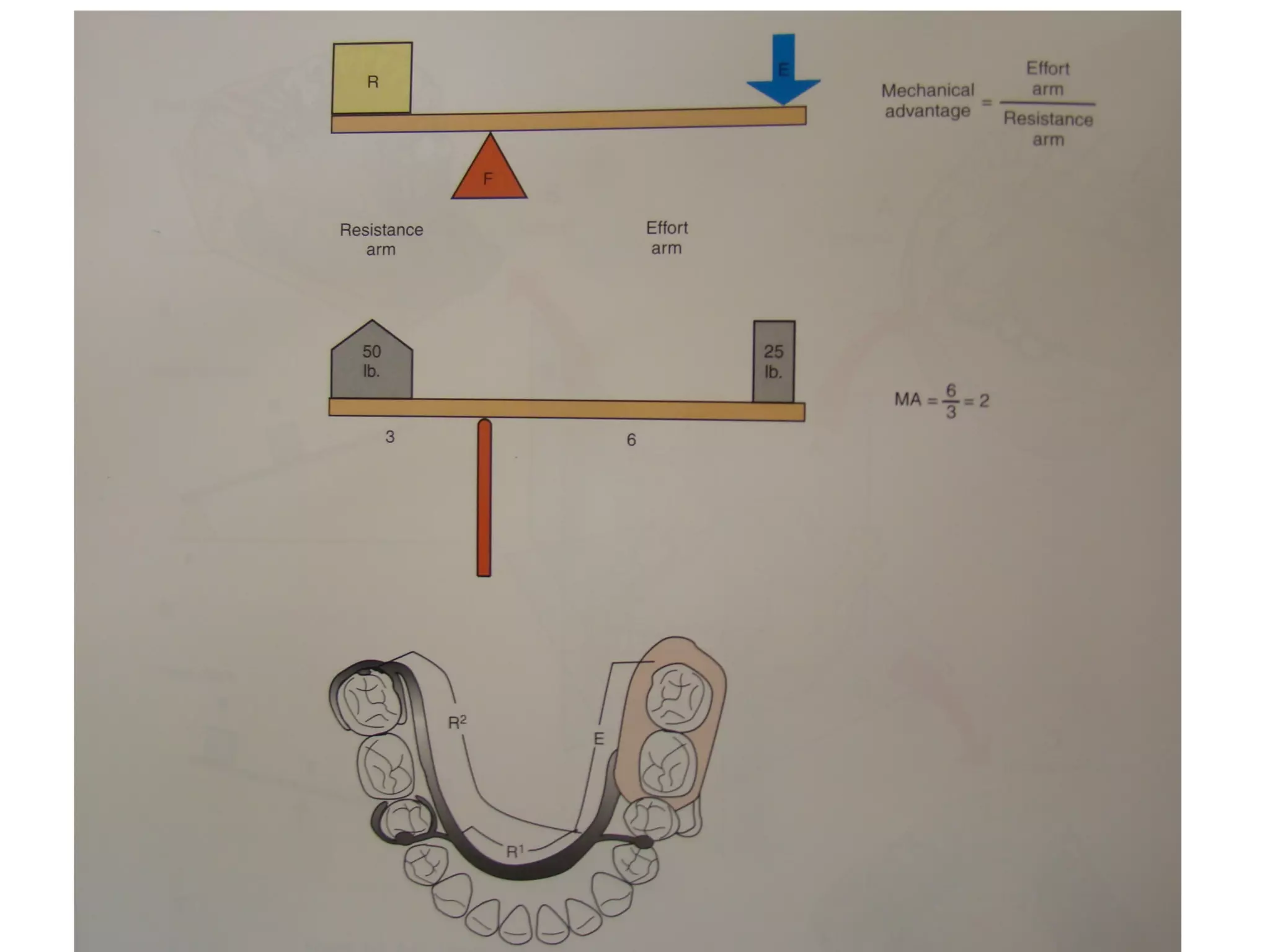
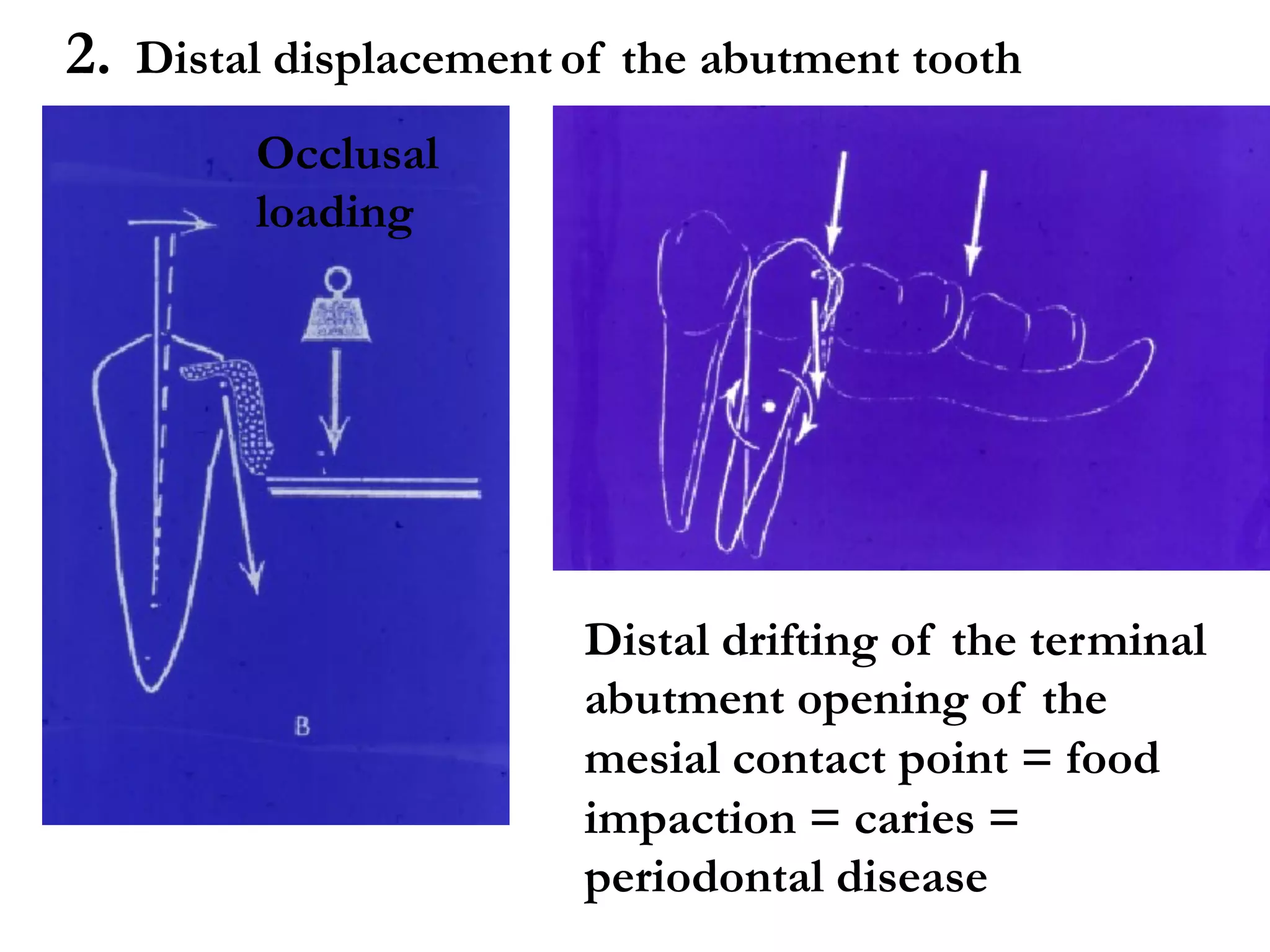
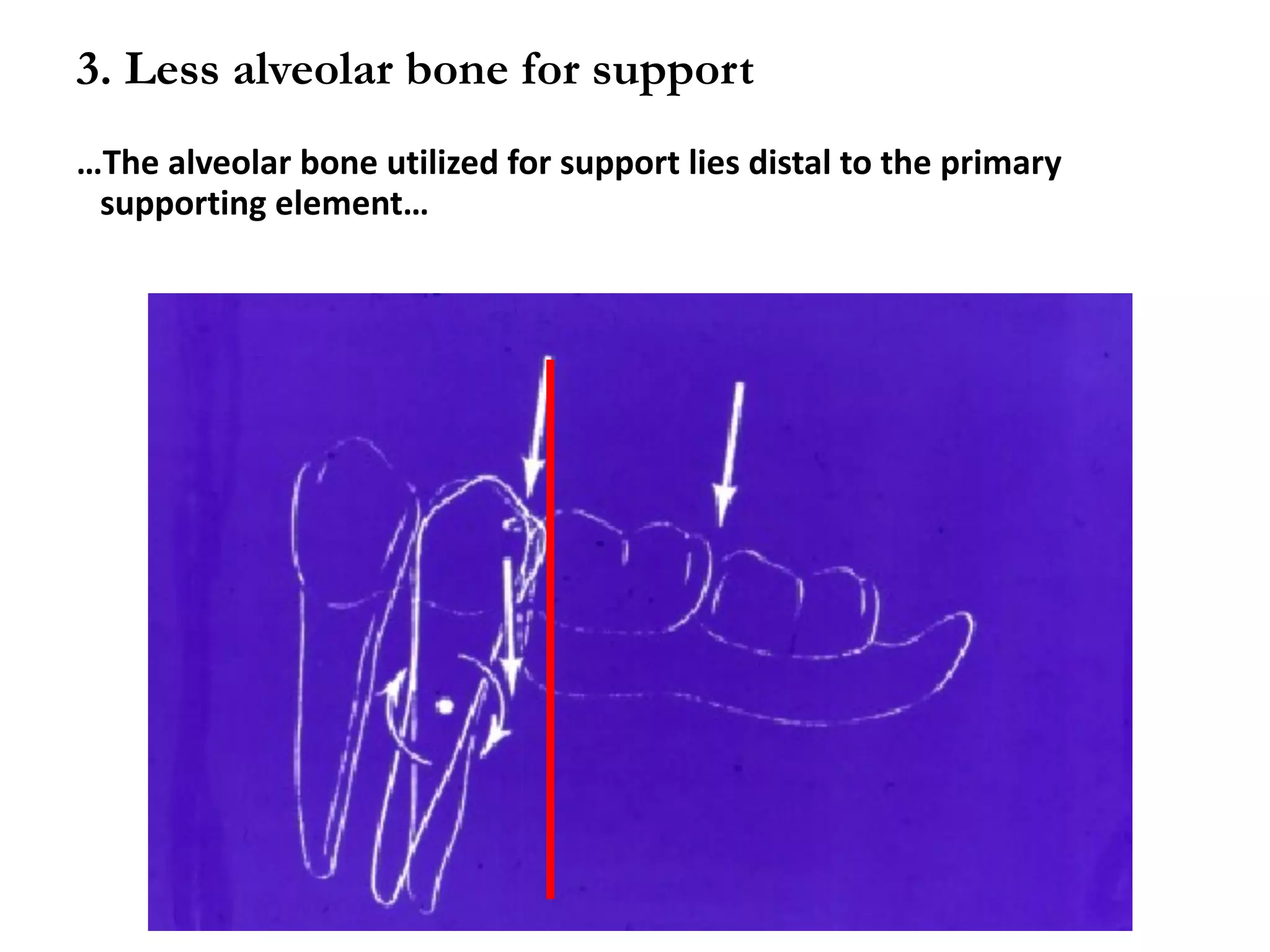
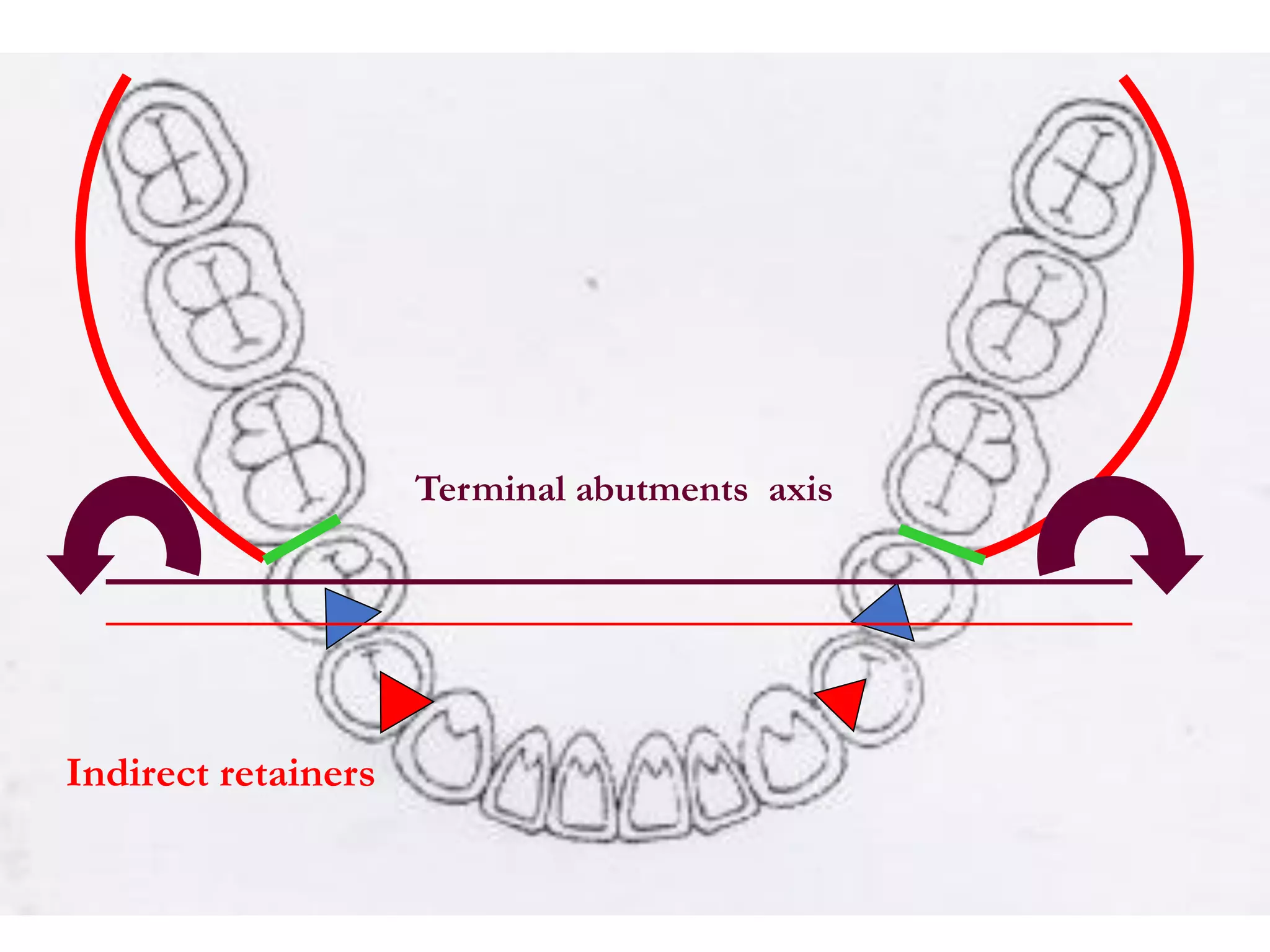
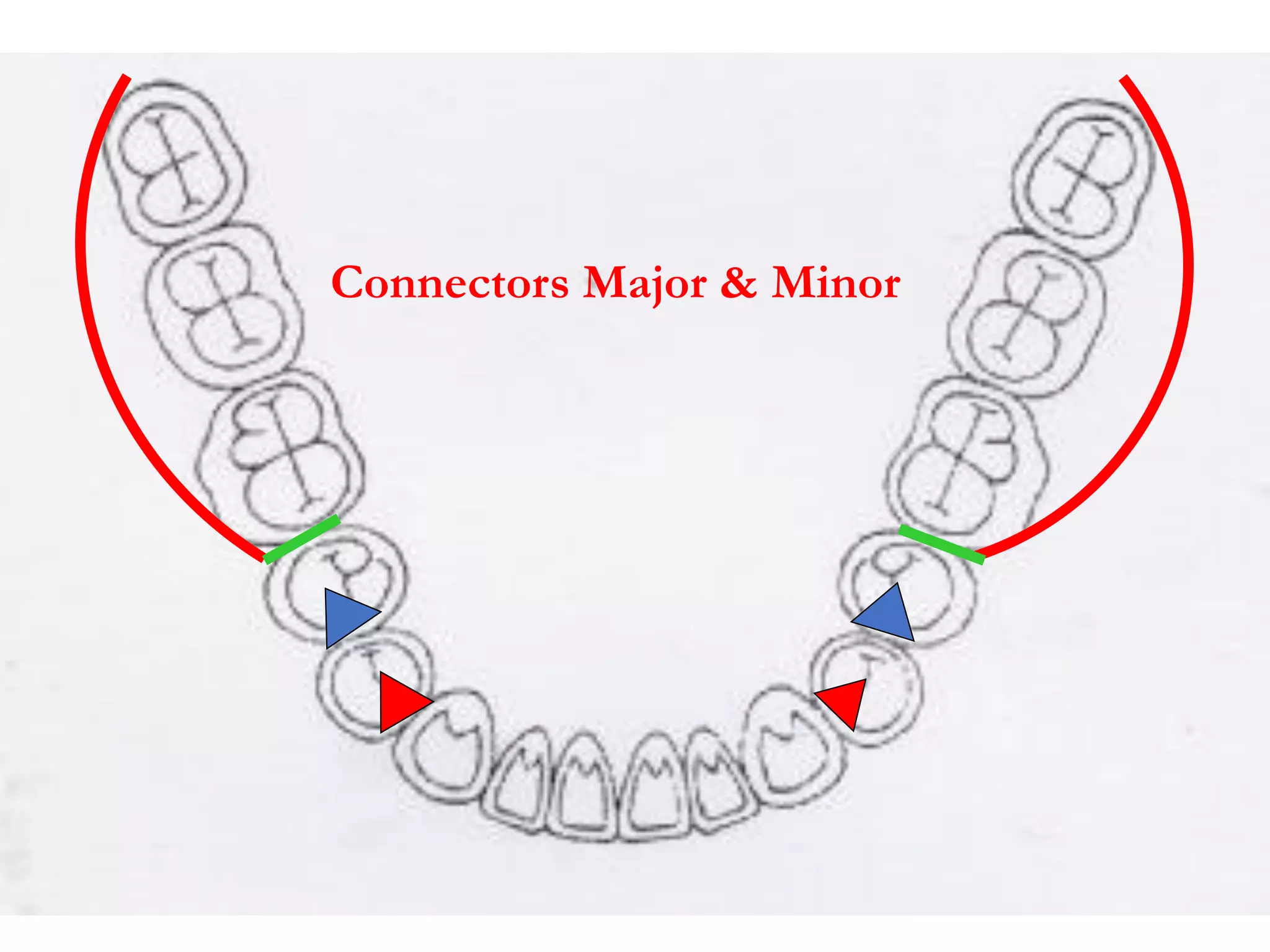
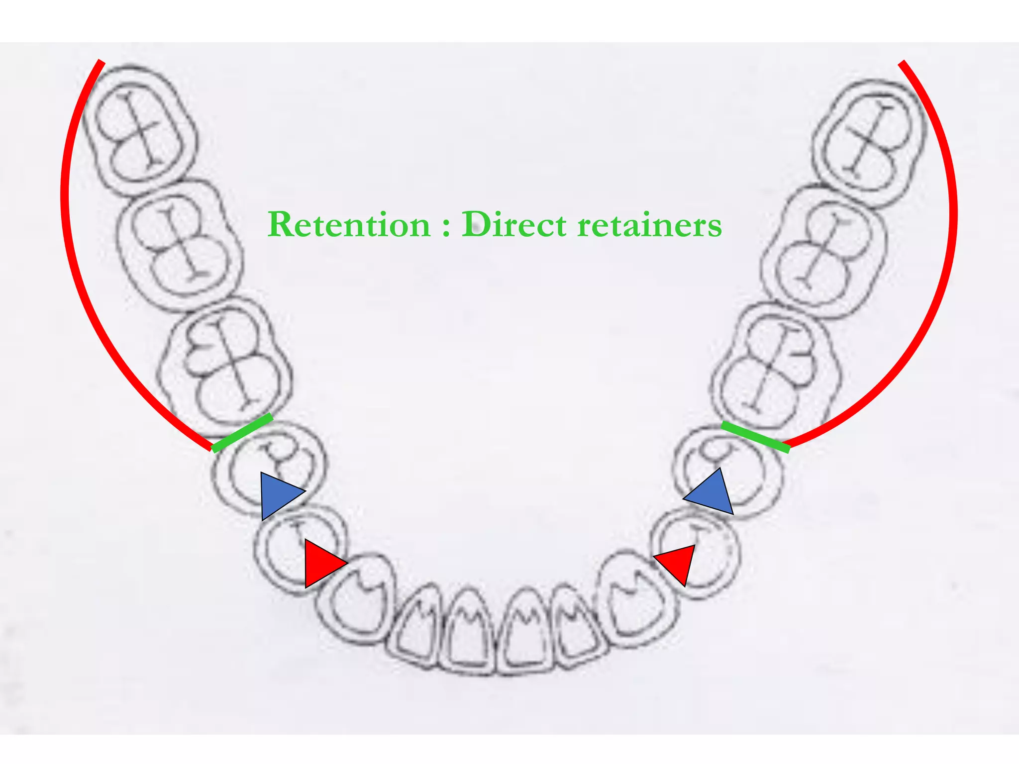
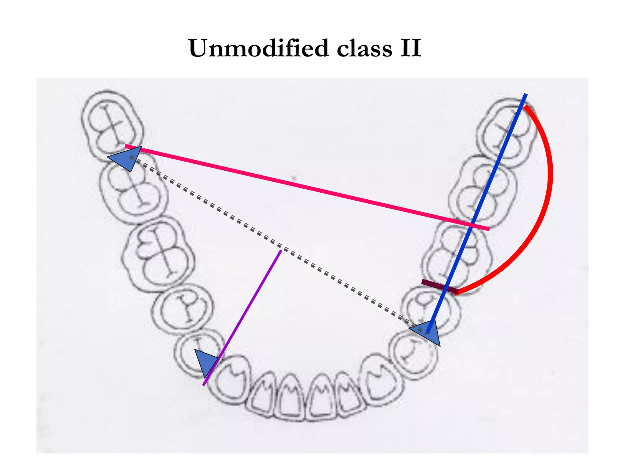
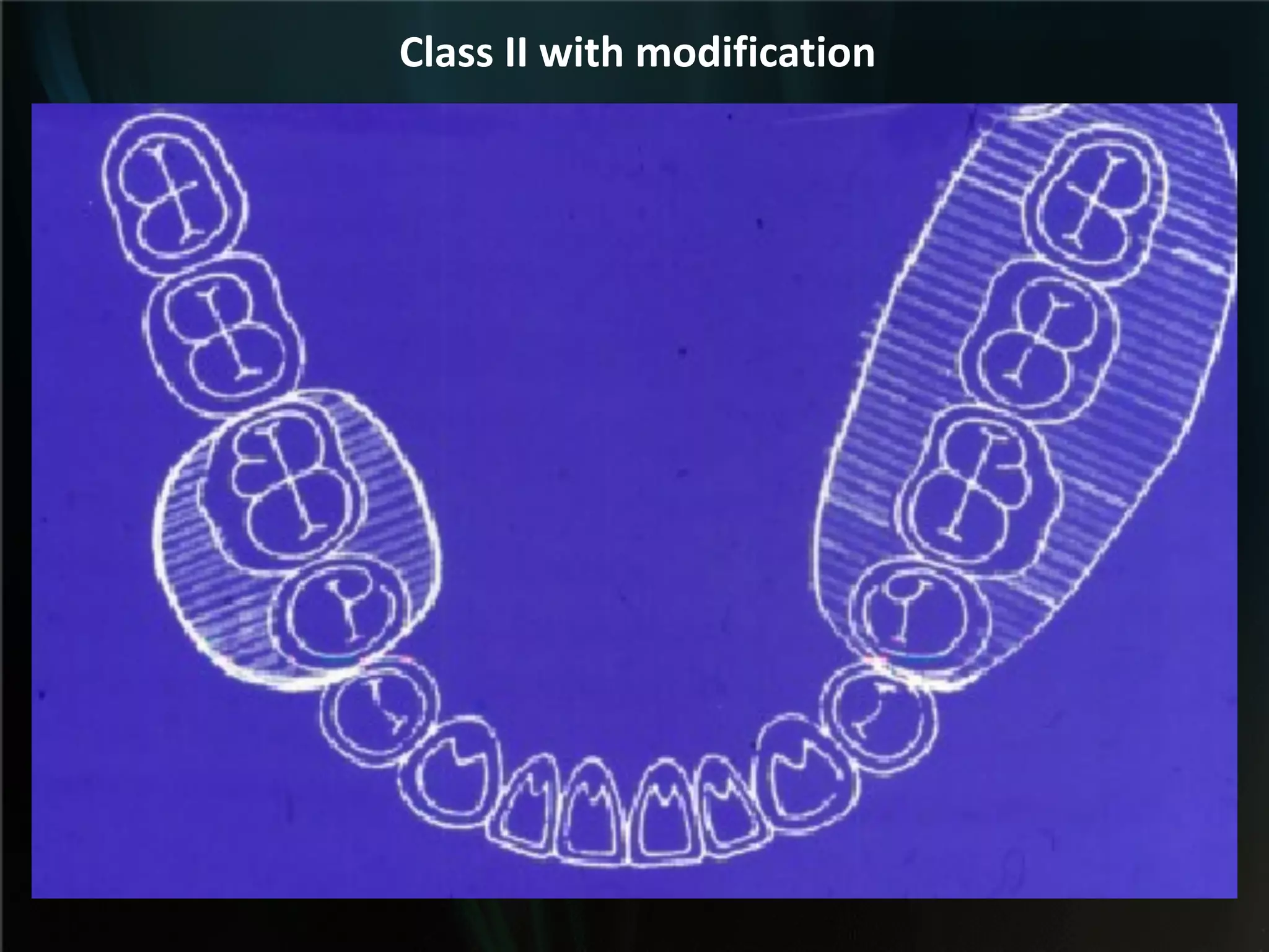
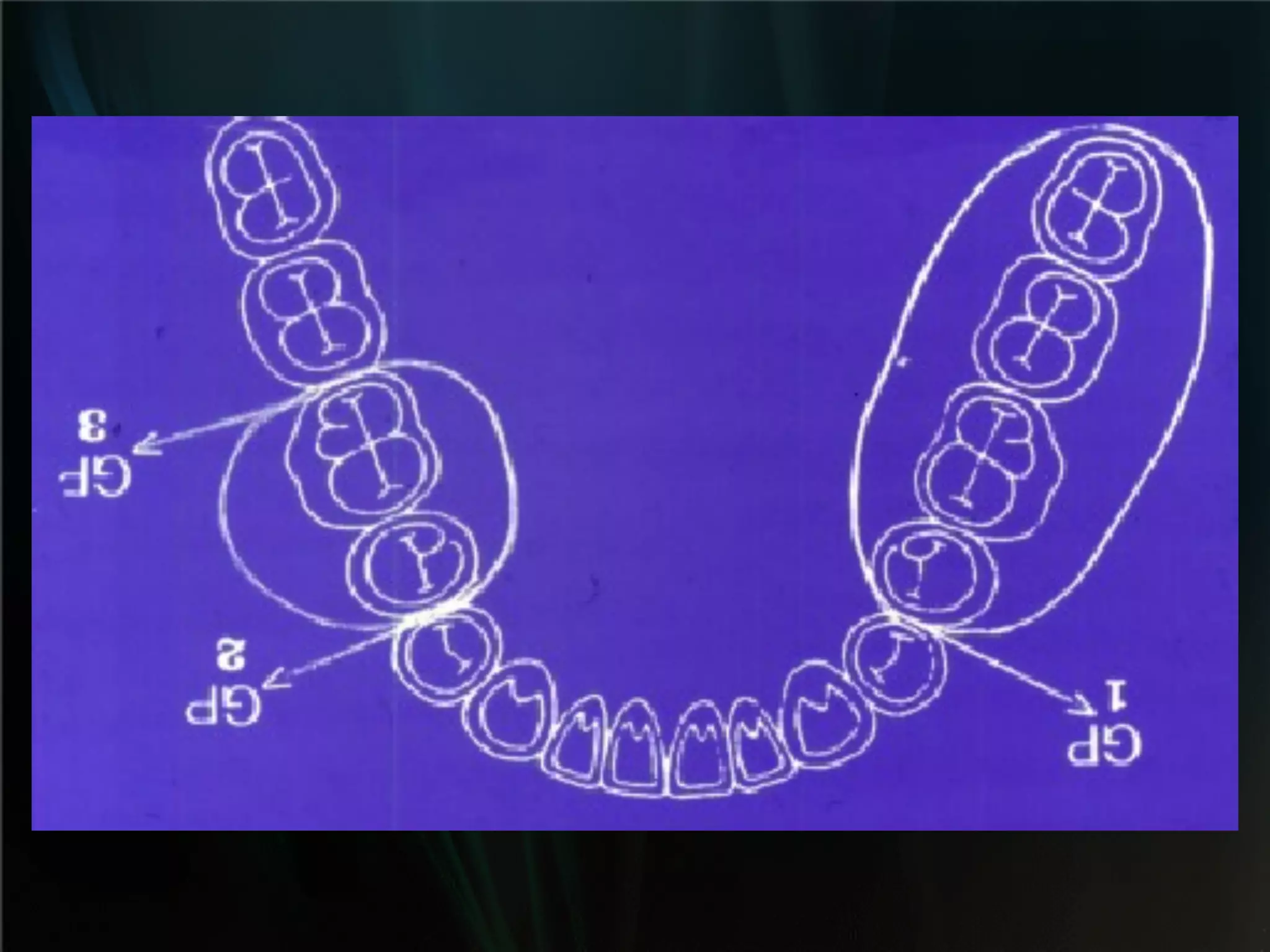
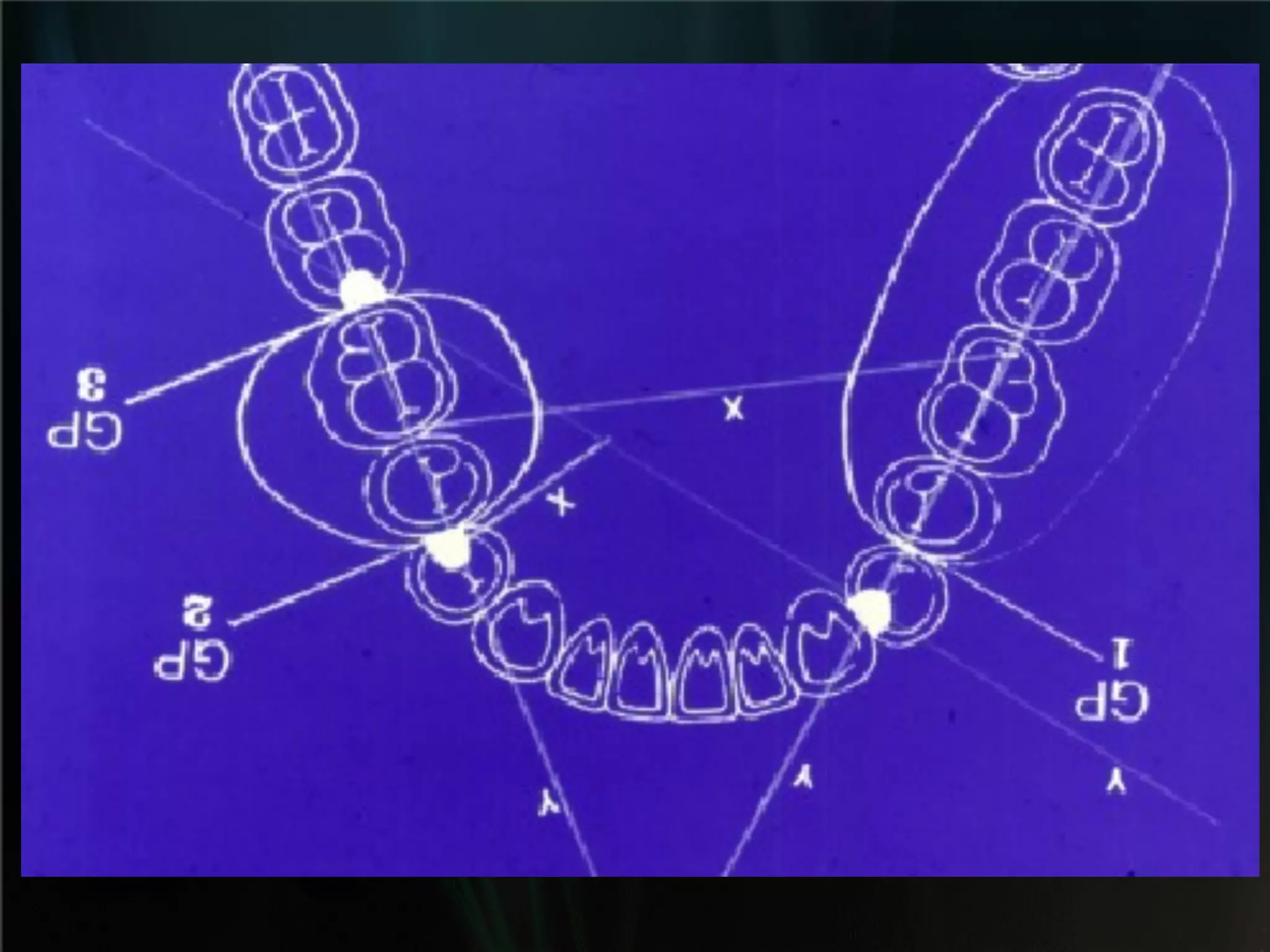
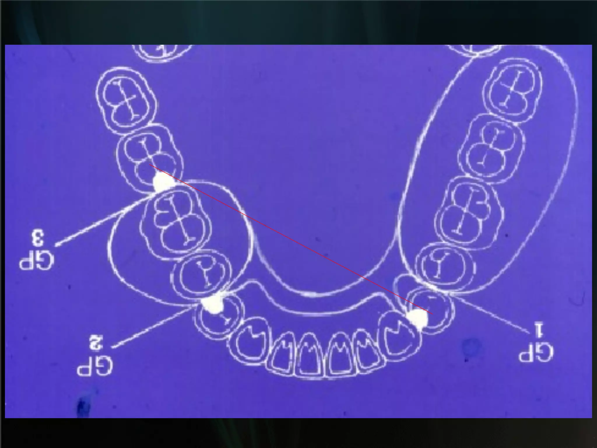
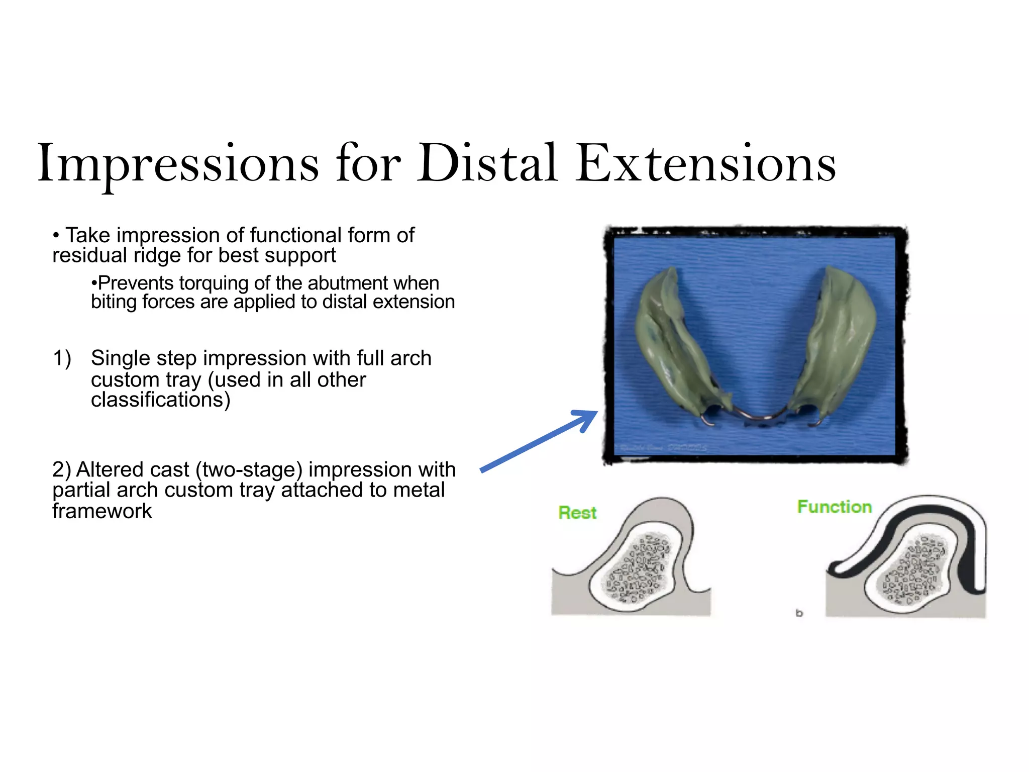
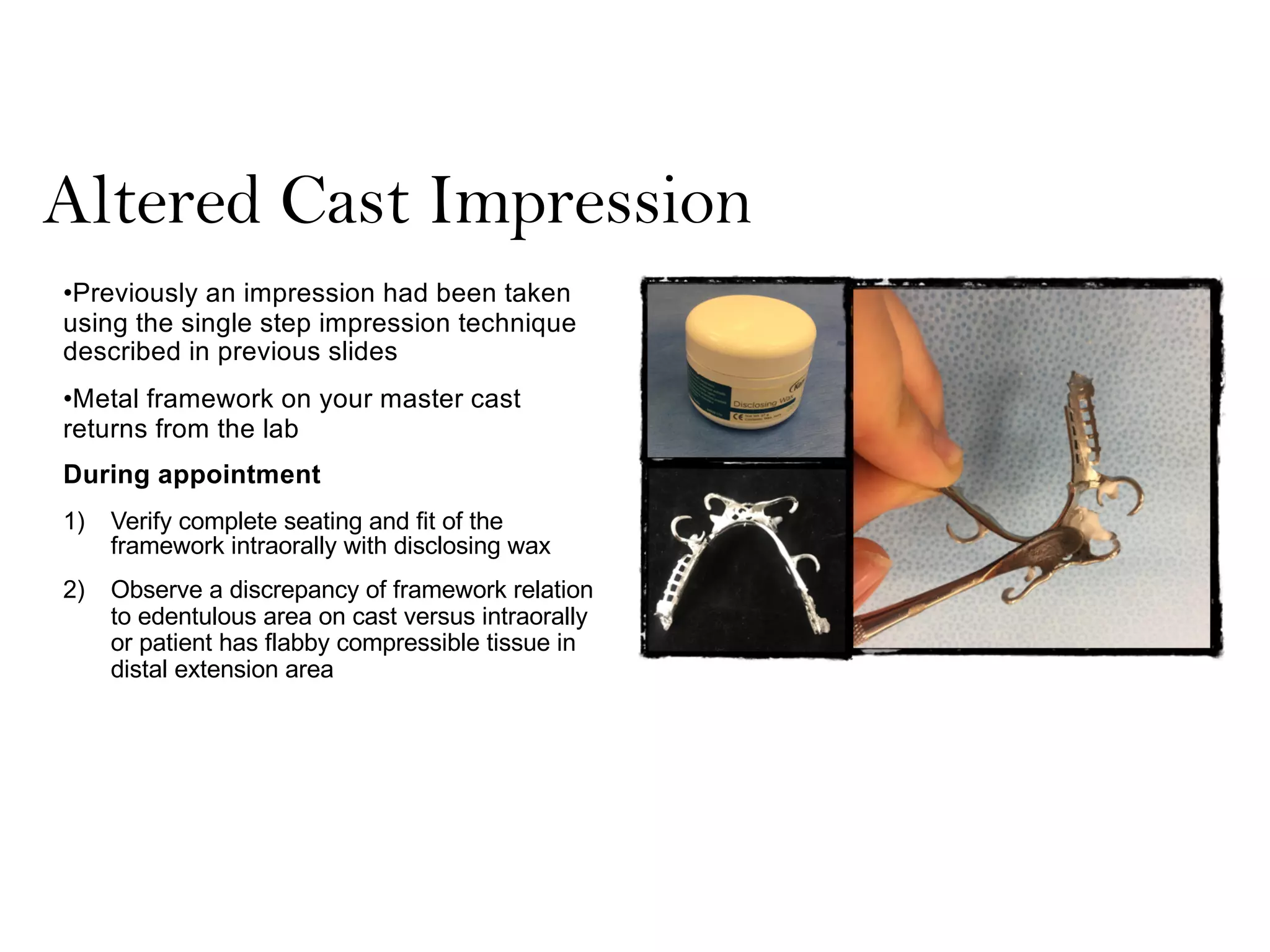
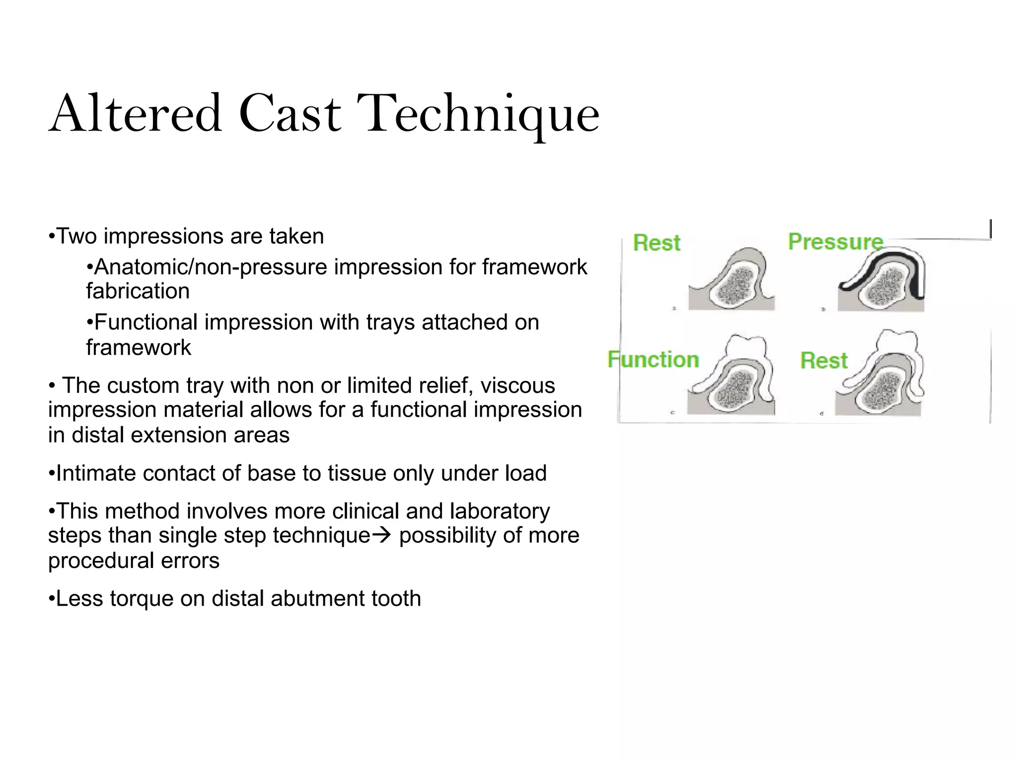
RPD Design Principles
Class I and II
Advanced Prosthodontics
March 25th, 2020
Distal Extension partially edentulous cases:
A) Class I Kennedy classification
B) Class II Kennedy classification
Sources of support
1) Support from the distal extension soft tissue
2) Support from the primary abutment teeth
How are Class I and II cases different?
Is there a difference between
the two sources of support ?
Support of RPD is not equal under occlusal
loading:
-Teeth: Relatively rigid
-Edentulous ridges: Displaceable under force
As a result of this differential support, the RPD
rotates around an axis through the terminal
supporting abutments when occlusal force is
applied to the distal extension
500 microns
resilience of the
residual ridge
tissues.
20 microns of the
teeth permitted by
the PDL
Kennedy Class I and II
Biomechanical principles to be followed:
•Locate the primary axis (fulcrum) of
rotation
•Incorporate direct retainers with stress
releasing design
•Incorporate indirect retention
•Consideration of support from the
extension base
O : Outline the saddle areas :
A decision must be made on which missing teeth require replacement and
saddle areas marked accordingly on an occlusal view of the dental arch
consequently :
•The kennedy classification of the case.
•The primary abutment teeth are determined.
•The number of guiding planes are determined.
•The most appropriate AP tilt is determined.
Class I Kennedy
Primary abutments : 20 and 29
Potential guiding planes
Posterior saddle : Anterior tilt !
GP 1 GP 2
Anterior tilt : exposure of the distal
surfaces of the primary (terminal)
abutments : minimum preparation for
guiding plane achievement.
Anterior tilt : exposure of lingual sulcus
(elimination of undercut) for placement
of major connector.
2) Support from the primary
abutment teeth
Mesio-occlusal
rest !
Disto-occlusal
rest !
Disto-occlusal rest :
•Simplicity : proximal plate Disto-occlusal rest
However,
1. Creation of class 1 lever
Distal drifting of the terminal
abutment opening of the
mesial contact point = food
impaction = caries =
periodontal disease
Occlusal
loading
2. Distal displacement of the abutment tooth
…The alveolar bone utilized for support lies distal to the primary
supporting element…
3. Less alveolar bone for support
Mesio occlusal rest
Additional minor connector
However,
1. Creation of class 2 lever
Occlusal
forces
Occlusal forces will
deactivate the lever
action
2. Mesial displacement of the terminal abutment causing enhancement
of the mesial contact point
3. More alveolar bone utilization of more
alveolar bone for support
4. Stress breaking effect :
Disengagement of primary abutment tooth upon
occlusal load application (short guiding planes)
RPD Rotation around the fulcrum
• D rest, CC Clasp (retentive tip M to rest)
Occluding force on extension base (FF)
Distal rest on rotational axis (R)
Occlusally directed extracting force
vector (single arrow)
• Retentive clasp engages undercut
• Extracting forces placed on abutment tooth
• M rest, CC Clasp (retentive tip D to rest)
Occluding force on extension base (FF)
Mesial rest on rotational axis (R)
Apically directed disengaging force
vector (single arrow)
Clasp tip moves deeper into the undercut
No force is transmitted to abutment tooth
Support axis
2 rests = fulcrum
Indirect
retention is
required
Indirect Retention
•Resistance to movement of the extension
base away from the tissue caused by
masticatory forces (sticky foods), gravity, or
extreme border tissue movements
Indirect Retention
Results from:
• Activation of the retentive element of the primary direct
retainer caused by movement of the extension base away
from the tissue
• The indirect retainer engaging a positive rest seat
Indirect Retention
• True indirect retainers:
• Rest seated in a positive rest seat
• A direct retainer in a proper location (Class II, Mod1)
• Lingual plate major connector supported by rests at each end
Indirect Retention
• Alternate sources of indirect retention
• Should not be sole source of indirect retention
• Unsupported lingual plate major connector
• Max denture base itself
• Rugae support
Terminal abutments axis
Indirect retainers
Connectors Major & Minor
Retention : Direct retainers
Unmodified class II
Class II with modification
RPI System
• R = Mesial Occlusal Rest Seat
• P = Proximal Plate on Distal
• I = I-bar as clasp arm
• I-bar should be located in gingival 1/3 of the buccal surface and
engage .01” undercut
• No more than 2mm of the terminal tip should touch the tooth
Demer JPD 1976
•Proximal plate should have the superior edge on the
survey line in the distal proximal surface and extend
from the DB line angle to slightly past the DL line
angle to provide some lingual reciprocation.
Bar Clasps
• McCracken lists 4 specific indications when a bar clasp arm can be
used
• 1. small degree of undercut (.01”) exists in the cervical 1/3 of tooth
• 2. on abutment teeth for tooth supported RPDs or tooth supported
modification areas
• 3. in distal extension RPDs
• 4. if esthetics is a concern and a cast clasp is indicated
Bar Clasps – When Not to Use
• Severe buccal or lingual tilting
• Severe tissue undercuts
• Shallow buccal vestibule
McCracken Tenth Edition
Guide Plane – to prepare or not to prepare
RPI System - History
• Kratochvil is given credit for developing idea of mesial rest seat,
proximal plate and I-bar in the 1960’s
• “physiologic adjustment” of the casting in the proximal region using rouge
and chloroform
• Krol later gave a name to the system – RPI – and changed a portion of
the preparation for the distal guide plane -1973
• Demer altered the guide plane suggestions from the previous to
using an unprepared plane - 1976
Demer’s article 1976
Kratochvil
Krol
Demer’s Way
No proximal reduction is performed
Mesial rest is used to keep Class II
leverage
I bar engages midbuccal portion of tooth
(ideally)
If soft tissue undercuts are present, use
RPA design by Eliason
Guiding planes length
Full tooth length plane ?
* Interferes with the physiological movements of
the abutment tooth.
* Requires excessive preparation.
-------------------------------------------------------------------
Krol (1973) : 2-3 mm
•Preparation is much simpler.
•Tooth substance is preserved.
•Gingival health is maintained.
•RPD can be inserted more easily.
•Does not interfere with physiological movement of
abutment tooth.
•Stress breaking achievement during loading.
Demer’s Version of RPI
•No guide plane is prepared on the distal proximal
surface. The superior edge of the proximal plate is
placed at the survey line on the distal proximal
surface. The entire infrabuldge (undercut) area is
blocked out as indicated by shading that area on
the tooth
RPA Clasp Design
• A modification of the RPI design
• Designed by Krol and Eliason 1970
• Includes Mesial Rest Seat, Proximal Plate and Akers Clasp
• Used for distal extension RPDs when a soft tissue undercut may exist
or interfere with I clasp
RPA Clasp
RPA Design - Eliason
Akers clasp should only contact tooth along survey line, not above
Don’t forget tissue stops where necessary!
Altered Cast Technique
Impressions for Distal Extensions
• Take impression of functional form of
residual ridge for best support
•Prevents torquing of the abutment when
biting forces are applied to distal extension
1) Single step impression with full arch
custom tray (used in all other
classifications)
2) Altered cast (two-stage) impression with
partial arch custom tray attached to metal
framework
Altered Cast Impression
•Previously an impression had been taken
using the single step impression technique
described in previous slides
•Metal framework on your master cast
returns from the lab
During appointment
1) Verify complete seating and fit of the
framework intraorally with disclosing wax
2) Observe a discrepancy of framework relation
to edentulous area on cast versus intraorally
or patient has flabby compressible tissue in
distal extension area
Altered Cast Impression
3) Vasaline edentulous area on master cast
and add a layer of soft baseplate wax as
spacer for impression material
4) Heat up edentulous side of framework
and fully seat on cast
5) Remove wax on top of the lattice
6) Add a layer of Triad on top of lattice area
2mm short of vestibule to allow space of
bordermolding compound
7) After curing the Triad, remove baseplate
wax
*If Triad is not secure, add a thin layer of
Pattern Resin to secure the custom tray
to the framework
Altered Cast Impression
8) Border mold distal extension areas with
compound
9) Reduce border molding compound to 0.5mm
10) Apply PVS adhesive and wait ten minutes to dry
11) Take impression of distal extension area with
medium or heavy body PVS while border molding
*Make sure rest seats are fully seated and press
on rest seats ONLY, DO NOT press on
distal extension area
12) Send the impression with framework to dental lab
Altered Cast Impression
The dental lab will section your master cast, make retentive undercuts, bead, box and pour the new master
cast, which will be used to process your denture teeth on acrylic base
Dr. Randold Binns
Ffofr.org
Altered Cast Technique
•Two impressions are taken
•Anatomic/non-pressure impression for framework
fabrication
•Functional impression with trays attached on
framework
• The custom tray with non or limited relief, viscous
impression material allows for a functional impression
in distal extension areas
•Intimate contact of base to tissue only under load
•This method involves more clinical and laboratory
steps than single step techniqueà possibility of more
procedural errors
•Less torque on distal abutment tooth
References
• Stewart’s Clinical Removable Partial Prosthodontics Quintessence,
Chicago, IL, 2008.
• Demer, WJ: An analysis of mesial rest-I-bar clasp designs. J Prost
Dent. 36:243-253,1976.
• McCracken’s Removable Partial Prosthodontics., 12th Edition,
Elsevier Mosby, St. Louis, MO, 2015.
• Eliason, CM: RPA clasp design for distal-extension removable partial
dentures. J Prosthet Dent. 49:25-27, 1983.

Basic Principles of RPD design I & II.pdf

  • 1.
    RPD Design Principles ClassI and II Advanced Prosthodontics March 25th, 2020
  • 2.
    Distal Extension partiallyedentulous cases: A) Class I Kennedy classification B) Class II Kennedy classification
  • 3.
    Sources of support 1)Support from the distal extension soft tissue 2) Support from the primary abutment teeth How are Class I and II cases different?
  • 4.
    Is there adifference between the two sources of support ?
  • 5.
    Support of RPDis not equal under occlusal loading: -Teeth: Relatively rigid -Edentulous ridges: Displaceable under force As a result of this differential support, the RPD rotates around an axis through the terminal supporting abutments when occlusal force is applied to the distal extension
  • 6.
    500 microns resilience ofthe residual ridge tissues. 20 microns of the teeth permitted by the PDL
  • 7.
    Kennedy Class Iand II Biomechanical principles to be followed: •Locate the primary axis (fulcrum) of rotation •Incorporate direct retainers with stress releasing design •Incorporate indirect retention •Consideration of support from the extension base
  • 8.
    O : Outlinethe saddle areas : A decision must be made on which missing teeth require replacement and saddle areas marked accordingly on an occlusal view of the dental arch consequently : •The kennedy classification of the case. •The primary abutment teeth are determined. •The number of guiding planes are determined. •The most appropriate AP tilt is determined.
  • 10.
    Class I Kennedy Primaryabutments : 20 and 29 Potential guiding planes Posterior saddle : Anterior tilt ! GP 1 GP 2
  • 11.
    Anterior tilt :exposure of the distal surfaces of the primary (terminal) abutments : minimum preparation for guiding plane achievement.
  • 12.
    Anterior tilt :exposure of lingual sulcus (elimination of undercut) for placement of major connector.
  • 13.
    2) Support fromthe primary abutment teeth
  • 14.
  • 15.
    Disto-occlusal rest : •Simplicity: proximal plate Disto-occlusal rest
  • 16.
  • 19.
    Distal drifting ofthe terminal abutment opening of the mesial contact point = food impaction = caries = periodontal disease Occlusal loading 2. Distal displacement of the abutment tooth
  • 20.
    …The alveolar boneutilized for support lies distal to the primary supporting element… 3. Less alveolar bone for support
  • 21.
  • 22.
    However, 1. Creation ofclass 2 lever Occlusal forces Occlusal forces will deactivate the lever action
  • 23.
    2. Mesial displacementof the terminal abutment causing enhancement of the mesial contact point
  • 24.
    3. More alveolarbone utilization of more alveolar bone for support
  • 25.
    4. Stress breakingeffect : Disengagement of primary abutment tooth upon occlusal load application (short guiding planes)
  • 26.
    RPD Rotation aroundthe fulcrum • D rest, CC Clasp (retentive tip M to rest) Occluding force on extension base (FF) Distal rest on rotational axis (R) Occlusally directed extracting force vector (single arrow) • Retentive clasp engages undercut • Extracting forces placed on abutment tooth
  • 27.
    • M rest,CC Clasp (retentive tip D to rest) Occluding force on extension base (FF) Mesial rest on rotational axis (R) Apically directed disengaging force vector (single arrow) Clasp tip moves deeper into the undercut No force is transmitted to abutment tooth
  • 28.
  • 30.
  • 31.
    Indirect Retention •Resistance tomovement of the extension base away from the tissue caused by masticatory forces (sticky foods), gravity, or extreme border tissue movements
  • 32.
    Indirect Retention Results from: •Activation of the retentive element of the primary direct retainer caused by movement of the extension base away from the tissue • The indirect retainer engaging a positive rest seat
  • 33.
    Indirect Retention • Trueindirect retainers: • Rest seated in a positive rest seat • A direct retainer in a proper location (Class II, Mod1) • Lingual plate major connector supported by rests at each end
  • 34.
    Indirect Retention • Alternatesources of indirect retention • Should not be sole source of indirect retention • Unsupported lingual plate major connector • Max denture base itself • Rugae support
  • 35.
  • 36.
  • 37.
  • 39.
  • 40.
    Class II withmodification
  • 44.
    RPI System • R= Mesial Occlusal Rest Seat • P = Proximal Plate on Distal • I = I-bar as clasp arm • I-bar should be located in gingival 1/3 of the buccal surface and engage .01” undercut • No more than 2mm of the terminal tip should touch the tooth Demer JPD 1976
  • 45.
    •Proximal plate shouldhave the superior edge on the survey line in the distal proximal surface and extend from the DB line angle to slightly past the DL line angle to provide some lingual reciprocation.
  • 46.
    Bar Clasps • McCrackenlists 4 specific indications when a bar clasp arm can be used • 1. small degree of undercut (.01”) exists in the cervical 1/3 of tooth • 2. on abutment teeth for tooth supported RPDs or tooth supported modification areas • 3. in distal extension RPDs • 4. if esthetics is a concern and a cast clasp is indicated
  • 47.
    Bar Clasps –When Not to Use • Severe buccal or lingual tilting • Severe tissue undercuts • Shallow buccal vestibule McCracken Tenth Edition
  • 48.
    Guide Plane –to prepare or not to prepare
  • 49.
    RPI System -History • Kratochvil is given credit for developing idea of mesial rest seat, proximal plate and I-bar in the 1960’s • “physiologic adjustment” of the casting in the proximal region using rouge and chloroform • Krol later gave a name to the system – RPI – and changed a portion of the preparation for the distal guide plane -1973 • Demer altered the guide plane suggestions from the previous to using an unprepared plane - 1976
  • 50.
  • 51.
    Demer’s Way No proximalreduction is performed Mesial rest is used to keep Class II leverage I bar engages midbuccal portion of tooth (ideally) If soft tissue undercuts are present, use RPA design by Eliason
  • 52.
    Guiding planes length Fulltooth length plane ? * Interferes with the physiological movements of the abutment tooth. * Requires excessive preparation. ------------------------------------------------------------------- Krol (1973) : 2-3 mm •Preparation is much simpler. •Tooth substance is preserved. •Gingival health is maintained. •RPD can be inserted more easily. •Does not interfere with physiological movement of abutment tooth. •Stress breaking achievement during loading.
  • 53.
    Demer’s Version ofRPI •No guide plane is prepared on the distal proximal surface. The superior edge of the proximal plate is placed at the survey line on the distal proximal surface. The entire infrabuldge (undercut) area is blocked out as indicated by shading that area on the tooth
  • 54.
    RPA Clasp Design •A modification of the RPI design • Designed by Krol and Eliason 1970 • Includes Mesial Rest Seat, Proximal Plate and Akers Clasp • Used for distal extension RPDs when a soft tissue undercut may exist or interfere with I clasp RPA Clasp
  • 55.
    RPA Design -Eliason Akers clasp should only contact tooth along survey line, not above
  • 57.
    Don’t forget tissuestops where necessary!
  • 60.
  • 61.
    Impressions for DistalExtensions • Take impression of functional form of residual ridge for best support •Prevents torquing of the abutment when biting forces are applied to distal extension 1) Single step impression with full arch custom tray (used in all other classifications) 2) Altered cast (two-stage) impression with partial arch custom tray attached to metal framework
  • 62.
    Altered Cast Impression •Previouslyan impression had been taken using the single step impression technique described in previous slides •Metal framework on your master cast returns from the lab During appointment 1) Verify complete seating and fit of the framework intraorally with disclosing wax 2) Observe a discrepancy of framework relation to edentulous area on cast versus intraorally or patient has flabby compressible tissue in distal extension area
  • 63.
    Altered Cast Impression 3)Vasaline edentulous area on master cast and add a layer of soft baseplate wax as spacer for impression material 4) Heat up edentulous side of framework and fully seat on cast 5) Remove wax on top of the lattice 6) Add a layer of Triad on top of lattice area 2mm short of vestibule to allow space of bordermolding compound 7) After curing the Triad, remove baseplate wax *If Triad is not secure, add a thin layer of Pattern Resin to secure the custom tray to the framework
  • 64.
    Altered Cast Impression 8)Border mold distal extension areas with compound 9) Reduce border molding compound to 0.5mm 10) Apply PVS adhesive and wait ten minutes to dry 11) Take impression of distal extension area with medium or heavy body PVS while border molding *Make sure rest seats are fully seated and press on rest seats ONLY, DO NOT press on distal extension area 12) Send the impression with framework to dental lab
  • 65.
    Altered Cast Impression Thedental lab will section your master cast, make retentive undercuts, bead, box and pour the new master cast, which will be used to process your denture teeth on acrylic base Dr. Randold Binns Ffofr.org
  • 66.
    Altered Cast Technique •Twoimpressions are taken •Anatomic/non-pressure impression for framework fabrication •Functional impression with trays attached on framework • The custom tray with non or limited relief, viscous impression material allows for a functional impression in distal extension areas •Intimate contact of base to tissue only under load •This method involves more clinical and laboratory steps than single step techniqueà possibility of more procedural errors •Less torque on distal abutment tooth
  • 67.
    References • Stewart’s ClinicalRemovable Partial Prosthodontics Quintessence, Chicago, IL, 2008. • Demer, WJ: An analysis of mesial rest-I-bar clasp designs. J Prost Dent. 36:243-253,1976. • McCracken’s Removable Partial Prosthodontics., 12th Edition, Elsevier Mosby, St. Louis, MO, 2015. • Eliason, CM: RPA clasp design for distal-extension removable partial dentures. J Prosthet Dent. 49:25-27, 1983.