This document provides an overview of implant supported overdentures, including definitions, history, indications, contraindications, advantages, disadvantages, treatment options, and procedures. Key points discussed include:
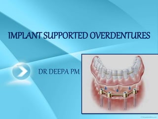
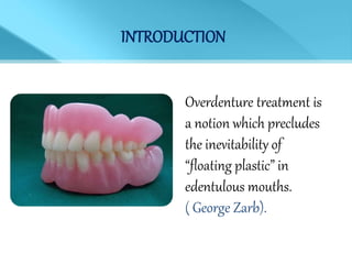
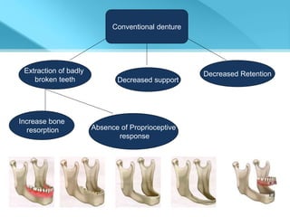
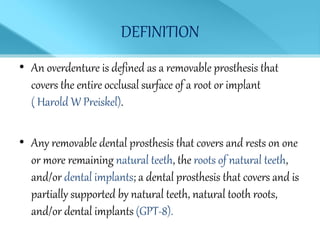
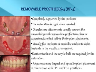
- Overdentures are removable prostheses that cover natural tooth roots, implants, or both for support.
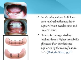
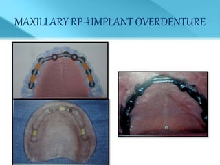
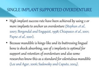
- Implant supported overdentures have better outcomes than conventional dentures or overdentures supported only by natural tooth roots.
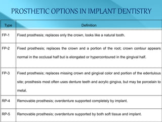
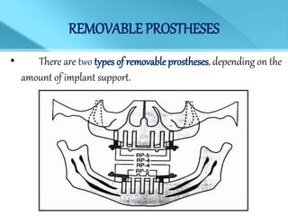
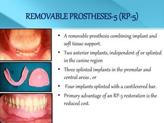
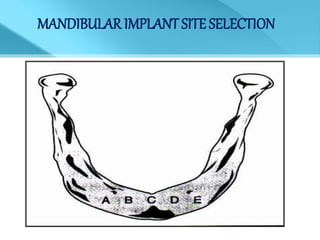
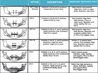
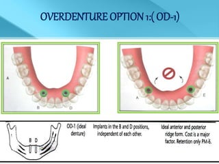
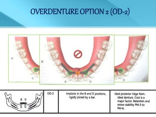
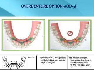
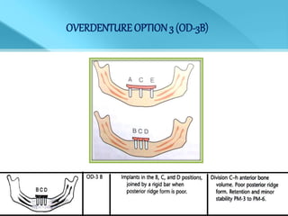
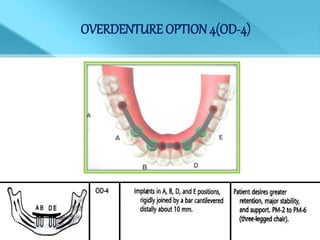
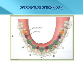
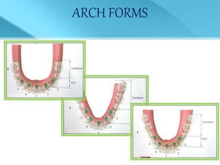
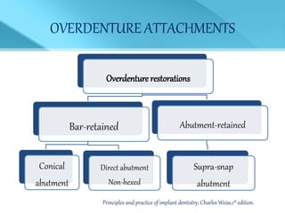
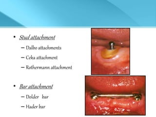
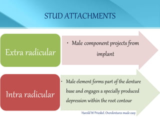
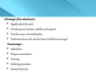
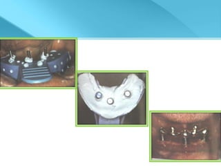
- Treatment options depend on factors like jaw, bone quality, number of implants, and can involve bar-retained or independent attachments.
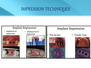
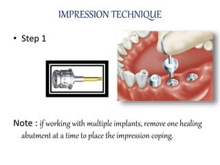
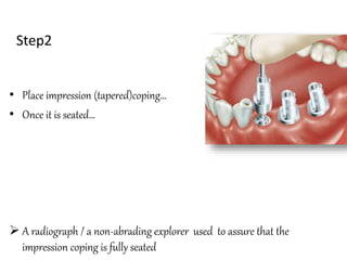
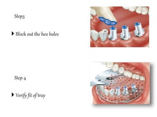
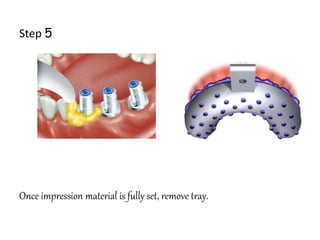
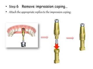
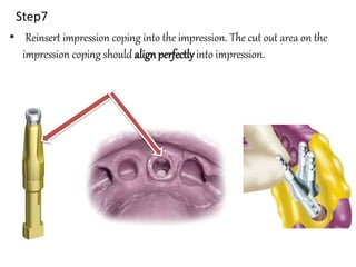
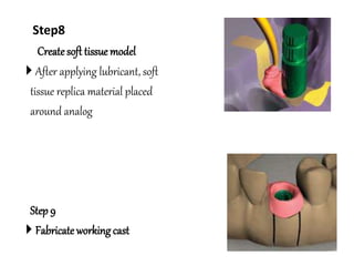
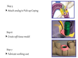
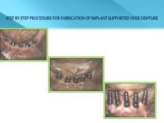
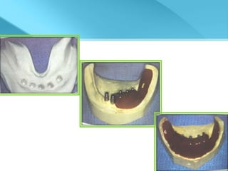
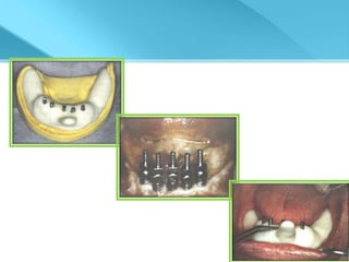
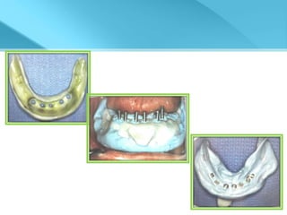
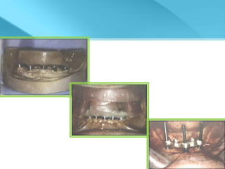
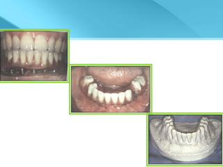
- Procedures involve medical evaluation, treatment planning, transitional dentures, surgical placement, attachment connection, and definitive prosthesis fabrication