SlideShare a Scribd company logo
1 of 16
Download to read offline
SUBJECT: CN
DCN-ErrorDetection&Correction
There are many reasons such as noise, cross-talk etc., which may help data to get corrupted
during transmission. The upper layers work on some generalized view of network architecture
and are not aware of actual hardware data processing.Hence, the upper layers expect error-free
transmission between the systems. Most of the applications would not function expectedly if
they receive erroneous data. Applications such as voice and video may not be that affected and
with some errors they may still function well.
Data-link layer uses some error control mechanism to ensure that frames (data bit streams) are
transmitted with certain level of accuracy. But to understand how errors is controlled, it is
essential to know what types of errors may occur.
TypesofErrors
There may be three types of errors:
• Single bit error
In a frame, there is only one bit, anywhere though, which is corrupt.
• Multiple bits error
Frame is received with more than one bits in corrupted state.
• Burst error
• Frame contains more than1 consecutive bits corrupted.
Error control mechanism may involve two possible ways:
• Error detection
• Error correction
ErrorDetection
Errors in the received frames are detected by means of Parity Check and Cyclic Redundancy
Check (CRC). In both cases, few extra bits are sent along with actual data to confirm that bits
received at other end are same as they were sent. If the counter-check at receiver’ end fails, the
bits are considered corrupted.
Parity Check
One extra bit is sent along with the original bits to make number of 1s either even in case of
even parity, or odd in case of odd parity.
The sender while creating a frame counts the number of 1s in it. For example, if even parity is
used and number of 1s is even then one bit with value 0 is added. This way number of 1s
remains even.If the number of 1s is odd, to make it even a bit with value 1 is added.
The receiver simply counts the number of 1s in a frame. If the count of 1s is even and even
parity is used, the frame is considered to be not-corrupted and is accepted. If the count of 1s is
odd and odd parity is used, the frame is still not corrupted.
If a single bit flips in transit, the receiver can detect it by counting the number of 1s. But when
more than one bits are erro neous, then it is very hard for the receiver to detect the error.
Cyclic Redundancy Check (CRC)
CRC is a different approach to detect if the received frame contains valid data. This technique
involves binary division of the data bits being sent. The divisor is generated using polynomials.
The sender performs a division operation on the bits being sent and calculates the remainder.
Before sending the actual bits, the sender adds the remainder at the end of the actual bits. Actual
data bits plus the remainder is called a codeword. The sender transmits data bits as codewords.
At the other end, the receiver performs division operation on codewords using the same CRC
divisor. If the remainder contains all zeros the data bits are accepted, otherwise it is considered
as there some data corruption occurred in transit.
ErrorCorrection
In the digital world, error correction can be done in two ways:
• Backward Error Correction When the receiver detects an error in the data received, it
requests back the sender to retransmit the data unit.
• Forward Error Correction When the receiver detects some error in the data received,
it executes error-correcting code, which helps it to auto-recover and to correct some
kinds of errors.
The first one, Backward Error Correction, is simple and can only be efficiently used where
retransmitting is not expensive. For example, fiber optics. But in case of wireless transmission
retransmitting may cost too much. In the latter case, Forward Error Correction is used.
To correct the error in data frame, the receiver must know exactly which bit in the frame is
corrupted. To locate the bit in error, redundant bits are used as parity bits for error detection.For
example, we take ASCII words (7 bits data), then there could be 8 kind of information we need:
first seven bits to tell us which bit is error and one more bit to tell that there is no error.
For m data bits, r redundant bits are used. r bits can provide 2r combinations of information. In
m+r bit codeword, there is possibility that the r bits themselves may get corrupted. So the
number of r bits used must inform about m+r bit locations plus no-error information, i.e.
m+r+1.
Multiple Access Protocol:
The Data Link Layer is responsible for transmission of data between two nodes. Its main
functions are-
• Data Link Control
• Multiple Access Control
Data Link control –
The data link control is responsible for reliable transmission of message over transmission
channel by using techniques like framing, error control and flow control. For Data link control
refer to – Stop and Wait ARQ
Multiple Access Control –
If there is a dedicated link between the sender and the receiver then data link control layer is
sufficient, however if there is no dedicated link present then multiple stations can access the
channel simultaneously. Hence multiple access protocols are required to decrease collision and
avoid crosstalk. For example, in a classroom full of students, when a teacher asks a question and
all the students (or stations) start answering simultaneously (send data at same time) then a lot of
chaos is created( data overlap or data lost) then it is the job of the teacher (multiple access
protocols) to manage the students and make them answer one at a time.
Thus, protocols are required for sharing data on non dedicated channels. Multiple access
protocols can be subdivided further as –
ARP and RARP
Difference Between ARP and RARP
ARP and RARP both are the Network layer protocol. Whenever a host needs to send an IP
datagram to another host, the sender requires both the logical address and physical address of the
receiver. The dynamic mapping provides two protocols ARP and RARP. The basic difference
between ARP and RARP is that ARP when provided with the logical address of the receiver it
obtains the physical address of the receiver whereas in RARP when provided with the physical
address of the host, it obtains the logical address of the host from the server.
Comparison Chart
BASIS FOR
COMPARISON
ARP RARP
Full Form Address Resolution
Protocol.
Reverse Address Resolution Protocol.
Basic Retrieves the physical
address of the receiver.
Retrieves the logical address for a computer
from the server.
Mapping ARP maps 32-bit logical
(IP) address to 48-bit
physical address.
RARP maps 48-bit physical address to 32-bit
logical (IP) address.
Definition of ARP
ARP (Address Resolution Protocol) is a network layer protocol. As ARP is a dynamic mapping
protocol, each host in the network knows the Logical address of another host. Now, suppose a
host needs to send the IP datagram to another host. But, the IP datagram must be encapsulated in
a frame so that it can pass through the physical network between sender and receiver. Here, the
sender needs the physical address of the receiver so that it is being identified that to which
receiver the packet belong to when the packet travel in the physical network.
For retrieving the physical address of the receiver the sender performs the following action.
1. The sender sends the ARP query packet on the network which is broadcasted to all the
other host or router present in the network.
2. The ARP query packet contains the logical and physical address of the sender and the
logical address of the receiver.
3. All the host and router receiving the ARP query packet process it but, only the intended
receiver identifies its logical address present in the ARP query packet.
4. The receiver then sends ARP response packet which contains the logical (IP) address and
physical address of the receiver.
5. The ARP response packet is unicast directly to the sender whose physical address is
present in the ARP query packet.
Definition of RARP
RARP (Reverse Address Resolution Protocol) is also a network layer protocol. RARP is a
TCP/IP protocol that allows any host to obtain its IP address from the server. RARP is adapted
from the ARP protocol and it is just reverse of ARP.
RARP perform following steps to obtain an IP address from the server.
1. The sender broadcast the RARP request to all the other host present in the network.
2. The RARP request packet contains the physical address of the sender.
3. All the host receiving the RARP request packet process it but, the authorized host only
which can serve RARP service, responds to the RARP request packet such host are known
as RARP Server.
4. The authorized RARP server replies directly to requesting host with the RARP response
packet which contains IP address for the sender.
RARP is outdated now because of two reasons. First, the RARP is using the broadcast service of
the data-link layer; that means the RARP must be present at each network. Second, RARP only
provides IP address but today the computer also need other information.
Point-to-Point Protocol (PPP)
Point-to-point protocol (PPP) is a computer network protocol used to transfer a datagram
between two directly connected (point-to-point) computers. This protocol is used for a very basic
level of connectivity providing data linkage between the computers.
Point-to-point protocol is widely used for the heavier and faster connections necessary for
broadband communications.
Point-to-point protocol is also known as RFC 1661.
There are many physical mediums for point-to-point connectivity, such as simple serial cables,
mobile phones and telephone lines.
For Ethernet networks, TCP and IP were introduced for data communication purposes. Both of
these protocols have specifications for Ethernet networks only. Thus, TCP and IP do not support
point-to-point connections. Therefore, PPP was introduced for point-to-point connectivity
without Ethernet.
When two computers are being connected directly, both ends send a request for configuration.
Once the computers are connected, PPP handles link control, data control and protocol
encapsulation.
IEEE 802.3
IEEE 802.3 is a set of standards put forth by the Institute of Electrical and Electronics Engineers
(IEEE) that define Ethernet-based networks as well as the name of the working group assigned to
develop these standards.
IEEE 802.3 is otherwise known as the Ethernet standard and defines the physical layer and the
media access control (MAC) of the data link layer for wired Ethernet networks, generally as a
local area network (LAN) technology.
IEEE 802.3 specifies the physical and networking characteristics of an Ethernet network, like
how physical connections between nodes (routers/switches/hubs) are made through various
wired media like copper coaxial or fiber cable.
The technology was developed to work with the IEEE 802.1 standard for network architecture
and its first released standard was Ethernet II in 1982, which featured 10 Mbit/s over thick coax
cable and featured frames with a "Type" field. In 1983 the first standard with the name IEEE
802.3 for 10BASE5 (thick Ethernet or thicknet) was developed. It had the same speed as the
previous Ethernet II standard, but the "Type" field was replaced by a "Length" field. 802.3a
followed in 1985 and was designated as 10BASE2, which was essentially the same as 10BASE5
but ran on thinner coax cables, therefore it was also known as thinnet or cheapnet.
There are a multitude of additions and revisions to the 802.3 standard and each is designated
with letters concatenated after the number "3". Other notable standards are 802.3i for 10Base-T
for using twister pair wire and 802.3j 10BASE-F for using fiber-optic cables.
802.5
A token ring network is a local area network (LAN) topology where nodes/stations are arranged
in a ring topology. Data passes sequentially between nodes on the network until it returns to the
source station. To prevent congestion and collision, a token ring topology uses a token to ensure
that only one node/station on the line is used at a time, thereby easily denoting media users of its
activity.
A token ring LAN is physically wired as a star topology but configured as a ring topology.
The token ring LAN system was standardized by the Institute of Electrical and Electronics
Engineers as IEEE 802.5.
Initially, the token ring LAN highlighted, debated advantages over the Ethernet. During the
1990s, token-ring LAN pricing and usage gradually declined as switched Ethernet and faster
variants hit the market.
In the mid-1980s, token ring LAN speeds were standardized between 4 and 16 Mbps.
The token ring LAN process is delineated by the following sequence of events:
• A token continually circulates inside the toke ring LAN
• To transmit a message, a node inserts a message and destination address inside an empty
token.
• The token is examined by each successive node.
• The destination node copies the message data and returns the token to the source with the
source address and a data receipt message.
• The source receives the returned token, verifies copied and received data and empties the
token.
• The empty token now changes to circulation mode, and the process continues.
FDDI (Fiber Distributed Data Interface)
Fiber distributed data interface (FDDI), which is an optical data communication standard used
for long distance networks provides communication with fiber optic lines up to 200 kilometers at
a speed of 100 megabit per second (Mbps). FDDI has dual primary and secondary
communication rings. The primary ring works alongside the network, and the secondary ring
remains idle and available for backup.
FDDI was later extended to FDDI-2 for long distance voice and multimedia communication.
Organizations use this medium for voice and video conferences, online lectures, news and other
multimedia.
FDDI networks, which are designed for geographically large-scaled organizations that support
thousands of end users, operates in the OSI model's physical and media access control (MAC
layers).
The American National Standards Committee (ANSC) formally standardized FDDI as the best
linking medium for local area networks (LAN), which use FDDI for long-distance
communication.
FDDI also is used by single and multi-mode fiber optic, which have different communication
mechanisms. Multi-mode fiber optic uses a lead generation device, whereas single-mode fiber
optic uses laser for data transmission only.
802.6
A metropolitan area network (MAN) is similar to a local area network (LAN) but spans an entire
city or campus. MANs are formed by connecting multiple LANs. Thus, MANs are larger than
LANs but smaller than wide area networks (WAN).
MANs are extremely efficient and provide fast communication via high-speed carriers, such as
fiber optic cables.
A MAN is ideal for many kinds of network users because it is a medium-size network. MANs
are used to build networks with high data connection speeds for cities and towns.
The working mechanism of a MAN is similar to an Internet Service Provider (ISP), but a MAN
is not owned by a single organization. Like a WAN, a MAN provides shared network
connections to its users. A MAN mostly works on the data link layer, which is Layer 2 of the
Open Systems Interconnection (OSI) model. Distributed Queue Dual Bus (DQDB) is the MAN
standard specified by the Institute Of Electrical And Electronics Engineers (IEEE) as IEEE
802.6. Using this standard, a MAN extends up to 30-40 km, or 20-25 miles.
Physical Layer, Types of media wired and wireless media
In data communication terminology, a transmission medium is a physical path between the
transmitter and the receiver i.e it is the channel through which data is sent from one place to
another. Transmission Media is broadly classified into the following type
1.GuidedMedia:
It is also referred to as Wired or Bounded transmission media. Signals being transmitted are
directed and confined in a narrow pathway by using physical links.
Features:
• High Speed
• Secure
• Used for comparatively shorter distances
There are 3 major types of Guided Media:
(i) Twisted Pair Cable –
It consists of 2 separately insulated conductor wires wound about each other. Generally, several
such pairs are bundled together in a protective sheath. They are the most widely used
Transmission Media. Twisted Pair is of two types:
Unshielded Twisted Pair (UTP):
This type of cable has the ability to block interference and does not depend on a physical shield
for this purpose. It is used for telephonic applications.
1. Advantages:
• Least expensive
• Easy to install
• High speed capacity
Disadvantages:
• Susceptible to external interference
• Lower capacity and performance in comparison to STP
• Short distance transmission due to attenuation
2. Shielded Twisted Pair (STP):
This type of cable consists of a special jacket to block external interference. It is used in
fast-data-rate Ethernet and in voice and data channels of telephone lines.
Advantages:
• Better performance at a higher data rate in comparison to UTP
• Eliminates crosstalk
• Comparitively faster
Disadvantages:
• Comparitively difficult to install and manufacture
• More expensive
Bulky (ii) Coaxial Cable –
It has an outer plastic covering containing 2 parallel conductors each having a separate insulated
protection cover. Coaxial cable transmits information in two modes: Baseband mode(dedicated
cable bandwidth) and Broadband mode(cable bandwidth is split into separate ranges). Cable TVs
and analog television networks widely use Coaxial cables.
Advantages:
• High Bandwidth
• Better noise Immunity
• Easy to install and expand
• Inexpensive
Disadvantages:
• Single cable failure can disrupt the entire network
(iii) Optical Fibre Cable –
It uses the concept of reflection of light through a core made up of glass or plastic. The core is
surrounded by a less dense glass or plastic covering called the cladding. It is used for
transmission of large volumes of data.
Advantages:
• Increased capacity and bandwidth
• Light weight
• Less signal attenuation
Disadvantages:
• Difficult to install and maintain
• High cost
• Fragile
2. Unguided Media:
It is also referred to as Wireless or Unbounded transmission media.No physical medium is
required for the transmission of electromagnetic signals.
Features:
• Signal is broadcasted through air
• Less Secure
• Used for larger distances
There are 3 major types of Unguided Media:
(i) Radiowaves –
These are easy to generate and can penetrate through buildings.The sending and receiving
antennas need not be aligned. Frequency Range:3KHz – 1GHz. AM and FM radios and cordless
phones use Radiowaves for transmission.
Further Categorized as: (i) Terrestrial and (ii) Satellite.
(ii) Microwaves –
It is a line of sight transmission i.e. the sending and receiving antennas need to be properly
aligned with each other. The distance covered by the signal is directly proportional to the height
of the antenna. Frequency Range:1GHz – 300GHz. These are majorly used for mobile phone
communication and television distribution.
(iii) Infrared –
Infrared waves are used for very short distance communication. They cannot penetrate through
obstacles. This prevents interference between systems. Frequency Range:300GHz – 400THz. It
is used in TV remotes, wireless mouse, keyboard, printer, etc.
Unicast Routing Protocols: RIP, OSPF, and BGP
Introduction
The metric assigned to each network depends on the type of protocol
RIP (Routing Information Protocol)
Treat each network as equal
The cost of passing through each network is the same: one hop count
Open Shortest Path First (OSPF)
Allow administrator to assign a cost for passing through a network based on the type of
serviced required
For example, maximum throughput or minimum delay
Border Gateway Protocol (BGP)
The criterion is the policy, which can be set by the administrator
Intra & Inter Domain Routing
Routing inside an autonomous system is referred to as intra domain routing. Routing between
autonomous systems is referred to as inter domain routing.
Intradomain Routing
Routing inside an autonomous system
Each AS can chose its own intradomain routing protocol
Examples: distance vector and link state
Interdomain Routing
Routing between autonomous systems
Only one interdomain routing protocol is usually used between ASs
Examples: path vector
RIP
Routing Information Protocol (RIP) is a dynamic protocol used to find the best route or path
from end-to-end (source to destination) over a network by using a routing metric/hop count
algorithm. This algorithm is used to determine the shortest path from the source to destination,
which allows the data to be delivered at high speed in the shortest time.
RIP plays an important role providing the shortest and best path for data to take from node to
node. The hop is the step towards the next existing device, which could be a router, computer or
other device. Once the length of the hop is determined, the information is stored in a routing
table for future use. RIP is being used in both local and wide area networks and is generally
considered to be easily configured and implemented.
OSPF
Open Shortest Path First (OSPF) is a link state routing protocol (LSRP) that uses the Shortest
Path First (SPF) network communication algorithm (Dijkstra's algorithm) to calculate the
shortest connection path between known devices.
OSPF bis an Interior Gateway Protocol (IGP) that routes Internet Protocol (IP) packets within a
single routing network domain only. OSPF finds the best network layout (topology) by
calculating shortest device connection paths using the Shortest Path First (SPF) algorithm.
For example, a person in city A wants to travel to city M and is given two options:
• Travel via cities B and C. The route would be ABCM. And the distance (or bandwidth
cost in the networking case) for A-B is 10 miles, B-C is 5 miles and C-M is 10 miles.
• Travel via city F. The route would be AFM. And the distance for A-F is 20 miles and F-
M is 10 miles.
The shortest route is always the one with least amount of distance covered in total. Thus, the
ABCM route is the better option (10+5+10=25), even though the person has to travel to two
cities as the associated total cost to travel to the destination is less than the second option with a
single city (20+10=30). OSPF performs a similar algorithm by first calculating the shortest path
between the source and destination based on link bandwidth cost and then allows the network to
send and receive IP packets via the shortest route.
BGP
Border Gateway Protocol (BGP) is a routing protocol used to transfer data and information
between different host gateways, the Internet or autonomous systems. BGP is a Path Vector
Protocol (PVP), which maintains paths to different hosts, networks and gateway routers and
determines the routing decision based on that. It does not use Interior Gateway Protocol (IGP)
metrics for routing decisions, but only decides the route based on path, network policies and rule
sets.
Sometimes, BGP is described as a reachability protocol rather than a routing protocol.
BGP roles include:
• Because it is a PVP, BGP communicates the entire autonomous system/network path
topology to other networks
• Maintains its routing table with topologies of all externally connected networks
• Supports classless interdomain routing (CIDR), which allocates Internet Protocol (IP)
addresses to connected Internet devices
When used to facilitate communication between different autonomous systems, BGP is referred
to as External BGP (EBGP). When used at host networks/autonomous systems, BGP is referred
to as Internal BGP (IBGP).
BGP was created to extend and replace Exterior Gateway Protocol (EGP).
MOSPF
This isn't really a category, but a specific instance of a protocol. MOSPF is the multicast
extension to OSPF (Open Shortest Path First) which is a unicast link-state routing protocol.
Link-state routing protocols work by having each router send a routing message periodically
listing its neighbours and how far away they are. These routing messages are flooded throughout
the entire network, and so every router can build up a map of the network which it can then use
to build forwarding tables (using a Dijkstra algorithm) to decide quickly which is the correct next
hop for send a particular packet.
Extending this to multicast is achieved simply by having each router also list in a routing
message the groups for which it has local receivers. Thus given the map and the locations of the
receivers, a router can also build a multicast forwarding table for each group.
MOSPF also suffers from poor scaling. With flood-and-prune protocols, data traffic is
an implicit message about where there are senders, and so routers need to store unwanted state
where there are no receivers. With MOSPF there are explicit messages about where all the
receivers are, and so routers need to store unwanted state where there are no senders. However,
both types of protocol build very efficient distribution trees.
Distance Vector Multicast Routing Protocol (DVMRP)
Distance Vector Multicast Routing Protocol (DVMRP) is an efficient Interior Gateway Protocol
routing mechanism that combines Routing Information Protocol features with a truncated reverse
path broadcasting algorithm for IP multitask data sharing between connectionless autonomous
systems.
DVRMP's main tasks include:
• Tracks multicast datagram source paths
• Encapsulates packets as Internet Protocol (IP) datagrams
• Supports multicast IP datagram tunneling via unsupported encapsulated and addressed
unicast packet routers
• Generates dynamic multicast IP delivery trees via reverse path multicasting and a
distributed routing algorithm
• Exchanges routing datagrams made up of small, fixed-length headers and tagged data
streams via Internet Group Management Protocol
• Handles tunnel and physical interfacing according to broadcast routing exchange source
trees produced during truncated tree branch removal
• Manages reverse path forwarding for multicast traffic forwarding to downstream
interfaces
DVMRP header components are as follows:
• Version
• Type
• Subtype: Response, request, non-membership report or non-membership cancellations
• Checksum: Complete message sum of 16-bit ones, not including IP headers. Requires 16-
bit alignment. Checksum computation field is zero.

More Related Content

What's hot

Ch 19 Network-layer protocols - section 2
Ch 19   Network-layer protocols - section 2Ch 19   Network-layer protocols - section 2
Ch 19 Network-layer protocols - section 2Hossam El-Deen Osama
 
Computer Network - Network Layer
Computer Network - Network LayerComputer Network - Network Layer
Computer Network - Network LayerManoj Kumar
 
Unit 2
Unit 2Unit 2
Unit 2APARNA P
 
Ch 19 Network-layer protocols Section 1
Ch 19  Network-layer protocols Section 1Ch 19  Network-layer protocols Section 1
Ch 19 Network-layer protocols Section 1Hossam El-Deen Osama
 
Data Link Layer
Data Link Layer Data Link Layer
Data Link Layer Mukesh Tekwani
 
Lecture 3 network layer
Lecture 3 network layerLecture 3 network layer
Lecture 3 network layerRonoh Kennedy
 
Network layer
Network layerNetwork layer
Network layersbkbca
 
A day in the life of a Web Request
A day in the life of a Web RequestA day in the life of a Web Request
A day in the life of a Web RequestMD.ANISUR RAHMAN
 
IPV4 Frame Format
IPV4 Frame FormatIPV4 Frame Format
IPV4 Frame FormatAditya Rawat
 
Computer network_network devices
Computer network_network devicesComputer network_network devices
Computer network_network devicesSweta Kumari Barnwal
 
Final Presentation on the Network layer
Final Presentation on the Network layerFinal Presentation on the Network layer
Final Presentation on the Network layerZee Haak
 
data link layer - Chapter 3
data link layer - Chapter 3data link layer - Chapter 3
data link layer - Chapter 3SakthiVinoth78
 
Ch 18 intro to network layer - section 5
Ch 18   intro to network layer - section 5Ch 18   intro to network layer - section 5
Ch 18 intro to network layer - section 5Hossam El-Deen Osama
 
Computer Network Fundamentals
Computer Network FundamentalsComputer Network Fundamentals
Computer Network FundamentalsN.Jagadish Kumar
 
INTRODUCTION TO NETWORK LAYER
INTRODUCTION TO NETWORK LAYER INTRODUCTION TO NETWORK LAYER
INTRODUCTION TO NETWORK LAYER Pramudya Maulana
 
Computer network physical layer
Computer network  physical layerComputer network  physical layer
Computer network physical layerSweta Kumari Barnwal
 

What's hot (20)

Ch 19 Network-layer protocols - section 2
Ch 19   Network-layer protocols - section 2Ch 19   Network-layer protocols - section 2
Ch 19 Network-layer protocols - section 2
 
Unit 4 - Network Layer
Unit 4 - Network LayerUnit 4 - Network Layer
Unit 4 - Network Layer
 
COMPUTER NETWORKS UNIT 2
COMPUTER NETWORKS UNIT 2COMPUTER NETWORKS UNIT 2
COMPUTER NETWORKS UNIT 2
 
Computer Network - Network Layer
Computer Network - Network LayerComputer Network - Network Layer
Computer Network - Network Layer
 
Unit 2
Unit 2Unit 2
Unit 2
 
Ch 19 Network-layer protocols Section 1
Ch 19  Network-layer protocols Section 1Ch 19  Network-layer protocols Section 1
Ch 19 Network-layer protocols Section 1
 
Data Link Layer
Data Link Layer Data Link Layer
Data Link Layer
 
Lecture 3 network layer
Lecture 3 network layerLecture 3 network layer
Lecture 3 network layer
 
Network layer
Network layerNetwork layer
Network layer
 
A day in the life of a Web Request
A day in the life of a Web RequestA day in the life of a Web Request
A day in the life of a Web Request
 
IPV4 Frame Format
IPV4 Frame FormatIPV4 Frame Format
IPV4 Frame Format
 
Computer network_network devices
Computer network_network devicesComputer network_network devices
Computer network_network devices
 
Network layer u3
Network  layer u3Network  layer u3
Network layer u3
 
Final Presentation on the Network layer
Final Presentation on the Network layerFinal Presentation on the Network layer
Final Presentation on the Network layer
 
Network Layer
Network LayerNetwork Layer
Network Layer
 
data link layer - Chapter 3
data link layer - Chapter 3data link layer - Chapter 3
data link layer - Chapter 3
 
Ch 18 intro to network layer - section 5
Ch 18   intro to network layer - section 5Ch 18   intro to network layer - section 5
Ch 18 intro to network layer - section 5
 
Computer Network Fundamentals
Computer Network FundamentalsComputer Network Fundamentals
Computer Network Fundamentals
 
INTRODUCTION TO NETWORK LAYER
INTRODUCTION TO NETWORK LAYER INTRODUCTION TO NETWORK LAYER
INTRODUCTION TO NETWORK LAYER
 
Computer network physical layer
Computer network  physical layerComputer network  physical layer
Computer network physical layer
 

Similar to Computer Network

Osi model detail description
Osi model  detail descriptionOsi model  detail description
Osi model detail descriptionBathshebaparimala
 
Data communication network ppt_Unit_4.pptx
Data communication network ppt_Unit_4.pptxData communication network ppt_Unit_4.pptx
Data communication network ppt_Unit_4.pptxBHAVYPATEL34
 
Arp config-arp
Arp config-arpArp config-arp
Arp config-arpRaafat younis
 
Lecture 13
Lecture 13Lecture 13
Lecture 13Anwal Mirza
 
CN Unit 2 - cs8591.pptx
CN Unit 2 - cs8591.pptxCN Unit 2 - cs8591.pptx
CN Unit 2 - cs8591.pptxPondinesh2
 
Lecture 5 internet-protocol_assignments
Lecture 5 internet-protocol_assignmentsLecture 5 internet-protocol_assignments
Lecture 5 internet-protocol_assignmentsSerious_SamSoul
 
Introduction to data link layer
Introduction to data link layerIntroduction to data link layer
Introduction to data link layerShashank HP
 
Bt0072 computer networks 2
Bt0072 computer networks  2Bt0072 computer networks  2
Bt0072 computer networks 2Techglyphs
 
Unit 4 data link layer
Unit 4 data link layerUnit 4 data link layer
Unit 4 data link layermekind
 
CN R16 -UNIT-3.pdf
CN R16 -UNIT-3.pdfCN R16 -UNIT-3.pdf
CN R16 -UNIT-3.pdfJoshuaeeda1
 
computer network-unit 2
computer network-unit 2computer network-unit 2
computer network-unit 2sharmilas38
 
КЛМ_Урок 5
КЛМ_Урок 5КЛМ_Урок 5
КЛМ_Урок 5RaynaITSTEP
 
Tcp
TcpTcp
Tcpgiaolvq
 
TCPIP SLIDES.ppt
TCPIP SLIDES.pptTCPIP SLIDES.ppt
TCPIP SLIDES.pptaymenshykh
 
Basics of OSI and TCP IP Layers
Basics of OSI and TCP IP LayersBasics of OSI and TCP IP Layers
Basics of OSI and TCP IP Layershafsabanu
 
Mobile computing unit-5
Mobile computing unit-5Mobile computing unit-5
Mobile computing unit-5Ramesh Babu
 

Similar to Computer Network (20)

Data link layer tutorial
Data link layer tutorialData link layer tutorial
Data link layer tutorial
 
Osi model detail description
Osi model  detail descriptionOsi model  detail description
Osi model detail description
 
Data link layer
Data link layerData link layer
Data link layer
 
Data communication network ppt_Unit_4.pptx
Data communication network ppt_Unit_4.pptxData communication network ppt_Unit_4.pptx
Data communication network ppt_Unit_4.pptx
 
Arp config-arp
Arp config-arpArp config-arp
Arp config-arp
 
Lecture 13
Lecture 13Lecture 13
Lecture 13
 
CN Unit 2 - cs8591.pptx
CN Unit 2 - cs8591.pptxCN Unit 2 - cs8591.pptx
CN Unit 2 - cs8591.pptx
 
Lecture 5 internet-protocol_assignments
Lecture 5 internet-protocol_assignmentsLecture 5 internet-protocol_assignments
Lecture 5 internet-protocol_assignments
 
Introduction to data link layer
Introduction to data link layerIntroduction to data link layer
Introduction to data link layer
 
TCPIP
TCPIPTCPIP
TCPIP
 
Bt0072 computer networks 2
Bt0072 computer networks  2Bt0072 computer networks  2
Bt0072 computer networks 2
 
Unit 4 data link layer
Unit 4 data link layerUnit 4 data link layer
Unit 4 data link layer
 
CN R16 -UNIT-3.pdf
CN R16 -UNIT-3.pdfCN R16 -UNIT-3.pdf
CN R16 -UNIT-3.pdf
 
computer network-unit 2
computer network-unit 2computer network-unit 2
computer network-unit 2
 
КЛМ_Урок 5
КЛМ_Урок 5КЛМ_Урок 5
КЛМ_Урок 5
 
Data link layer
Data link layerData link layer
Data link layer
 
Tcp
TcpTcp
Tcp
 
TCPIP SLIDES.ppt
TCPIP SLIDES.pptTCPIP SLIDES.ppt
TCPIP SLIDES.ppt
 
Basics of OSI and TCP IP Layers
Basics of OSI and TCP IP LayersBasics of OSI and TCP IP Layers
Basics of OSI and TCP IP Layers
 
Mobile computing unit-5
Mobile computing unit-5Mobile computing unit-5
Mobile computing unit-5
 

More from Sweta Kumari Barnwal

MODULE-2-Cloud Computing.docx.pdf
MODULE-2-Cloud Computing.docx.pdfMODULE-2-Cloud Computing.docx.pdf
MODULE-2-Cloud Computing.docx.pdfSweta Kumari Barnwal
 
Cloud Computing_Module-1.pdf
Cloud Computing_Module-1.pdfCloud Computing_Module-1.pdf
Cloud Computing_Module-1.pdfSweta Kumari Barnwal
 
Computer Network-Data Link Layer-Module-2.pdf
Computer Network-Data Link Layer-Module-2.pdfComputer Network-Data Link Layer-Module-2.pdf
Computer Network-Data Link Layer-Module-2.pdfSweta Kumari Barnwal
 
Sensors in Different Applications Area.pdf
Sensors in Different Applications Area.pdfSensors in Different Applications Area.pdf
Sensors in Different Applications Area.pdfSweta Kumari Barnwal
 
Sensor technology module-3-interface electronic circuits
Sensor technology module-3-interface electronic circuitsSensor technology module-3-interface electronic circuits
Sensor technology module-3-interface electronic circuitsSweta Kumari Barnwal
 
Sensors fundamentals and characteristics, physical principle of sensing
Sensors fundamentals and characteristics, physical principle of sensingSensors fundamentals and characteristics, physical principle of sensing
Sensors fundamentals and characteristics, physical principle of sensingSweta Kumari Barnwal
 
Operating system and services
Operating system and servicesOperating system and services
Operating system and servicesSweta Kumari Barnwal
 
Network Layer & Transport Layer
Network Layer & Transport LayerNetwork Layer & Transport Layer
Network Layer & Transport LayerSweta Kumari Barnwal
 
Module 5-cloud computing-SECURITY IN THE CLOUD
Module 5-cloud computing-SECURITY IN THE CLOUDModule 5-cloud computing-SECURITY IN THE CLOUD
Module 5-cloud computing-SECURITY IN THE CLOUDSweta Kumari Barnwal
 
Unit ii-hackers and cyber crimes
Unit ii-hackers and cyber crimesUnit ii-hackers and cyber crimes
Unit ii-hackers and cyber crimesSweta Kumari Barnwal
 
Virtualization - cloud computing
Virtualization - cloud computingVirtualization - cloud computing
Virtualization - cloud computingSweta Kumari Barnwal
 

More from Sweta Kumari Barnwal (20)

UNIT-1 Start Learning R.pdf
UNIT-1 Start Learning R.pdfUNIT-1 Start Learning R.pdf
UNIT-1 Start Learning R.pdf
 
MODULE-2-Cloud Computing.docx.pdf
MODULE-2-Cloud Computing.docx.pdfMODULE-2-Cloud Computing.docx.pdf
MODULE-2-Cloud Computing.docx.pdf
 
Number System.pdf
Number System.pdfNumber System.pdf
Number System.pdf
 
Cloud Computing_Module-1.pdf
Cloud Computing_Module-1.pdfCloud Computing_Module-1.pdf
Cloud Computing_Module-1.pdf
 
Computer Network-Data Link Layer-Module-2.pdf
Computer Network-Data Link Layer-Module-2.pdfComputer Network-Data Link Layer-Module-2.pdf
Computer Network-Data Link Layer-Module-2.pdf
 
Sensors in Different Applications Area.pdf
Sensors in Different Applications Area.pdfSensors in Different Applications Area.pdf
Sensors in Different Applications Area.pdf
 
Sensor technology module-3-interface electronic circuits
Sensor technology module-3-interface electronic circuitsSensor technology module-3-interface electronic circuits
Sensor technology module-3-interface electronic circuits
 
Sensors fundamentals and characteristics, physical principle of sensing
Sensors fundamentals and characteristics, physical principle of sensingSensors fundamentals and characteristics, physical principle of sensing
Sensors fundamentals and characteristics, physical principle of sensing
 
Logic gates
Logic gatesLogic gates
Logic gates
 
Basic computer system
Basic computer systemBasic computer system
Basic computer system
 
Features of windows
Features of windowsFeatures of windows
Features of windows
 
Operating system and services
Operating system and servicesOperating system and services
Operating system and services
 
Introduction to computers
Introduction to computersIntroduction to computers
Introduction to computers
 
Application Layer
Application LayerApplication Layer
Application Layer
 
Network Layer & Transport Layer
Network Layer & Transport LayerNetwork Layer & Transport Layer
Network Layer & Transport Layer
 
Module 5-cloud computing-SECURITY IN THE CLOUD
Module 5-cloud computing-SECURITY IN THE CLOUDModule 5-cloud computing-SECURITY IN THE CLOUD
Module 5-cloud computing-SECURITY IN THE CLOUD
 
Module 3-cyber security
Module 3-cyber securityModule 3-cyber security
Module 3-cyber security
 
Unit ii-hackers and cyber crimes
Unit ii-hackers and cyber crimesUnit ii-hackers and cyber crimes
Unit ii-hackers and cyber crimes
 
Module 3-cloud computing
Module 3-cloud computingModule 3-cloud computing
Module 3-cloud computing
 
Virtualization - cloud computing
Virtualization - cloud computingVirtualization - cloud computing
Virtualization - cloud computing
 

Recently uploaded

The byproduct of sericulture in different industries.pptx
The byproduct of sericulture in different industries.pptxThe byproduct of sericulture in different industries.pptx
The byproduct of sericulture in different industries.pptxShobhayan Kirtania
 
1029 - Danh muc Sach Giao Khoa 10 . pdf
1029 -  Danh muc Sach Giao Khoa 10 . pdf1029 -  Danh muc Sach Giao Khoa 10 . pdf
1029 - Danh muc Sach Giao Khoa 10 . pdfQucHHunhnh
 
The Most Excellent Way | 1 Corinthians 13
The Most Excellent Way | 1 Corinthians 13The Most Excellent Way | 1 Corinthians 13
The Most Excellent Way | 1 Corinthians 13Steve Thomason
 
Disha NEET Physics Guide for classes 11 and 12.pdf
Disha NEET Physics Guide for classes 11 and 12.pdfDisha NEET Physics Guide for classes 11 and 12.pdf
Disha NEET Physics Guide for classes 11 and 12.pdfchloefrazer622
 
CARE OF CHILD IN INCUBATOR..........pptx
CARE OF CHILD IN INCUBATOR..........pptxCARE OF CHILD IN INCUBATOR..........pptx
CARE OF CHILD IN INCUBATOR..........pptxGaneshChakor2
 
Sports & Fitness Value Added Course FY..
Sports & Fitness Value Added Course FY..Sports & Fitness Value Added Course FY..
Sports & Fitness Value Added Course FY..Disha Kariya
 
Z Score,T Score, Percential Rank and Box Plot Graph
Z Score,T Score, Percential Rank and Box Plot GraphZ Score,T Score, Percential Rank and Box Plot Graph
Z Score,T Score, Percential Rank and Box Plot GraphThiyagu K
 
mini mental status format.docx
mini    mental       status     format.docxmini    mental       status     format.docx
mini mental status format.docxPoojaSen20
 
Advanced Views - Calendar View in Odoo 17
Advanced Views - Calendar View in Odoo 17Advanced Views - Calendar View in Odoo 17
Advanced Views - Calendar View in Odoo 17Celine George
 
The basics of sentences session 2pptx copy.pptx
The basics of sentences session 2pptx copy.pptxThe basics of sentences session 2pptx copy.pptx
The basics of sentences session 2pptx copy.pptxheathfieldcps1
 
Student login on Anyboli platform.helpin
Student login on Anyboli platform.helpinStudent login on Anyboli platform.helpin
Student login on Anyboli platform.helpinRaunakKeshri1
 
social pharmacy d-pharm 1st year by Pragati K. Mahajan
social pharmacy d-pharm 1st year by Pragati K. Mahajansocial pharmacy d-pharm 1st year by Pragati K. Mahajan
social pharmacy d-pharm 1st year by Pragati K. Mahajanpragatimahajan3
 
Arihant handbook biology for class 11 .pdf
Arihant handbook biology for class 11 .pdfArihant handbook biology for class 11 .pdf
Arihant handbook biology for class 11 .pdfchloefrazer622
 
Separation of Lanthanides/ Lanthanides and Actinides
Separation of Lanthanides/ Lanthanides and ActinidesSeparation of Lanthanides/ Lanthanides and Actinides
Separation of Lanthanides/ Lanthanides and ActinidesFatimaKhan178732
 
Russian Call Girls in Andheri Airport Mumbai WhatsApp 9167673311 💞 Full Nigh...
Russian Call Girls in Andheri Airport Mumbai WhatsApp  9167673311 💞 Full Nigh...Russian Call Girls in Andheri Airport Mumbai WhatsApp  9167673311 💞 Full Nigh...
Russian Call Girls in Andheri Airport Mumbai WhatsApp 9167673311 💞 Full Nigh...Pooja Nehwal
 
microwave assisted reaction. General introduction
microwave assisted reaction. General introductionmicrowave assisted reaction. General introduction
microwave assisted reaction. General introductionMaksud Ahmed
 
Sanyam Choudhary Chemistry practical.pdf
Sanyam Choudhary Chemistry practical.pdfSanyam Choudhary Chemistry practical.pdf
Sanyam Choudhary Chemistry practical.pdfsanyamsingh5019
 
Beyond the EU: DORA and NIS 2 Directive's Global Impact
Beyond the EU: DORA and NIS 2 Directive's Global ImpactBeyond the EU: DORA and NIS 2 Directive's Global Impact
Beyond the EU: DORA and NIS 2 Directive's Global ImpactPECB
 
Paris 2024 Olympic Geographies - an activity
Paris 2024 Olympic Geographies - an activityParis 2024 Olympic Geographies - an activity
Paris 2024 Olympic Geographies - an activityGeoBlogs
 

Recently uploaded (20)

The byproduct of sericulture in different industries.pptx
The byproduct of sericulture in different industries.pptxThe byproduct of sericulture in different industries.pptx
The byproduct of sericulture in different industries.pptx
 
1029 - Danh muc Sach Giao Khoa 10 . pdf
1029 -  Danh muc Sach Giao Khoa 10 . pdf1029 -  Danh muc Sach Giao Khoa 10 . pdf
1029 - Danh muc Sach Giao Khoa 10 . pdf
 
The Most Excellent Way | 1 Corinthians 13
The Most Excellent Way | 1 Corinthians 13The Most Excellent Way | 1 Corinthians 13
The Most Excellent Way | 1 Corinthians 13
 
Mattingly "AI & Prompt Design: Structured Data, Assistants, & RAG"
Mattingly "AI & Prompt Design: Structured Data, Assistants, & RAG"Mattingly "AI & Prompt Design: Structured Data, Assistants, & RAG"
Mattingly "AI & Prompt Design: Structured Data, Assistants, & RAG"
 
Disha NEET Physics Guide for classes 11 and 12.pdf
Disha NEET Physics Guide for classes 11 and 12.pdfDisha NEET Physics Guide for classes 11 and 12.pdf
Disha NEET Physics Guide for classes 11 and 12.pdf
 
CARE OF CHILD IN INCUBATOR..........pptx
CARE OF CHILD IN INCUBATOR..........pptxCARE OF CHILD IN INCUBATOR..........pptx
CARE OF CHILD IN INCUBATOR..........pptx
 
Sports & Fitness Value Added Course FY..
Sports & Fitness Value Added Course FY..Sports & Fitness Value Added Course FY..
Sports & Fitness Value Added Course FY..
 
Z Score,T Score, Percential Rank and Box Plot Graph
Z Score,T Score, Percential Rank and Box Plot GraphZ Score,T Score, Percential Rank and Box Plot Graph
Z Score,T Score, Percential Rank and Box Plot Graph
 
mini mental status format.docx
mini    mental       status     format.docxmini    mental       status     format.docx
mini mental status format.docx
 
Advanced Views - Calendar View in Odoo 17
Advanced Views - Calendar View in Odoo 17Advanced Views - Calendar View in Odoo 17
Advanced Views - Calendar View in Odoo 17
 
The basics of sentences session 2pptx copy.pptx
The basics of sentences session 2pptx copy.pptxThe basics of sentences session 2pptx copy.pptx
The basics of sentences session 2pptx copy.pptx
 
Student login on Anyboli platform.helpin
Student login on Anyboli platform.helpinStudent login on Anyboli platform.helpin
Student login on Anyboli platform.helpin
 
social pharmacy d-pharm 1st year by Pragati K. Mahajan
social pharmacy d-pharm 1st year by Pragati K. Mahajansocial pharmacy d-pharm 1st year by Pragati K. Mahajan
social pharmacy d-pharm 1st year by Pragati K. Mahajan
 
Arihant handbook biology for class 11 .pdf
Arihant handbook biology for class 11 .pdfArihant handbook biology for class 11 .pdf
Arihant handbook biology for class 11 .pdf
 
Separation of Lanthanides/ Lanthanides and Actinides
Separation of Lanthanides/ Lanthanides and ActinidesSeparation of Lanthanides/ Lanthanides and Actinides
Separation of Lanthanides/ Lanthanides and Actinides
 
Russian Call Girls in Andheri Airport Mumbai WhatsApp 9167673311 💞 Full Nigh...
Russian Call Girls in Andheri Airport Mumbai WhatsApp  9167673311 💞 Full Nigh...Russian Call Girls in Andheri Airport Mumbai WhatsApp  9167673311 💞 Full Nigh...
Russian Call Girls in Andheri Airport Mumbai WhatsApp 9167673311 💞 Full Nigh...
 
microwave assisted reaction. General introduction
microwave assisted reaction. General introductionmicrowave assisted reaction. General introduction
microwave assisted reaction. General introduction
 
Sanyam Choudhary Chemistry practical.pdf
Sanyam Choudhary Chemistry practical.pdfSanyam Choudhary Chemistry practical.pdf
Sanyam Choudhary Chemistry practical.pdf
 
Beyond the EU: DORA and NIS 2 Directive's Global Impact
Beyond the EU: DORA and NIS 2 Directive's Global ImpactBeyond the EU: DORA and NIS 2 Directive's Global Impact
Beyond the EU: DORA and NIS 2 Directive's Global Impact
 
Paris 2024 Olympic Geographies - an activity
Paris 2024 Olympic Geographies - an activityParis 2024 Olympic Geographies - an activity
Paris 2024 Olympic Geographies - an activity
 

Computer Network

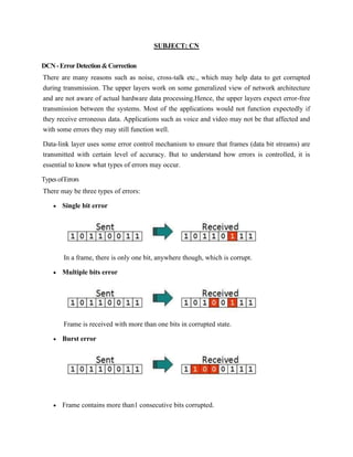
  • 1. SUBJECT: CN DCN-ErrorDetection&Correction There are many reasons such as noise, cross-talk etc., which may help data to get corrupted during transmission. The upper layers work on some generalized view of network architecture and are not aware of actual hardware data processing.Hence, the upper layers expect error-free transmission between the systems. Most of the applications would not function expectedly if they receive erroneous data. Applications such as voice and video may not be that affected and with some errors they may still function well. Data-link layer uses some error control mechanism to ensure that frames (data bit streams) are transmitted with certain level of accuracy. But to understand how errors is controlled, it is essential to know what types of errors may occur. TypesofErrors There may be three types of errors: • Single bit error In a frame, there is only one bit, anywhere though, which is corrupt. • Multiple bits error Frame is received with more than one bits in corrupted state. • Burst error • Frame contains more than1 consecutive bits corrupted.
  • 2. Error control mechanism may involve two possible ways: • Error detection • Error correction ErrorDetection Errors in the received frames are detected by means of Parity Check and Cyclic Redundancy Check (CRC). In both cases, few extra bits are sent along with actual data to confirm that bits received at other end are same as they were sent. If the counter-check at receiver’ end fails, the bits are considered corrupted. Parity Check One extra bit is sent along with the original bits to make number of 1s either even in case of even parity, or odd in case of odd parity. The sender while creating a frame counts the number of 1s in it. For example, if even parity is used and number of 1s is even then one bit with value 0 is added. This way number of 1s remains even.If the number of 1s is odd, to make it even a bit with value 1 is added. The receiver simply counts the number of 1s in a frame. If the count of 1s is even and even parity is used, the frame is considered to be not-corrupted and is accepted. If the count of 1s is odd and odd parity is used, the frame is still not corrupted. If a single bit flips in transit, the receiver can detect it by counting the number of 1s. But when more than one bits are erro neous, then it is very hard for the receiver to detect the error. Cyclic Redundancy Check (CRC) CRC is a different approach to detect if the received frame contains valid data. This technique involves binary division of the data bits being sent. The divisor is generated using polynomials. The sender performs a division operation on the bits being sent and calculates the remainder. Before sending the actual bits, the sender adds the remainder at the end of the actual bits. Actual data bits plus the remainder is called a codeword. The sender transmits data bits as codewords.
  • 3. At the other end, the receiver performs division operation on codewords using the same CRC divisor. If the remainder contains all zeros the data bits are accepted, otherwise it is considered as there some data corruption occurred in transit. ErrorCorrection In the digital world, error correction can be done in two ways: • Backward Error Correction When the receiver detects an error in the data received, it requests back the sender to retransmit the data unit. • Forward Error Correction When the receiver detects some error in the data received, it executes error-correcting code, which helps it to auto-recover and to correct some kinds of errors. The first one, Backward Error Correction, is simple and can only be efficiently used where retransmitting is not expensive. For example, fiber optics. But in case of wireless transmission retransmitting may cost too much. In the latter case, Forward Error Correction is used. To correct the error in data frame, the receiver must know exactly which bit in the frame is corrupted. To locate the bit in error, redundant bits are used as parity bits for error detection.For
  • 4. example, we take ASCII words (7 bits data), then there could be 8 kind of information we need: first seven bits to tell us which bit is error and one more bit to tell that there is no error. For m data bits, r redundant bits are used. r bits can provide 2r combinations of information. In m+r bit codeword, there is possibility that the r bits themselves may get corrupted. So the number of r bits used must inform about m+r bit locations plus no-error information, i.e. m+r+1. Multiple Access Protocol: The Data Link Layer is responsible for transmission of data between two nodes. Its main functions are- • Data Link Control • Multiple Access Control Data Link control – The data link control is responsible for reliable transmission of message over transmission channel by using techniques like framing, error control and flow control. For Data link control refer to – Stop and Wait ARQ
  • 5. Multiple Access Control – If there is a dedicated link between the sender and the receiver then data link control layer is sufficient, however if there is no dedicated link present then multiple stations can access the channel simultaneously. Hence multiple access protocols are required to decrease collision and avoid crosstalk. For example, in a classroom full of students, when a teacher asks a question and all the students (or stations) start answering simultaneously (send data at same time) then a lot of chaos is created( data overlap or data lost) then it is the job of the teacher (multiple access protocols) to manage the students and make them answer one at a time. Thus, protocols are required for sharing data on non dedicated channels. Multiple access protocols can be subdivided further as – ARP and RARP Difference Between ARP and RARP ARP and RARP both are the Network layer protocol. Whenever a host needs to send an IP datagram to another host, the sender requires both the logical address and physical address of the receiver. The dynamic mapping provides two protocols ARP and RARP. The basic difference between ARP and RARP is that ARP when provided with the logical address of the receiver it
  • 6. obtains the physical address of the receiver whereas in RARP when provided with the physical address of the host, it obtains the logical address of the host from the server. Comparison Chart BASIS FOR COMPARISON ARP RARP Full Form Address Resolution Protocol. Reverse Address Resolution Protocol. Basic Retrieves the physical address of the receiver. Retrieves the logical address for a computer from the server. Mapping ARP maps 32-bit logical (IP) address to 48-bit physical address. RARP maps 48-bit physical address to 32-bit logical (IP) address. Definition of ARP ARP (Address Resolution Protocol) is a network layer protocol. As ARP is a dynamic mapping protocol, each host in the network knows the Logical address of another host. Now, suppose a host needs to send the IP datagram to another host. But, the IP datagram must be encapsulated in a frame so that it can pass through the physical network between sender and receiver. Here, the sender needs the physical address of the receiver so that it is being identified that to which receiver the packet belong to when the packet travel in the physical network. For retrieving the physical address of the receiver the sender performs the following action. 1. The sender sends the ARP query packet on the network which is broadcasted to all the other host or router present in the network. 2. The ARP query packet contains the logical and physical address of the sender and the logical address of the receiver. 3. All the host and router receiving the ARP query packet process it but, only the intended receiver identifies its logical address present in the ARP query packet. 4. The receiver then sends ARP response packet which contains the logical (IP) address and physical address of the receiver. 5. The ARP response packet is unicast directly to the sender whose physical address is present in the ARP query packet.
  • 7. Definition of RARP RARP (Reverse Address Resolution Protocol) is also a network layer protocol. RARP is a TCP/IP protocol that allows any host to obtain its IP address from the server. RARP is adapted from the ARP protocol and it is just reverse of ARP. RARP perform following steps to obtain an IP address from the server. 1. The sender broadcast the RARP request to all the other host present in the network. 2. The RARP request packet contains the physical address of the sender. 3. All the host receiving the RARP request packet process it but, the authorized host only which can serve RARP service, responds to the RARP request packet such host are known as RARP Server. 4. The authorized RARP server replies directly to requesting host with the RARP response packet which contains IP address for the sender.
  • 8. RARP is outdated now because of two reasons. First, the RARP is using the broadcast service of the data-link layer; that means the RARP must be present at each network. Second, RARP only provides IP address but today the computer also need other information. Point-to-Point Protocol (PPP) Point-to-point protocol (PPP) is a computer network protocol used to transfer a datagram between two directly connected (point-to-point) computers. This protocol is used for a very basic level of connectivity providing data linkage between the computers. Point-to-point protocol is widely used for the heavier and faster connections necessary for broadband communications. Point-to-point protocol is also known as RFC 1661. There are many physical mediums for point-to-point connectivity, such as simple serial cables, mobile phones and telephone lines. For Ethernet networks, TCP and IP were introduced for data communication purposes. Both of these protocols have specifications for Ethernet networks only. Thus, TCP and IP do not support point-to-point connections. Therefore, PPP was introduced for point-to-point connectivity without Ethernet. When two computers are being connected directly, both ends send a request for configuration. Once the computers are connected, PPP handles link control, data control and protocol encapsulation. IEEE 802.3
  • 9. IEEE 802.3 is a set of standards put forth by the Institute of Electrical and Electronics Engineers (IEEE) that define Ethernet-based networks as well as the name of the working group assigned to develop these standards. IEEE 802.3 is otherwise known as the Ethernet standard and defines the physical layer and the media access control (MAC) of the data link layer for wired Ethernet networks, generally as a local area network (LAN) technology. IEEE 802.3 specifies the physical and networking characteristics of an Ethernet network, like how physical connections between nodes (routers/switches/hubs) are made through various wired media like copper coaxial or fiber cable. The technology was developed to work with the IEEE 802.1 standard for network architecture and its first released standard was Ethernet II in 1982, which featured 10 Mbit/s over thick coax cable and featured frames with a "Type" field. In 1983 the first standard with the name IEEE 802.3 for 10BASE5 (thick Ethernet or thicknet) was developed. It had the same speed as the previous Ethernet II standard, but the "Type" field was replaced by a "Length" field. 802.3a followed in 1985 and was designated as 10BASE2, which was essentially the same as 10BASE5 but ran on thinner coax cables, therefore it was also known as thinnet or cheapnet. There are a multitude of additions and revisions to the 802.3 standard and each is designated with letters concatenated after the number "3". Other notable standards are 802.3i for 10Base-T for using twister pair wire and 802.3j 10BASE-F for using fiber-optic cables. 802.5 A token ring network is a local area network (LAN) topology where nodes/stations are arranged in a ring topology. Data passes sequentially between nodes on the network until it returns to the source station. To prevent congestion and collision, a token ring topology uses a token to ensure that only one node/station on the line is used at a time, thereby easily denoting media users of its activity. A token ring LAN is physically wired as a star topology but configured as a ring topology. The token ring LAN system was standardized by the Institute of Electrical and Electronics Engineers as IEEE 802.5. Initially, the token ring LAN highlighted, debated advantages over the Ethernet. During the 1990s, token-ring LAN pricing and usage gradually declined as switched Ethernet and faster variants hit the market. In the mid-1980s, token ring LAN speeds were standardized between 4 and 16 Mbps. The token ring LAN process is delineated by the following sequence of events: • A token continually circulates inside the toke ring LAN • To transmit a message, a node inserts a message and destination address inside an empty token. • The token is examined by each successive node.
  • 10. • The destination node copies the message data and returns the token to the source with the source address and a data receipt message. • The source receives the returned token, verifies copied and received data and empties the token. • The empty token now changes to circulation mode, and the process continues. FDDI (Fiber Distributed Data Interface) Fiber distributed data interface (FDDI), which is an optical data communication standard used for long distance networks provides communication with fiber optic lines up to 200 kilometers at a speed of 100 megabit per second (Mbps). FDDI has dual primary and secondary communication rings. The primary ring works alongside the network, and the secondary ring remains idle and available for backup. FDDI was later extended to FDDI-2 for long distance voice and multimedia communication. Organizations use this medium for voice and video conferences, online lectures, news and other multimedia. FDDI networks, which are designed for geographically large-scaled organizations that support thousands of end users, operates in the OSI model's physical and media access control (MAC layers). The American National Standards Committee (ANSC) formally standardized FDDI as the best linking medium for local area networks (LAN), which use FDDI for long-distance communication. FDDI also is used by single and multi-mode fiber optic, which have different communication mechanisms. Multi-mode fiber optic uses a lead generation device, whereas single-mode fiber optic uses laser for data transmission only. 802.6 A metropolitan area network (MAN) is similar to a local area network (LAN) but spans an entire city or campus. MANs are formed by connecting multiple LANs. Thus, MANs are larger than LANs but smaller than wide area networks (WAN). MANs are extremely efficient and provide fast communication via high-speed carriers, such as fiber optic cables. A MAN is ideal for many kinds of network users because it is a medium-size network. MANs are used to build networks with high data connection speeds for cities and towns. The working mechanism of a MAN is similar to an Internet Service Provider (ISP), but a MAN is not owned by a single organization. Like a WAN, a MAN provides shared network connections to its users. A MAN mostly works on the data link layer, which is Layer 2 of the Open Systems Interconnection (OSI) model. Distributed Queue Dual Bus (DQDB) is the MAN
  • 11. standard specified by the Institute Of Electrical And Electronics Engineers (IEEE) as IEEE 802.6. Using this standard, a MAN extends up to 30-40 km, or 20-25 miles. Physical Layer, Types of media wired and wireless media In data communication terminology, a transmission medium is a physical path between the transmitter and the receiver i.e it is the channel through which data is sent from one place to another. Transmission Media is broadly classified into the following type 1.GuidedMedia: It is also referred to as Wired or Bounded transmission media. Signals being transmitted are directed and confined in a narrow pathway by using physical links. Features: • High Speed • Secure • Used for comparatively shorter distances There are 3 major types of Guided Media: (i) Twisted Pair Cable – It consists of 2 separately insulated conductor wires wound about each other. Generally, several such pairs are bundled together in a protective sheath. They are the most widely used Transmission Media. Twisted Pair is of two types: Unshielded Twisted Pair (UTP): This type of cable has the ability to block interference and does not depend on a physical shield for this purpose. It is used for telephonic applications. 1. Advantages: • Least expensive
  • 12. • Easy to install • High speed capacity Disadvantages: • Susceptible to external interference • Lower capacity and performance in comparison to STP • Short distance transmission due to attenuation 2. Shielded Twisted Pair (STP): This type of cable consists of a special jacket to block external interference. It is used in fast-data-rate Ethernet and in voice and data channels of telephone lines. Advantages: • Better performance at a higher data rate in comparison to UTP • Eliminates crosstalk • Comparitively faster Disadvantages: • Comparitively difficult to install and manufacture • More expensive Bulky (ii) Coaxial Cable – It has an outer plastic covering containing 2 parallel conductors each having a separate insulated protection cover. Coaxial cable transmits information in two modes: Baseband mode(dedicated cable bandwidth) and Broadband mode(cable bandwidth is split into separate ranges). Cable TVs and analog television networks widely use Coaxial cables. Advantages: • High Bandwidth • Better noise Immunity • Easy to install and expand • Inexpensive Disadvantages: • Single cable failure can disrupt the entire network (iii) Optical Fibre Cable – It uses the concept of reflection of light through a core made up of glass or plastic. The core is surrounded by a less dense glass or plastic covering called the cladding. It is used for transmission of large volumes of data. Advantages: • Increased capacity and bandwidth • Light weight • Less signal attenuation Disadvantages: • Difficult to install and maintain • High cost • Fragile 2. Unguided Media: It is also referred to as Wireless or Unbounded transmission media.No physical medium is required for the transmission of electromagnetic signals.
  • 13. Features: • Signal is broadcasted through air • Less Secure • Used for larger distances There are 3 major types of Unguided Media: (i) Radiowaves – These are easy to generate and can penetrate through buildings.The sending and receiving antennas need not be aligned. Frequency Range:3KHz – 1GHz. AM and FM radios and cordless phones use Radiowaves for transmission. Further Categorized as: (i) Terrestrial and (ii) Satellite. (ii) Microwaves – It is a line of sight transmission i.e. the sending and receiving antennas need to be properly aligned with each other. The distance covered by the signal is directly proportional to the height of the antenna. Frequency Range:1GHz – 300GHz. These are majorly used for mobile phone communication and television distribution. (iii) Infrared – Infrared waves are used for very short distance communication. They cannot penetrate through obstacles. This prevents interference between systems. Frequency Range:300GHz – 400THz. It is used in TV remotes, wireless mouse, keyboard, printer, etc. Unicast Routing Protocols: RIP, OSPF, and BGP Introduction The metric assigned to each network depends on the type of protocol RIP (Routing Information Protocol) Treat each network as equal The cost of passing through each network is the same: one hop count Open Shortest Path First (OSPF) Allow administrator to assign a cost for passing through a network based on the type of serviced required For example, maximum throughput or minimum delay Border Gateway Protocol (BGP) The criterion is the policy, which can be set by the administrator Intra & Inter Domain Routing Routing inside an autonomous system is referred to as intra domain routing. Routing between autonomous systems is referred to as inter domain routing. Intradomain Routing Routing inside an autonomous system Each AS can chose its own intradomain routing protocol Examples: distance vector and link state Interdomain Routing Routing between autonomous systems
  • 14. Only one interdomain routing protocol is usually used between ASs Examples: path vector RIP Routing Information Protocol (RIP) is a dynamic protocol used to find the best route or path from end-to-end (source to destination) over a network by using a routing metric/hop count algorithm. This algorithm is used to determine the shortest path from the source to destination, which allows the data to be delivered at high speed in the shortest time. RIP plays an important role providing the shortest and best path for data to take from node to node. The hop is the step towards the next existing device, which could be a router, computer or other device. Once the length of the hop is determined, the information is stored in a routing table for future use. RIP is being used in both local and wide area networks and is generally considered to be easily configured and implemented. OSPF Open Shortest Path First (OSPF) is a link state routing protocol (LSRP) that uses the Shortest Path First (SPF) network communication algorithm (Dijkstra's algorithm) to calculate the shortest connection path between known devices. OSPF bis an Interior Gateway Protocol (IGP) that routes Internet Protocol (IP) packets within a single routing network domain only. OSPF finds the best network layout (topology) by calculating shortest device connection paths using the Shortest Path First (SPF) algorithm.
  • 15. For example, a person in city A wants to travel to city M and is given two options: • Travel via cities B and C. The route would be ABCM. And the distance (or bandwidth cost in the networking case) for A-B is 10 miles, B-C is 5 miles and C-M is 10 miles. • Travel via city F. The route would be AFM. And the distance for A-F is 20 miles and F- M is 10 miles. The shortest route is always the one with least amount of distance covered in total. Thus, the ABCM route is the better option (10+5+10=25), even though the person has to travel to two cities as the associated total cost to travel to the destination is less than the second option with a single city (20+10=30). OSPF performs a similar algorithm by first calculating the shortest path between the source and destination based on link bandwidth cost and then allows the network to send and receive IP packets via the shortest route. BGP Border Gateway Protocol (BGP) is a routing protocol used to transfer data and information between different host gateways, the Internet or autonomous systems. BGP is a Path Vector Protocol (PVP), which maintains paths to different hosts, networks and gateway routers and determines the routing decision based on that. It does not use Interior Gateway Protocol (IGP) metrics for routing decisions, but only decides the route based on path, network policies and rule sets. Sometimes, BGP is described as a reachability protocol rather than a routing protocol. BGP roles include: • Because it is a PVP, BGP communicates the entire autonomous system/network path topology to other networks • Maintains its routing table with topologies of all externally connected networks • Supports classless interdomain routing (CIDR), which allocates Internet Protocol (IP) addresses to connected Internet devices When used to facilitate communication between different autonomous systems, BGP is referred to as External BGP (EBGP). When used at host networks/autonomous systems, BGP is referred to as Internal BGP (IBGP). BGP was created to extend and replace Exterior Gateway Protocol (EGP). MOSPF This isn't really a category, but a specific instance of a protocol. MOSPF is the multicast extension to OSPF (Open Shortest Path First) which is a unicast link-state routing protocol.
  • 16. Link-state routing protocols work by having each router send a routing message periodically listing its neighbours and how far away they are. These routing messages are flooded throughout the entire network, and so every router can build up a map of the network which it can then use to build forwarding tables (using a Dijkstra algorithm) to decide quickly which is the correct next hop for send a particular packet. Extending this to multicast is achieved simply by having each router also list in a routing message the groups for which it has local receivers. Thus given the map and the locations of the receivers, a router can also build a multicast forwarding table for each group. MOSPF also suffers from poor scaling. With flood-and-prune protocols, data traffic is an implicit message about where there are senders, and so routers need to store unwanted state where there are no receivers. With MOSPF there are explicit messages about where all the receivers are, and so routers need to store unwanted state where there are no senders. However, both types of protocol build very efficient distribution trees. Distance Vector Multicast Routing Protocol (DVMRP) Distance Vector Multicast Routing Protocol (DVMRP) is an efficient Interior Gateway Protocol routing mechanism that combines Routing Information Protocol features with a truncated reverse path broadcasting algorithm for IP multitask data sharing between connectionless autonomous systems. DVRMP's main tasks include: • Tracks multicast datagram source paths • Encapsulates packets as Internet Protocol (IP) datagrams • Supports multicast IP datagram tunneling via unsupported encapsulated and addressed unicast packet routers • Generates dynamic multicast IP delivery trees via reverse path multicasting and a distributed routing algorithm • Exchanges routing datagrams made up of small, fixed-length headers and tagged data streams via Internet Group Management Protocol • Handles tunnel and physical interfacing according to broadcast routing exchange source trees produced during truncated tree branch removal • Manages reverse path forwarding for multicast traffic forwarding to downstream interfaces DVMRP header components are as follows: • Version • Type • Subtype: Response, request, non-membership report or non-membership cancellations • Checksum: Complete message sum of 16-bit ones, not including IP headers. Requires 16- bit alignment. Checksum computation field is zero.