
Recommended
More Related Content
What's hot
What's hot (20)
Viewers also liked
Viewers also liked (19)
Similar to Data Link Layer
Similar to Data Link Layer (20)
More from Mukesh Tekwani
More from Mukesh Tekwani (20)
Recently uploaded
Recently uploaded (20)
Data Link Layer
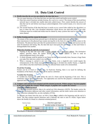
- 1. mukeshtekwani@hotmail.com Prof. Mukesh N. Tekwani 1Chap 11. Data Link Control 11. Data Link Control 1. Briefly describe the services provided by the data link layer. The two main functions of the data link layer are data link control and media access control. (1) Data link control functions include framing, flow and error control. The stream of bits received from network layer is divided into smaller data units called frames. Flow control decides the amount of data that can be sent before receiving an acknowledgment. Error control means error detection and correction. (2) The second function of the data link layer is media access control (also called as line discipline), or how to share the link. Line discipline determines which device can send and when it can send. Collisions must be avoided and media must be shared by many systems that need to transmit on the same channel. 2. Define framing and the reason for its need. The stream of bits received from network layer is divided into smaller data units called frames. Data transmission in the physical layer means moving bits in the form of a signal from the source to the destination. The physical layer provides bit synchronization to ensure that the sender and receiver use the same bit durations and timing. But, the data link layer must pack bits into frames, so that each frame is distinguishable from another. What does framing do and why is it necessary? 1. Framing in the data link layer adds a sender address and a destination address. The destination address specifies where the packet should go; the sender address is used to send an acknowledgement back to the sender. 2. A whole message could be packed in one frame but that is not normally done, because a large frame can make flow and error control very inefficient. 3. When a message is carried in one very large frame, even a single-bit error would require the retransmission of the whole message. When a message is divided into smaller frames, a single-bit error affects only that small frame and only the affected frame needs to be retransmitted. Fixed-Size Framing Frames can be of fixed or variable size. In fixed-size framing, there is no need for defining the boundaries of the frames; the size itself can be used as a delimiter. Variable-Size Framing In variable-size framing, we must define the end of a frame and the beginning of the next. This is commonly used in local area networks. Two approaches are used for this purpose: a character-oriented approach and a bit-oriented approach. 3. Compare and contrast byte-oriented and bit-oriented protocols. Which category has been popular in the past (explain the reason)? Which category is popular now (explain the reason)? Character-oriented protocol In a character-oriented protocol, data to be carried are 8-bit characters (ASCII). The header carries the source and destination addresses and other control information, and the trailer carries error detection or error correction redundant bits, are also multiples of 8 bits. To separate one frame from the next, an 8-bit (1-byte) flag is added at the beginning and the end of a frame. The flag contains special characters and it indicates the start or end of a frame. Figure below shows the format of a frame in a character-oriented protocol. Drawbacks of character-oriented protocol: End of a frame Start of a frame
- 2. Prof. Mukesh N Tekwani mukeshtekwani@hotmail.com 2 Data Link Control Character-oriented framing was popular when only text was exchanged by the data link layers. The flag could be selected to be any character not used for text communication. But now we send other types of information such as graphs, audio, and video. Any pattern used for the flag could also be part of the information. If this happens, the receiver, when it encounters this pattern in the middle of the data, thinks it has reached the end of the frame. This drawback is overcome by using a byte-stuffing strategy. Bit-oriented protocol In a bit-oriented protocol, the data section of a frame is a sequence of bits which is interpreted by the upper layer as text, audio, video or graphics. To separate one frame from another, an 8-bit flag such as 01111110 is used and it marks the beginning and end of a frame. This is shown in the diagram below: Drawbacks: This flag can create the same type of problem as in the byte-oriented protocols. That is, if the flag pattern appears in the data, we need to somehow inform the receiver that this is not the end of the frame. We do this by stuffing 1 single bit (instead of 1 byte) to prevent the pattern from looking like a flag. The strategy is called bit stuffing. In bit stuffing, if a 0 and five consecutive I bits are encountered, an extra 0 is added. This extra stuffed bit is eventually removed from the data by the receiver. Note that the extra bit is added after one 0 followed by five 1s regardless of the value of the next bit. This guarantees that the flag field sequence does not inadvertently appear in the frame. 4. Compare and contrast byte-stuffing and bit-stuffing. Byte-stuffing Strategy: Byte stuffing is the process of adding 1 extra byte whenever there is a flag or escape character in the text. 1. In byte stuffing, a special byte is added to the data section of the frame when there is a character with the same pattern as the flag. The data section is stuffed with an extra byte. This byte is usually called the escape character (ESC), which has a predefined bit pattern. 2. Whenever the receiver encounters the ESC character, it removes it from the data section and treats the next character as data, not a delimiting flag. 3. Byte stuffing by the escape character allows the presence of the flag in the data section of the frame, but it creates another problem. What happens if the text contains one or more escape characters followed by a flag? The receiver removes the escape character, but keeps the flag, which is incorrectly interpreted as the end of the frame. 4. To solve this problem, the escape characters that are part of the text must also be marked by another escape character. In other words, if the escape character is part of the text, an extra one is added to show that the second one is part of the text. Bit-stuffing Strategy: 1. In a bit-oriented protocol, the data section of a frame is a sequence of bits which is interpreted by the upper layer as text, audio, video or graphics. 2. To separate one frame from another, an 8-bit flag such as 01111110 is used and it marks the beginning and end of a frame. 3. Bit stuffing is the process of adding one extra 0 whenever five consecutive 1s follow a 0 in the data, so that the receiver does not mistake the pattern 0111110 for a flag. 4. This flag can create some problems. If the flag pattern appears in the data, we need to somehow inform the receiver that this is not the end of the frame. 5. We do this by stuffing 1 single bit (instead of I byte) to prevent the pattern from looking like a flag. The strategy is called bit stuffing. 6. In bit stuffing, if a 0 and five consecutive 1 bits are encountered, an extra 0 is added. This extra
- 3. mukeshtekwani@hotmail.com Prof. Mukesh N. Tekwani 3Chap 11: Data Link Control stuffed bit is eventually removed from the data by the receiver. The extra bit is added after one 0 followed by five 1s regardless of the value of the next bit. This guarantees that the flag field sequence does not appear in the frame by mistake. Even if we have a 0 after five 1s, we still stuff a 0. The 0 will be removed by the receiver. This means that if the flaglike pattern 01111110 appears in the data, it will change to 011111010 (stuffed). 5. Compare and contrast flow control and error control Flow Control: 1. Flow control refers to a set of procedures used to restrict the amount of data that the sender can send before waiting for acknowledgment. 2. Flow control is concerned with the amount of data that can be sent before receiving an acknowledgment. 3. Any receiving device has a limited speed at which it can process incoming data and a limited amount of memory in which to store incoming data. The receiving device should not receive data at a rate that is more than the rate at which it can process this data 4. The receiving device must be able to inform the sending device before those limits are reached and to request that the transmitting device send fewer frames or stop temporarily. 5. Incoming data must be checked and processed before they can be used. The rate of such processing is often slower than the rate of transmission. For this reason, each receiving device has a block of memory, called a buffer, reserved for storing incoming data until they are processed. If the buffer begins to fill up, the receiver must be able to tell the sender to halt transmission until it is once again able to receive. Error Control: 1. Error control in the data link layer is based on automatic repeat request, which is the retransmission of data. 2. Error control involves both error detection and error correction. 3. It allows the receiver to inform the sender of any frames lost or damaged in transmission and coordinates the retransmission of those frames by the sender. 4. In the data link layer, the term error control refers primarily to methods of error detection and retransmission. 5. How is error control implemented in the data link layer? Error control in the data link layer is implemented simply: Any time an error is detected in an exchange, specified frames are retransmitted. This process is called automatic repeat request (ARQ). 6. What are the two protocols for noiseless channels? What are the three protocols for noisy channels? Data link layer uses protocols to combine framing, flow control, and error control. The protocols used by this layer can be divided into two types: a) Protocols for noiseless channel
- 4. Prof. Mukesh N Tekwani mukeshtekwani@hotmail.com 4 Data Link Control a. Simplest b. Stop-and-wait b) Protocols for noisy channel a. Stop-and-Wait ARQ b. Go-Back-N ARQ c. Selective Repeat ARQ 7. Describe the Simplest protocol used for an ideal (noiseless) channel. Simplest Protocol: 1. The Simplest Protocol has no flow or error control. 2. It is a unidirectional protocol in which data frames are traveling in only one direction-from the sender to receiver. 3. We assume that the receiver can immediately handle any frame it receives with a processing time that is small enough to be negligible. 4. The data link layer at the sender site gets data from its network layer, makes a frame out of the data, and sends it. 5. The data link layer at the receiver site receives a frame from its physical layer, removes header from the frame (extracts data from the frame) and delivers the data to its network layer. 6. Thus, the receiver can never be overwhelmed (flooded) with incoming frames. 7. The data link layers of the sender and receiver provide transmission services for their network layers. The data link layers use the services provided by their physical layers for the physical transmission of bits. Implementation of the protocol as a procedure: We introduce the idea of events in this protocol. The procedure at the sender site is constantly running; an action takes place only when there is a request from the network layer. The procedure at the receiver site is also constantly running, but there is an action only when the physical layer informs it. Both procedures are constantly running because they do not know when the corresponding events will occur. Sender-side Algorithm: Receiver-side Algorithm: while (true) //repeat forever { WaitForEvent(); //sleep until an event occurs If(Event(RequestToSend)) //there is a //packet to send { GetData(); MakeFrame(); SendFrame(); //send the frame } } while (true) //repeat forever { WaitForEvent(); //sleep until an event occurs If(Event(ArrivalNotofication)) //there is a //packet to send { ReceiveFrame(); ExtractData(); DeliverData(); //send the frame } }
- 5. mukeshtekwani@hotmail.com Prof. Mukesh N. Tekwani 5Chap 11: Data Link Control 8. Describe the Stop-And-Wait Protocol for a noiseless channel. 1. The Stop-and-Wait Protocol is so called because the sender sends one frame, stops until it receives confirmation from the receiver (okay to go ahead), and then sends the next frame. 2. If data frames arrive at the receiver site faster than they can be processed, the frames must be stored until their use. 3. Normally, the receiver does not have enough storage space, especially if it is receiving data from many sources. This may result in either the discarding of frames or denial of service. 4. To prevent the receiver from becoming flooded with frames, we must tell the sender to slow down. 5. There must be feedback from the receiver to the sender. 6. We have unidirectional communication for data frames, but auxiliary ACK frames (acknowledgment) travel from the other direction. We add flow control to the Simplest protocol. We use a half-duplex link.
- 6. Prof. Mukesh N Tekwani mukeshtekwani@hotmail.com 6 Data Link Control Sender-side Algorithm for Stop-And-Wait Protocol: Receiver-side Algorithm for Stop-And-Wait Protocol: 9. Discuss the Stop-And-Wait Automatic Repeat Request Protocol for a noisy channel. 1. The Stop-and-Wait Automatic Repeat Request (Stop-and-Wait ARQ) is a modification of the Stop-and-Wait protocol. It adds a simple error control mechanism to the Stop-and-Wait Protocol. 2. Redundancy Bits in frame: To detect and correct corrupted frames, we need to add redundancy bits to our data frame. When the frame arrives at the receiver site, it is checked and if it is corrupted, it is discarded. 3. Error detection by not responding: No response from the receiver implies that it has detected some errors. 4. Frame numbering: Lost frames are more difficult to handle than corrupted ones. In other protocols such as Simplest and Stop-and-Wait, there was no way to identify a frame. The received frame could be the correct one, or a duplicate, or a frame out of order. We now number the frames. When the receiver receives a data frame that is out of order, this means that frames were either lost or duplicated. 5. The corrupted and lost frames must be resent in this protocol. If the receiver does not respond when there is an error, how can the sender know which frame to resend? To solve this problem, the sender keeps a copy of the sent frame. At the same time, it starts a timer. If the timer expires and there is no ACK for the sent frame, the frame is resent, the copy is held, and the timer is restarted. Since the protocol uses the stop-and-wait mechanism, there is only one specific frame that needs an ACK even though several copies of the same frame can be in the network. 6. Numbering the ACK frames: Since an ACK frame can also be corrupted and lost, it also needs redundancy
- 7. mukeshtekwani@hotmail.com Prof. Mukesh N. Tekwani 7Chap 11: Data Link Control bits and a sequence number. The ACK frame for this protocol has a sequence number field. The sender discards a corrupted ACK frame. 7. Sequence Numbers: We want to minimize the frame size and therefore we look for the smallest range of sequence numbers for numbering the frames. If the sequence number field is m bits long, the sequence number can go from 0 to 2m – 1, and then wrap around. If we have used x as a sequence number then the next frame will have x + 1 as the sequence number. 8. Acknowledgement Number: The acknowledgment numbers always announce the sequence number of the next frame expected by the receiver. For example, if frame 0 has arrived safe and sound, the receiver sends an ACK frame with acknowledgment 1 (meaning frame 1 is expected next). If frame 1 has arrived safe and sound, the receiver sends an ACK frame with acknowledgment 0 (meaning frame 0 is expected). 9. Inefficient: This protocol is very inefficient if the channel has a large bandwidth (thick) and if the round-trip delay is long. The product of these two parameters is called bandwidth-delay product. 10. Pipelining: Pipelining means beginning a task before the previous task has ended. In this protocol there is no pipelining because we have to wait for a frame to reach the destination, and receive the acknowledgment before the next frame is sent. Protocol Design Issues: 1. The sending device keeps a copy of the last frame sent until it receives an ACK for that frame. It can retransmit the lost or damaged frames . 2. The Sender has a control variable Sn which is the sequence number of the next frame to send. 3. Similarly, the Receiver has a control variable Rn which holds the sequence number of the next frame that is expected. 4. When a frame is sent, the value of Sn is incremented (modulo – 2), (if it is 1 it becomes 0, and vice- versa. 5. When a frame is received, the value of Rn is incremented (modulo – 2), (if it is 1 it becomes 0, etc) 6. A data frame 0 is acknowledged by ACK 1 frame indicating that the receiver has got the frame 0 and is now expecting data frame 0. Sender-side Algorithm: Sn = 0; //frame 0 should be sent first canSend = true; while(true) { WaitforEvent(); //sleep until an event occurs if (Event (RequestToSend) AND canSend) { GetData () ;
- 8. Prof. Mukesh N Tekwani mukeshtekwani@hotmail.com 8 Data Link Control MakeFrame (Sn) ; StoreFrame(Sn); SendFrame(Sn) ; StartTimerO; Sn = Sn + 1; canSend = false; } WaitforEvent(); if (Event (ArrivaINotification) { ReceiveFrame(ackNo); if(not corrupted AND ackNo == Sn) //valid ACK { Stoptimer(); PurgeFrame(Sn-l); //copy is not needed canSend = true; } } if (Event (TimeOot) { StartTimer(); ResendFrame(Sn-l); } } Receiver Side Algorithm: Rn = 0; //frame 0 expected to arrive first while (true) { WaitForEvent(); //sleep until an event occurs if(Event(Arriva1Notification)) //data frame arrices { ReceiveFrame(); if(corrupted(frame)) sleep (); if (seqNo == Rn) //valid data frame { ExtractData(); De1iverData(); //deliver data Rn = Rn + 1; } SendFrame (Rn) ; //send an ACK } } 10. Assume that, in a Stop-and-Wait ARQ system, the bandwidth of the line is 1 Mbps, and 1 bit takes 20 ms to make a round trip. a) What is the bandwidth-delay product? b)If the system data frames are 1000 bits in length, what is the utilization percentage of the link? c) If the protocol can send 15 frames before stopping and waiting for the ACK, what is the utilization? a) The bandwidth-delay product is : (1 x 106 Mbps) x (20 x 10-3 s) = 20,000 bits b) The system can send 20,000 bits during the time it takes for the data to go from the sender to the receiver and then back again. But, the system sends only 1000 bits. Thus, the link utilization is only 1000/20,000, or 5 percent. For this reason, for a link with a high bandwidth or long delay, the use of Stop-and-Wait ARQ wastes the capacity of the link. c) The system can send 15 frames = 15 x 1000 bits = 15,000 bits. The utilization now becomes 15000/20000 = 75%.
- 9. mukeshtekwani@hotmail.com Prof. Mukesh N. Tekwani 9Chap 11: Data Link Control