Presiding Officer Training module 2024 lok sabha elections
CN R16 -UNIT-3.pdf
1. UNIT-3
Data Link Layer: - The Data Link Layer - Services Provided to the Network Layer – Framing – Error
Control – Flow Control, Error Detection and Correction – Error-Correcting Codes – Error Detecting Codes,
Elementary Data Link Protocols- A Utopian Simplex Protocol-A Simplex Stop and Wait Protocol for an
Error free channel-A Simplex Stop and Wait Protocol for a Noisy Channel, Sliding Window Protocols-A
One Bit Sliding Window Protocol-A Protocol Using Go-Back-NA Protocol Using Selective Repeat
DATA LINK LAYER DESIGN ISSUES
DATA LINK LAYER
The data link layer has a number of specific functions it can carry out. These functions include
1. Providing a well-defined service interface to the network layer.
2. Provides services for the reliable interchange of data across a data link established by the
physical layer.
3. Link layer protocols manage the establishment, maintenance, and release of data-link
connections.
4. Data-link protocols control the flow of data, dealing with transmission errors, and
supervise data error recovery.
5. Regulating the flow of data so that slow receivers are not swamped by fast senders.
6. Recovery from abnormal conditions.
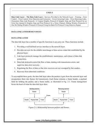
To accomplish these goals, the data link layer takes the packets it gets from the network layer and
encapsulates them into frames for transmission. Each frame contains a frame header, a payload
field for holding the packet, and a frame trailer, as illustrated in Fig. 2-1. Frame management
forms the heart of what the data link layer does.
Figure 2-1. Relationship between packets and frames.
1
www.Jntufastupdates.com
2. Data Link Layer Design Issues
1. Providing a well-defined service interface to the network layer
2. Determining how the bits of the physical layer are grouped into frames
3. Dealing with transmission errors
4. Regulating the flow of frames so that slow receivers are not swamped by fast senders.
1. Services Provided to the Network Layer
The function of the data link layer is to provide service to the network layer.
The principal service is transferring data from the network layer on the source machine to
thenetwork layer on the destination machine.
The network layer hands some bits to the data link layer for transmission to the destination, the
jobof the data link layer is to transmit the bits to the destination machine, so they can be handed
over to the network layer on the destination machine.
The job of the data link layer is to
transmit the bits to the destination
machine so they can be handed over
to the network layer there, as shown
in Fig.(a). The actual transmission
follows the path of Fig.(b), but it is
easier to think in terms of two data
link layer processes communicating
using a data link protocol.
The data link layer can be designed to offer various services, Three possibilities that are commonly
provided are:
1. Unacknowledged connectionless service.
2. Acknowledged connectionless service.
3. Acknowledged connection-oriented service.
Unacknowledged connectionless service
Unacknowledged connectionless service consists of having the source machine send independent frames to
the destination machine without having the destination machine acknowledge them. No connection is
established beforehand or released afterward. Good channels with low eror rates, for real-time traffic, such
as speech.
Acknowledged connectionless service
When this service is offered, there are still no connections used, but each frame sent is individually
acknowledged. This way, the sender knows whether or not a frame has arrived safely. Good for unreliable
channels, such as wireless.
Acknowledged connection-oriented service
2
www.Jntufastupdates.com
3. With this service, the source and destination machines establish a connection before any data are
transferred. Each frame sent over the connection is numbered, and the data link layer guarantees that each
frame sent is received. Furthermore, it guarantees that each frame is received exactly once and that all
frames are received in the right order.
When connection-oriented service is used, transfers have three distinct phases.
1. In the first phase the connection is established by having both sides initialize variable and counter
need to keep track of which frames have been received and which ones have not.
2. In the second phase, one or more frames are actually transmitted.
3. In the third phase, the connection is released, freeing up the variables, buffers, and other resources
used to maintain the connection.
2. Framing
In order to provide service to the network layer, the data link layer must use the service provided
toit by the physical layer.
What the physical layer does is accept raw bit stream and attempt to deliver it to the
destination.This bit stream is not guaranteed to be error free.
It is up to the data link layer to detect, and if necessary, correct errors.
The usual approach is for the data link layer to break the bit stream up into discrete frames
andcompute the checksum for each frame. When the frames arrive at the destination , the
checksum is re-computed.
There are four methods of breaking up the bit stream
1. Character count.
2. Starting and ending character stuffing.
3. Starting and ending flags, with bit stuffing.
4. Physical layer coding violations.
Character count, uses a field in the header to specify the number of characters in the frame. When the data
link layer at the destination sees the character count, it knows how many characters follow. Problem: count
can possible be misrepresented by a transmission error. This method is rarely used anymore.
Starting and ending character stuffing, gets around the problem of resynchronization after an error by
having each frame start with the ASCII character sequence DLE STX and end with the sequence DLE
ETX. (DLE is Data Link Escape, STX is Start of Text, and ETX is End of Text). Problem: a serious
problem occurs with this method when binary data, such as object programs or floating-point numbers, are
being transmitted it is possible that the DLE, STX, and ETX characters can occur, which will interfere with
the framing. One way to solve this problem is to have the sender's data link layer insert and DLE character
just before each "accidental" DLE and the data link layer on the other machine removes them before it
gives the data to the network layer, this is called Character stuffing.
Starting and ending flags with bit stuffing, allows data frames to contain and arbitrary number of bits
and allows character codes with an arbitrary number of bits per character. Each frame begins and ends with
a special bit pattern, 01111110, called a flag byte. Whenever the sender's data link layer encounters five
3
www.Jntufastupdates.com
4. consecutive ones in the data, it automatically stuffs a 0 bit into the outgoing bit stream, which is called bit
stuffing. The receiving machine destuffs the 0 bit. • The fourth method, Physical coding violations, is only
applicable to networks in which the encoding on the physical medium contains some redundancy. For
example, some LANs encode 1 bit of data by using 2 physical bits.
3. Error Control
The next problem to deal with is to make sure all frames are eventually delivered to the network
layer at the destination, and in proper order.
The usual way to ensure reliable delivery is to provide the sender with some feedback about what is
happening at the other end of the line.
One complication with this is that the frame may vanish completely, in which case, the receiver
will not react at all, since it has no reason to react.
This possibility is dealt with by introducing timers into the data link layer. When the sender
transmits a frame, it generally also starts a timer. The timer is set to go off after an interval long
enough for the frame to reach the destination machine. If the frame or acknowledgment is lost the
timer will go off. The obvious solution is to transmit the frame again. This creates the problem of
possible sending frames multiple times. To prevent this from happening, it is generally necessary to
assign sequence numbers to outgoing frames, so that the receiver can distinguish retransmission
from originals.
The whole issue of managing the timers and sequence numbers so as to ensure that each frame is
ultimately passed to the network layer at the destination exactly one, no more no less, is an
important part of the data link layer's duties.
4. Flow Control
Another important design issue that occurs in the data link layer (and higher layers as well) is what
to do with a sender that systematically wants to transmit frames faster than a receiver can accept
them.
This situation can easily occur when the sender is running on a fast computer and the receiver is
running on a slow machine.
The usual solution is to introduce flow control to throttle the sender into sending no faster than the
receiver can handle the traffic.
Various flow control schemes are known, but most of them use the same basic principle, eg HDLC.
The protocol contains well-defined rules about when a sender may transmit the next frame.
ERROR DETECTION AND CORRECTION
Error sources are present when data is transmitted over a medium. Even if all possible error-reducing
measures are used during the transmission, an error invariably creeps in and begins to disrupt data
transmission. Any computer or communication network must deliver accurate messages.
Error detection is applied mostly in the data-link layer but is also performed in other layers. In some cases,
the transport layer includes some sort of error-detection scheme. When a packet arrives at the destination,
the destination may extract an error-checking code from the transport header and perform error detection.
Sometimes, network-layer protocols apply an error-detection code in the network-layer header. In this case,
the error detection is performed only on the IP header, not on the data field. At the application layer, some
4
www.Jntufastupdates.com
5. type of error check, such as detecting lost packets, may also be possible. But the most common place to
have errors is still the data-link layer. Possible and common forms of errors at this level are described here
and are shown in Figure 2.1
Figure 2.1. Common forms of data errors at the data-link level
Networks must be able to transfer data from one device to another with complete accuracy. Data can be
corrupted during transmission. For reliable communication, errors must be detected and corrected.
TYPES OF ERRORS
Whenever bits flow from one point to another, they are subject to unpredictable changes because of
interference. This interference can change the shape of the signal; leads to an error in data transmission.
Basic types of errors are
i. Single-Bit Error
ii. Burst Error
i. Single-Bit Error
The term single-bit error means that only one bit of a given data unit (such as a byte, character, data unit, or
packet) is changed from 1 to 0 or from 0 to I. In a single-bit error, only one bit in the data unit has changed.
5
www.Jntufastupdates.com
6. Figure 2.1 shows the effect of a single-bit error on a data unit. To understand the impact of the change,
imagine that each group of 8 bits is an ASCII character with a 0 bit added to the left. In the figure,
00000010 (ASCII STX) was sent, meaning start of text, but 00001010 (ASCII LF) was received, meaning
line feed.
Fig 2.1 Single-bit error
Single-bit errors are the least likely type of error in serial data transmission. To understand Why, imagine a
sender sends data at 1 Mbps means that each bit lasts only 1/1,000,000 s, or 1 µs. For a single-bit error to
occur, the noise must have a duration of on1y 1 µs, which is very rare; noise normally lasts much longer
than this.
However, a single-bit error can happen if we are sending data using parallel transmission. For example, if
eight wires are used to send all 8 bits of 1 byte at the same time and one of the wires is noisy, one bit can be
corrupted in each byte. Think of parallel transmission inside a computer, between CPU and memory, for
example.
ii. Burst Error
The term burst error means that 2 or more bits in the data unit have changed from 1 to 0 or from 0 to 1.
Figure below shows the effect of a burst error on a data unit. In this case, 0100010001000011 was sent, but
0101110101000011 was received. Note that a burst error does not necessarily mean that the errors occur in
consecutive bits. The length of the burst is measured from the first corrupted bit to the last corrupted bit.
Some bits in between may not been corrupted.
Burst error is most likely to occur in a serial transmission. The duration of noise is normally longer than the
duration of one bit, which means that when noise affects data, it affects a set of bits. The number of bits
affected depends on the data rate and duration of noise. For example, if we are sending data at 1 Kbps, a
noise of 1/100 s can affect 10 bits; if we are sending data at 1 Mbps, the same noise can affect 10,000 bits.
ERROR DETECTION
Most networking equipment at the data-link layer inserts some type of error-detection code. When a frame
arrives at the next hop in the transmission sequence, the receiving hop extracts the error-detection code and
6
www.Jntufastupdates.com
7. applies it to the frame. When an error is detected, the message is normally discarded. In this case, the
sender of the erroneous message is notified, and the message is sent again. However, in real-time
applications, it is not possible to resend messages. The most common approaches to error detection are
Redundancy
One error detection mechanism would be to send every data unit twice. The receiving device would then
able to do a bit for bit comparison between the two versions of the data. Any discrepancy would indicate an
error, and an appropriate correction mechanism could be set in place The system would be completely
accurate (the odds of errors being introduced on to exactly the same bits in both sets of data are
infinitesimally small), but it would also Not only would the transmission time double, but also the time it
takes to compare every unit bit by bit must be added.
Error detection uses the concept of redundancy, which means adding extra bits for detecting errors at the
destination.. This technique is called redundancy because the extra bits are redundant to the information;
they are discarded as soon as the accuracy of the transmission has been determined.
Figure 1.3 shows the process of using redundant bits to check the accuracy of a data unit. Once the data
stream has been generated, it passes through a device that analyzes it and adds on an appropriately coded
data unit, now enlarged by several bits, travels over the link to the receiver. The receiver puts the entire
stream through a checking function, if the received bit stream passes the checking criteria the data portion
of the data unit is accepted and the redundant bits are discarded.
Three types of redundancy checks are common in data communications: Parity check, Cyclic Redundancy
Check (CRC), and Checksum.
Error Detection
Parity Check CRC Checksum
7
www.Jntufastupdates.com
8. 1. PARITY CHECK
The most common and least expensive mechanism for error detection is the parity check. Parity checking
can be simple or two dimensional.
Simple Parity Check
In this technique, a redundant bit, called a parity bit, unit so that the total number of Is in the unit (including
the parity bit) becomes even (or odd). Suppose we want to transmit the binary data unit 1100001 [ASII a
(97)];
Adding the number of 1s gives us 3 an odd number. Before transmitting we pass the data unit through a
parity generator. The parity generator counts the 1’s and appends the parity bit (a 1 in this case end. The
total number of is now 4 an even number. The system now transmits the entire expanded unit across the
network link. When it reaches its destination, the receiver puts all 8 bits through an even-parity checking
function. If the receiver sees 11000011, it counts four is, an even number, and the data unit passes. But if
the data unit has been damaged in transit, means instead of 11000011, the receiver sees 11001011. Then
when the parity checker counts the 1s, it gets 5, an odd number. The receiver knows that an error has been
introduced into the data somewhere and therefore rejects the whole unit.
Some systems may use odd-parity checking, where the number of Is should be odd. The principle is the
same.
Example: Suppose the sender wants to send the word world. In ASCII, the five characters are coded as
1110111 1101111 1110010 1101100 1100100
w o r 1 d
Each of the first four characters has an even number of is, so the parity bit is a 0. The last character (d),
however, has three 1s (an odd number), so the parity bit is a 1 to make the total number of 1s even. The
following shows the actual bits sent (the parity bits are underlined).
11101110 11011110 11100100 11011000 11001001
8
www.Jntufastupdates.com
9. Now suppose the word world is received by the receiver without being corrupted in transmission as
11101110 11011110 11100100 11011000 11001001, The receiver counts the is in each character and
comes up with even numbers (6, 6, 4, 4, 4). The data are accepted.
If the word world in is corrupted during transmission and receiver get the data stream as,
11111110 11011110 11101100 11011000 11001001
The receiver counts the Is in each character and comes up with even and odd numbers (7, 6, 5, 4, 4). The
receiver knows that the data are corrupted, discards them, and asks for retransmission.
Performance
Simple parity check can detect all single bit error It can also detect burst errors as long as the total number
of bits change to odd (1, 3, 5, etc.). Let’s say we have an even-parity data unit where the total number of 1s,
including the parity bit, is 6: 1000111011. If any 3 bits change value, the resulting parity will be odd and
the error will be detected: 1111111011:9, 0110111011:7, 1l00010011:5 a11 odd. The checker would return
a result of 1, and the data unit would be rejected. The same holds true for any odd number of errors.
Suppose, however, that 2 bits of the data unit are changed: 1110111011:8, 1100011011:6, 1000011010:4.
In each case the number of is in the data unit is still even. The parity checker will add them and return an
even number although the data unit contains two errors. This method cannot detect errors where the total
number of bits changed is even. If any two bits change in transmission, the changes cancel each other and
the data unit will pass a parity check even though the data unit is damaged. The same holds true for any
even number of errors.
Two Dimensional Parity Check
A better approach is the two dimensional parity check. In this method, block of bits is organized as a table
(rows and columns). First we calculate the parity bit for each data unit. Then we organize them into a table
format.
For example, shown in Figure 1.6, we have four data units shown in four rows and eight columns. We then
calculate parity bit for each column and create a new row of 8 bit; they are the parity bits for the whole
block. Note that the first parity bit in the fifth row is calculated based on all first bits; the second parity bit
is calculated based on all second bits; and so on. We then attach the parity bits to the original data and send
them to the receiver.
9
www.Jntufastupdates.com
10. Figure 1.6 Two Dimensional Parity check
Performance
Two-dimensional parity check increases the likelihood of detecting burst errors. A redundancy of n bits can
easily detect a burst error of n bits. A burst error of more than n bits is also detected by this method with a
very high probability. There is, however, one pattern of errors that remains elusive. If 2 bits in one data unit
are damaged and two bits in exactly the same positions in another data unit are also damaged, the checker
will not detect an error.
2. CYCLIC REDUNDANCY CHECK (CRC)
The most powerful of the redundancy checking techniques is the cyclic redundancy check (CRC). Unlike
the parity check which is based on addition, CRC is based on binary division. In CRC, instead of adding
bits to achieve a desired parity, a sequence of redundant bits, called the CRC or the CRC remainder, is
appended to the end of a data unit so that the resulting data unit becomes exactly divisible by a second,
predetermined binary number. At its destination, the incoming data unit is divided by the same number. If
at this step there is no remainder the data unit is assumed to be intact and is therefore accepted. A
remainder indicates that the data unit has been damaged in transmit therefore must be rejected.
The redundancy bits used by CRC are derived by dividing the data unit by a pre determined divisor; the
remainder is the CRC.
To be valid, a CRC must have two qualities; it must have exactly one less bit than the divisor, and
appending it to the end of the data string must make the resulting bit sequence exactly divisible by the
divisor.
10
www.Jntufastupdates.com
11. Figure 2.7 CRC generator and checker
Figure 2.7 provides an outline of the three basic steps in CRC.
1. A string of n 0s is appended to the data unit. The number n is 1 less than the number of bits in the
predetermined divisor, which is n + 1 bit.
2. The newly elongated data unit is divided by the divisor, using a process called binary division. The
remainder resulting from this division is the CRC.
3. The CRC of n bits derived in step 2 replaces the appended 0s at the end of the data unit. Note that the
CRC may consist of all 0s.
The data unit arrives at the receiver data first, followed by the CRC. The receiver treats the whole string as
a unit and divides it by the same divisor that was used to find the CRC remainder.
If the string arrives without error, the CRC checker yields a remainder of zero and the data unit passes. If
the string has been changed in transit, the division yields a nonzero remainder and the data unit does not
pass.
The CRC Generator
11
www.Jntufastupdates.com
12. A CRC generator uses modulo-2 division. Above figure shows this process. In the first step, the 4-bit
divisor is subtracted from the first 4 bits of the dividend. Each bit of the divisor is subtracted from the
corresponding bit of the dividend without disturbing the next-higher bit. In our example, the divisor, 1101,
is subtracted from the first 4 bits of the dividend, 1001, yielding 100 (the leading 0 of the remainder is
dropped). The next unused bit from the dividend is then pulled down to make the number of bits in the
remainder equal to the number of bits in the divisor. The next step, therefore, is 1000 — 1101, which yields
101, and so on.
In this process, the divisor always begins with a 1; the divisor is subtracted from a portion of the previous
that is equal to it in length; the divisor can only be subtracted from a dividend/remainder whose leftmost bit
is 1. Anytime the leftmost bit of the dividend/remainder is 0, a string of 0s, of the same length as the
divisor, replaces the divisor in that step of the process. For example, if the divisor is 4 bits long, it is
replaced by four 0s. (Remember, we are dealing with bit patterns not with quantitative values; 0000 is not
the same as 0.) This restriction means that, at any step, the leftmost subtraction will be either 0 - 0 or 1 - 1,
both of which equal 0. So, after subtraction, the leftmost bit of the remainder will always be a leading zero,
which is dropped, and the next unused bit of the dividend is pulled down to fill out the remainder. Note that
only the first bit of the remainder is dropped—if the second bit is also 0, it is retained, and the
dividend/remainder for the next step will begin with 0. This process repeats until the entire dividend has
been used.
The CRC Checker
A CRC checker functions exactly as the generator does. After receiving the data appended with the CRC, it
does the same modulo-2 division. If the remainder is all 0s, the CRC is dropped and the data are accepted;
otherwise, the received stream of bits is discarded and data are resent.
12
www.Jntufastupdates.com
13. Figure above shows the same process of division in the receiver. We assume that there is no error. The
remainder is therefore all 0s, and the data are accepted.
Polynomials
The divisor in the CRC generator is most often represented not as a string of 1s and 0s, but as an algebraic
polynomial, like x
7
+x
5
+x
2
+x+1
The polynomial format is useful for two reasons: It is short, and it can be used to prove the concept
mathematically.
The relationship of a polynomial to its corresponding binary representation is shown below.
A polynomial should be selected to have at least the following properties:
1. It should not be divisible by x.
2. It should be divisible by x + 1.
The first condition guarantees that all burst errors of a length equal to the degree of the polynomial are
detected. The second condition guarantees that all burst errors affecting an odd number of bits are detected.
Example: It is obvious that we cannot choose x (binary 10) or x2 + x (binary 110) as the polynomial
because both are divisible by x. However, we can choose x + 1 (binary 11) because it is not divisible by x,
but is divisible by x + 1. We can also choose x + 1 (binary 101) because it is divisible by x + I (binary
division).
Standard Polynomials
Some standard polynomials used by popular protocols for CRC generation are given below.
CRC-8 for ATM: x8
+ x2
+ x + 1
CRC-12: x12
+ x11
+ x3
+ x + 1
CRC-16: x16
+ x15
+ x2
+ 1
CRC-CCITT: x16
+ x15
+ x5
+ 1
13
www.Jntufastupdates.com
14. CRC-32 used in IEEE 802:
x32
+ x26
+ x23
+ x22
+ x10
+ x8
+ x7
+ x5
+ x4
+ x2
+ x + 1
Performance
CRC is a very effective error detection method. If the divisor is chosen according to the previously
mentioned rules,
1. CRC can detect all burst errors that affect an odd number of bits.
2. CRC can detect all burst errors of length less than or equal to the degree of the polynomial.
3. CRC can detect, with a very high probability, burst errors of length greater than the degree
of the polynomial.
Example The CRC- 12 (x12
+ x11
+ x3
+ x + 1), which has a degree of 12, will detect all burst
errors affecting an odd number of bits, will detect all burst errors with a length less than or equal
to 12, and will detect, 99.97 percent of the time, burst errors with a length of 12 or more.
3. CHECKSUM
The third error detection method we discuss here is called the checksum. Like the parity checks
and CRC, the checksum is based on the concept of redundancy.
Checksum Generator
In the sender, the checksum generator did the following actions.
1. The unit is subdivided into k sections, each of n bits.
2. All these k sections are added using ones complement arithmetic in such a way that the total is also
n bits long.
3. The sum is complemented and appended to the end of the original data unit as redundancy bits,
called the checksum field
4. The extended data unit is transmitted across the network. So, if the sum of the data segment is T,
the checksum will be -T.
Checksum Checker
The receiver follows these steps
1. The unit is divided into k sections, each of n bits as the checksum generation.
2. All sections are added using ones complement to get the sum.
3. The sum is complemented.
4. If the result is zero, the data are accepted: otherwise, they are rejected.
Example: Suppose the following block of 16 bits is to be sent using a checksum of 8
bits. 10101001 00111001
The numbers are added using ones complement arithmetic
14
www.Jntufastupdates.com
15. 10101001
00111001
Sum 11100010
Checksum 00011101
The pattern sent is: 10101001 00111001 00011101
Data Checksum
Performance
The checksum detects all errors involving an odd number of bits as well as most errors involving
an even number of bits. However, if one or more bits of a segment are damaged and the
corresponding bit or opposite value in a second segment are also damaged, the sums of those
columns will not change and the receiver will not detect a problem. If the last digit of one segment
is a 0 and it gets changed to a 1 in transit, then the last 1 in another segment must be changed to a
0 if the error is to go undetected.
In two-dimensional parity check, two 0s could both change to is without altering the parity
because carries were discarded. Checksum retains all carries; so although two Os becoming is
would not alter the value of their own column, it would change the value of the next-higher
column. But anytime a bit inversion is balanced by an opposite bit inversion in the corresponding
digit of another data segment, the error is invisible.
FLOW AND ERROR CONTROL
Flow and error control are the main functions of the data link layer. Let us informally define each.
Flow Control
Flow control refers to a set of procedures used to restrict the amount of data that the sender can send before
waiting for acknowledgment. Flow control coordinates the amount of data that can be sent before receiving
acknowledgment and is one of the most important duties of the data link layer. The flow of data must not
be allowed to overwhelm the receiver.
Any receiving device has a limited speed at which it can process incoming data and a limited amount of
memory in which to store incoming data. The receiving device must be able to inform the sending device
before those limits are reached and to request that the transmitting device send fewer frames or stop
temporarily. Incoming data must be checked and processed before they can be used. The rate of such
processing is often slower than the rate of transmission. For this reason, each receiving device has a block
of memory, called a buffer, reserved for storing incoming data until they are processed. If the buffer begins
to fill up, the receiver must be able to tell the sender to halt transmission until it is once again able to
receive.
15
www.Jntufastupdates.com
16. Error Control
Error control is both error detection and error correction. It allows the receiver to inform the sender of any
frames lost or damaged in transmission and coordinates the retransmission of those frames by the sender. In
the data link layer, the term error control refers primarily to methods of error detection and retransmission.
Error control in the data link layer is often implemented simply: Anytime an error is detected in an
exchange, specified frames are retransmitted. This process is called automatic repeat request (ARQ).
FLOW AND ERROR CONTROL MECHANISMS
Three common flow and error control mechanisms are,
1. Stop- and-Wait ARQ,
2. Go-Back-N ARQ
3. Selective-Repeat ARQ.
These are sometimes referred to as sliding window protocols.
1. STOP-AND-WAIT ARQ
Stop-and-Wait ARQ is the simplest flow and error control mechanism. It has the following features:
The sending device keeps a copy of the last frame transmitted until it receives an acknowledgment
for that frame. Keeping a copy allows the sender to retransmit lost or damaged frames until they are
received correctly.
For identification purposes, both data frames and acknowledgment (ACK) frames are numbered
alternately 0 and 1. A data 0 frame is acknowledged by an ACK 1 frame, indicating that the receiver
has received data frame 0 and is now expecting data frame 1. This numbering allows for
identification of data frames in case of duplicate transmission (important in the case of lost
acknowledgment or delayed acknowledgment).
A damaged or lost frame is treated in the same manner by the receiver. If the receiver detects an
error in the received frame, it simply discards the frame and sends no acknowledgment. If the
receiver receives a frame that is out of order (0 instead of 1 or 1 instead of 0), it knows that a frame
is lost. It discards the out-of-order received frame.
The sender has a control variable, which we call S, that holds the number of the recently sent frame
(0 or 1). The receiver has a control variable, which we call R, that holds the number of the next
frame expected (0 or 1).
The sender starts a timer when it sends a frame. If an acknowledgment is not received within an
allotted time period, the sender assumes that the frame was lost or damaged and resends it.
The receiver sends only positive acknowledgment for frames received safe and Sound; it is silent
about the frames damaged or lost. The acknowledgment number always defines the number of the
next expected frame. If frame 0 is received, ACK I is sent; if frame 1 is received, ACK 0 is sent.
Operation
In the transmission of a frame, we can have four situations: normal operation, the frame is lost, the
acknowledgement is lost, or the acknowledgment is delayed.
16
www.Jntufastupdates.com
17. Normal Operation
In a normal transmission, the sender sends frame 0 and waits to receive ACK 1. When ACK 1 is received,
it sends frame 1 and then waits to receive ACK 0, and so on. The ACK must be received before the timer
set for each frame expires. Figure below shows successful frame transmissions
Figure: Stop and Wait ARQ, Normal operation
Lost or Damaged Frame
A lost or damaged frame is handled in the same way by the receiver; when the receiver receives a damaged
frame, it discards it, which essentially means the frame is lost. The receiver remains silent about a lost
frame and keeps its value of R. For example, in Figure below, the sender transmits frame 1, but it is lost.
The receiver does nothing, retaining the value of R (1). After the timer at the sender site expires, another
copy of frame 1 is sent.
17
www.Jntufastupdates.com
18. Figure: Stop and Wait ARQ, Lost or Damaged Frame
A lost or damaged acknowledgment
A lost or damaged acknowledgment is handled in the same way by the sender; if the sender receives a
damaged acknowledgment, it discards it. Figure below shows a lost ACK 0. The waiting sender does not
know if frame I has been received. When the timer for frame 1 expires, the sender retransmits frame 1.
Note that the receiver has already received frame 1 and is expecting to receive frame 0 (R = 0). Therefore,
it silently discards the second copy of frame 1.
Figure: Stop and Wa1t ARQ, lost ACK frame
Delayed acknowledgment
Another problem that may occur is delayed acknowledgment. An acknowledgment can be delayed at the
receiver or by some problem with the link. Figure 4 shows the delay of ACK 1; it is received after the timer
for frame 0 has already expired. The sender has already retransmitted a copy of frame 0. However, the
value of R at the receiver site is still 1, which means that the receiver expects to see frame 1. The receiver,
therefore, discards the duplicate frame 0.
18
www.Jntufastupdates.com
19. Figure 4: Stop and Wa1t ARQ, delayed ACK frame
The sender has now received two ACKs, one that was delayed and one that was sent after the duplicate
frame 0 arrived. The second ACK 1 is discarded.
After the delayed ACK 1 reaches the sender, frame I is sent. However, frame 1 is lost and never reaches the
receiver. The sender then receives an ACK 1 for the duplicate frame sent. If the ACKs were not numbered,
the sender would interpret the second ACK as the acknowledgment for frame 1. Numbering the ACKs
provides a method to keep track of the received data frames.
Bidirectional Transmission
If the two parties have two separate channels for full- duplex transmission or share the same channel for
half-duplex transmission. In this case, each party needs both S and R variables to track frames sent and
expected.
19
www.Jntufastupdates.com
20. Figure 5: Bidirectional Transmission, Piggybacking
Piggybacking
Piggybacking is a method to combine a data frame with an acknowledgment. For example, in Figure 5,
Stations A and B both have data to send. Instead of sending separate data and ACK frames, station A sends
a data frame that includes an ACK. Station B behaves in a similar manner.
Piggybacking can save bandwidth because the overhead from a data frame and an ACK frame (addressees,
CRC, etc.,) can be combined into just one frame.
2. GO-BACK-N ARQ
In Stop-and-Wait ARQ, at any point in time for a sender, there is only one frame, the outstanding frame,
that is sent and waiting to be acknowledged. This is not a good use of the transmission medium. To
improve the efficiency, multiple frames should be in transition while waiting for acknowledgment. In other
words, we need to let more than one frame be outstanding. Two protocols use this concept: Go-Back-N
ARQ and Selective Repeat ARQ.
In Go-Back-N ARQ, we can send up to W frames before worrying about acknowledgments; we keep a
copy of these frames until the acknowledgments arrive. This procedure requires additional features to be
added to Stop-and-Wait ARQ.
Sequence Numbers
Frames from a sending station are numbered sequentially. However, because we need to include the
sequence number of each frame in the header, we need to set a limit. If the header of the frame allows m
bits for the sequence number, the sequence numbers range from 0 to 2m-1. For example, if m is 3, the only
sequence numbers are 0 through 7 inclusive. However, we can repeat the sequence. So the sequence
numbers are
0,l,2,3,4,5,6,7, 0,l,2,3,4,5,6,7….1
20
www.Jntufastupdates.com
21. Sender Sliding Window
At the sender site, to hold the outstanding frames until they are acknowledged, we use the concept of a
window. We imagine that all frames are stored in a buffer. The outstanding frames are enclosed in a
window. The frames to the left of the window are those that have already been acknowledged and can be
purged; those to the right of the Window cannot be sent until the window slides over them. The size of the
window is at most 2m — 1.
The size of the window in this protocol is fixed, although we can have a variable- size window in other
protocols such as TCP. The window slides to include new unsent frames when the correct
acknowledgments are received. The Window is a sliding window. For example, in Figure 6a, frames 0
through 6 have been sent. In part b, the window slides two frames over because an acknowledgment was
received for frames 0 and 1.
Figure 6: Sender Sliding Window
Receiver Sliding Window
The size of the window at the receiver side in this protocol is always 1. The receiver is always looking for a
specific frame to arrive in a specific order. Any frame arriving out of order is discarded and needs to be
resent. The receiver window also slides as shown in Figure 7. In part a the receiver is waiting for frame 0.
When that arrives, the window slides over.
Figure 6: Sender Sliding Window
Control variables
The sender has three variables, S, SF, and SL. The S variable holds the sequence number of the recently
sent frame; SF holds the sequence number of the first frame in the window; and SL holds the sequence
number of the last frame in the window. The size of the window is W, where W= SL — SF+ 1.
21
www.Jntufastupdates.com
22. The receiver only has one variable, R that holds the sequence number of the frame it expects to receive. If
the sequence number of the received frame is the same as the value of R, the frame is accepted; if not, it is
rejected. Figure 8 shows the sender and receiver window with their control variables.
Figure 8, Control variables
Timers
The sender sets a timer for each frame sent. The receiver has no timers.
Acknowledgment
The receiver sends positive acknowledgments if a frame has arrived safe and sound and in order. If a frame
is damaged or is received out of order, the receiver is silent and will discard all subsequent frames until it
receives the one it is expecting. The silence of the receiver causes the timer of the unacknowledged frame
to expire. This, in turn, causes the sender to go back and resend all frames, beginning with the one with the
expired timer. The receiver does not have to acknowledge each frame received. It can send one cumulative
acknowledgment for several frames.
Resending Frame
When a frame is damaged, the sender goes back and sends a set of frames starting from the damaged one
up to the last one sent. For example, suppose the sender has already sent frame 6, but the timer for frame 3
expires. This means that frame 3 has not been acknowledged, so the sender goes back and sends frames 3,
4, 5, 6 again. That is why the protocol is called Go-Back-N ARQ.
OPERATION
Normal Operation
Figure 9 shows a normal operation of Go-Back-N ARQ. The sender keeps track of the outstanding frames
and updates the variables and windows as the acknowledgments arrive.
22
www.Jntufastupdates.com
23. Figure 9 Go-Back-N ARQ, normal operation
Damaged or Lost Frame
Figure 10 shows, the situation when a frame is lost. It shows that frame 2 is lost. Note that when the
receiver receives frame 3, it is discarded because the receiver is expecting frame 2, not frame 3 (according
to its window). After the timer for frame 2 expires at the sender site, the sender sends frames 2 and 3 (it
goes back to 2).
Figure 10: Damaged or Lost Frame
23
www.Jntufastupdates.com
24. Damaged or lost Acknowledgment
If an acknowledgment is damaged or lost, we can have two situations. If the next acknowledgment arrives
before the expiration of any timer, there is no need for retransmission of frames because acknowledgments
are cumulative in this protocol. ACK 4 means ACK 1 to ACK 4. So if ACK 1, ACK 2, and ACK 3 are lost,
ACK 4 covers them. However, if the next ACK arrives after the time-out, the frame and all the frames after
that are resent. The receiver never resends an ACK.
Delayed Acknowledgment
A delayed acknowledgment triggers the resending of frames.
Sender Window Size
We can now show why the size of the sender window must be less than 2m
. As an example, we choose m =
2, which means the size of the window can be 2m — 1, or 3. Figure 11 compares a window size of 3 and 4.
Figure 11 Go-Back-N ARQ: sender Window size
If the size of the window is 3 (less than 22) and all three acknowledgments are lost, the frame 0 timer
expires and all three frames are resent. However, the window of the receiver is now expecting frame 3, not
frame 0, so the duplicate frame is correctly discarded. On the other hand, if the size of the window is 4
(equal to 22) and all acknowledgments are lost, the sender will send the duplicate of frame 0. However, this
time the window of the receiver expects to receive frame 0, so it accepts frame 0, not as a duplicate, but as
the first frame in the next cycle. This is an error.
24
www.Jntufastupdates.com
25. Bidirectional Transmission and Piggybacking
As in the case of Stop-and-Wait ARQ, Go-Back N ARQ can also be bidirectional We can also use
piggybacking to improve the efficiency of the transmission However, each direction needs both a sender
window and a receiver window.
3. SELECTIVE REPEAT ARQ
Go-Back-N ARQ simplifies the process at the receiver site. The receiver keeps3 track of only one variable,
and there is no need to buffer out-of-order frames; they are simply discarded. However, this protocol is
very inefficient for a noisy link. In a noisy link a frame has a higher probability of damage, which means
the resending of multiple frames. This resending uses up the bandwidth and slows down the transmission.
For noisy links, there is another mechanism that does not resend N frames when just one frame is damaged;
only the damaged frame is resent. This mechanism is called Selective Repeat ARQ. It is more efficient for
noisy links, but the processing at the receiver is more complex.
Sender and Receiver Windows
The configuration of the sender and its control variables for Selective Repeat ARQ is the same as those for
Go-Back-N ARQ. But the size of the window should be at most one-half of the value 2m. The receiver
window size must also be this size. This window, however, specifies the range of the accepted received
frame. In other words, in Go-Back-N, the receiver is looking for one specific sequence number; in Selective
Repeat, the receiver is looking for a range of sequence numbers. The receiver has two control variables RF
and RL to define the boundaries of the window. Figure 12 shows the sender and receiver windows.
Figure 12 Selective Repeat ARQ, sender and receiver windows
Selective Repeat ARQ also defines a negative acknowledgment (NAK) that reports the sequence number of
a damaged frame before the timer expires.
Operation
Figure 13 show the operation of the mechanism of Selective Repeat ARQ with an example of a lost frame.
Frames 0 and I are accepted when received because they are in the range specified by the receiver window.
When frame 3 is received, it is also accepted for the same reason. However, the receiver sends a NAK 2 to
show that frame 2 has not been received. When the sender receives the NAK 2, it resends only frame 2,
which is then accepted because it is in the range of the window.
25
www.Jntufastupdates.com
26. Figure 13 Selective Repeat ARQ, lost frame
Sender Window Size
We can now show why the size of the sender and receiver Windows must be at most one-half of 2m
. For an
example, we choose m = 2, which means the size of the Window should be 2m
/2 or 2. Figure 14 compares
a window size of 2 with a window size of 3.
If the size of the window is 2 and all acknowledgments are lost, the timer for frame 0 expires and frame 0 is
resent. However, the window of the receiver is now expecting frame 2, not frame 0, so this duplicate frame
is correctly discarded. When the size of the window is 3 and all acknowledgments are lost, the sender sends
a duplicate of frame 0. However, this time, the window of the receiver expects to receive frame 0 (0 is part
of the Window), so it accepts frame 0, not as a duplicate, but as the first frame in the next cycle. This is
clearly an error.
26
www.Jntufastupdates.com
27. Figure 14 Selective Repeat ARQ, sender window size
Bidirectional Transmission and Piggybacking
As in the case of Stop-and-Wait ARQ and the Go-Back-N ARQ, Selective Repeat ARQ can also be
bidirectional. We can use piggybacking to improve the efficiency of the transmission. However each
direction needs both a sender window and a receiver window.
27
www.Jntufastupdates.com