SlideShare a Scribd company logo
1 of 22
Download to read offline
Data Communication & Networking
SWETA KUMARI BARNWAL 1
ARKA JAIN University,
BCA - III
Subject: Data Communication & Networking
Prepared By: Sweta Kumari Barnwal
Multiple Access Protocols in Computer Network
The Data Link Layer is responsible for transmission of data between two nodes. Its main functions
are-
• Data Link Control
• Multiple Access Control
Data Link control –
The data link control is responsible for reliable transmission of message over transmission channel by
using techniques like framing, error control and flow control. For Data link control refer to – Stop and
Wait ARQ
Multiple Access Control –
If there is a dedicated link between the sender and the receiver then data link control layer is sufficient,
however if there are no dedicated link present then multiple stations can access the channel
simultaneously. Hence multiple access protocols are required to decrease collision and avoid crosstalk.
For example, in a classroom full of students, when a teacher asks a question and all the students (or
stations) start answering simultaneously (send data at same time) then a lot of chaos is created (data
overlap or data lost) then it is the job of the teacher (multiple access protocols) to manage the students
and make them answer one at a time.
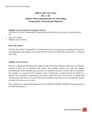
Thus, protocols are required for sharing data on non-dedicated channels. Multiple access protocols can
be subdivided further as –
Data Communication & Networking
SWETA KUMARI BARNWAL 2
1. Random Access Protocol: In this, all stations have same superiority that is no station has more
priority than another station. Any station can send data depending on medium’s state( idle or busy). It
has two features:
1. There is no fixed time for sending data
2. There is no fixed sequence of stations sending data
The Random access protocols are further subdivided as:
(a) ALOHA – It was designed for wireless LAN but is also applicable for shared medium. In this,
multiple stations can transmit data at the same time and can hence lead to collision and data being
garbled.
• Pure Aloha: When a station sends data it waits for an acknowledgement. If the acknowledgement
doesn’t come within the allotted time, then the station waits for a random amount of time called back-
off time (Tb) and re-sends the data. Since different stations wait for different amount of time, the
probability of further collision decreases.
Vulnerable Time = 2* Frame transmission time
Throughput = G exp{-2*G}
Maximum throughput = 0.184 for G=0.5
• Slotted Aloha: It is similar to pure aloha, except that we divide time into slots and sending of data is
allowed only at the beginning of these slots. If a station misses out the allowed time, it must wait for
the next slot. This reduces the probability of collision.
Vulnerable Time = Frame transmission time
Throughput = G exp{-*G}
Maximum throughput = 0.368 for G=1
(b) CSMA – Carrier Sense Multiple Access ensures fewer collisions as the station is required to first
sense the medium (for idle or busy) before transmitting data. If it is idle then it sends data, otherwise it
waits till the channel becomes idle. However there is still chance of collision in CSMA due to
Data Communication & Networking
SWETA KUMARI BARNWAL 3
propagation delay. For example, if station A wants to send data, it will first sense the medium.If it
finds the channel idle, it will start sending data. However, by the time the first bit of data is
transmitted (delayed due to propagation delay) from station A, if station B requests to send data and
senses the medium it will also find it idle and will also send data. This will result in collision of data
from station A and B.
CSMA access modes-
• 1-persistent: The node senses the channel, if idle it sends the data, otherwise it continuously keeps on
checking the medium for being idle and transmits unconditionally(with 1 probability) as soon as the
channel gets idle.
• Non-Persistent: The node senses the channel, if idle it sends the data, otherwise it checks the medium
after a random amount of time (not continuously) and transmits when found idle.
• P-persistent: The node senses the medium, if idle it sends the data with p probability. If the data is
not transmitted ((1-p) probability) then it waits for some time and checks the medium again, now if it
is found idle then it send with p probability. This repeat continues until the frame is sent. It is used in
Wifi and packet radio systems.
• O-persistent: Superiority of nodes is decided beforehand and transmission occurs in that order. If the
medium is idle, node waits for its time slot to send data.
(c) CSMA/CD – Carrier sense multiple access with collision detection. Stations can terminate
transmission of data if collision is detected. The CSMA method does not tell us what to do in case
there is a collision. Carrier sense multiple access with collision detection (CSMA/CD) adds on to the
CSMA algorithm to deal with the collision. In CSMA/CD, the size of a frame must be large enough so
that collision can be detected by sender while sending the frame. So, the frame transmission delay
must be at least two times the maximum propagation delay.
(d) CSMA/CA – Carrier sense multiple access with collision avoidance. The process of collisions
detection involves sender receiving acknowledgement signals. If there is just one signal(its own) then
the data is successfully sent but if there are two signals(its own and the one with which it has collided)
then it means a collision has occurred. To distinguish between these two cases, collision must have a
lot of impact on received signal. However it is not so in wired networks, so CSMA/CA is used in this
case.
CSMA/CA avoids collision by:
1. Interframe space – Station waits for medium to become idle and if found idle it does not
immediately send data (to avoid collision due to propagation delay) rather it waits for a period of time
called Interframe space or IFS. After this time it again checks the medium for being idle. The IFS
duration depends on the priority of station.
2. Contention Window – It is the amount of time divided into slots. If the sender is ready to send data,
it chooses a random number of slots as wait time which doubles every time medium is not found idle.
If the medium is found busy it does not restart the entire process, rather it restarts the timer when the
channel is found idle again.
3. Acknowledgement – The sender re-transmits the data if acknowledgement is not received before
time-out.
2. Controlled Access: In this, the data is sent by that station which is approved by all other stations.
The stations seek information from one another to find which station has the right to send. It allows
Data Communication & Networking
SWETA KUMARI BARNWAL 4
only one node to send at a time, to avoid collision of messages on shared medium.
The three controlled-access methods are:
1. Reservation
2. Polling
3. Token Passing
Reservation
• In the reservation method, a station needs to make a reservation before sending data.
• The time line has two kinds of periods:
1. Reservation interval of fixed time length
2. Data transmission period of variable frames.
• If there are M stations, the reservation interval is divided into M slots, and each station has one slot.
• Suppose if station 1 has a frame to send, it transmits 1 bit during the slot 1. No other station is allowed
to transmit during this slot.
• In general, i th
station may announce that it has a frame to send by inserting a 1 bit into i th
slot. After
all N slots have been checked, each station knows which stations wish to transmit.
• The stations which have reserved their slots transfer their frames in that order.
• After data transmission period, next reservation interval begins.
• Since everyone agrees on who goes next, there will never be any collisions.
The following figure shows a situation with five stations and a five slot reservation frame. In the first
interval, only stations 1, 3, and 4 have made reservations. In the second interval, only station 1 has
made a reservation.
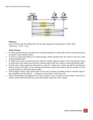
Polling
• Polling process is similar to the roll-call performed in class. Just like the teacher, a controller sends a
message to each node in turn.
• In this, one acts as a primary station(controller) and the others are secondary stations. All data
exchanges must be made through the controller.
• The message sent by the controller contains the address of the node being selected for granting access.
• Although all nodes receive the message but the addressed one responds to it and sends data, if any. If
there is no data, usually a “poll reject”(NAK) message is sent back.
• Problems include high overhead of the polling messages and high dependence on the reliability of the
controller.
Data Communication & Networking
SWETA KUMARI BARNWAL 5
Efficiency
Let Tpoll be the time for polling and Tt be the time required for transmission of data. Then,
Efficiency = Tt/(Tt + Tpoll)
Token Passing
• In token passing scheme, the stations are connected logically to each other in form of ring and access
of stations is governed by tokens.
• A token is a special bit pattern or a small message, which circulate from one station to the next in the
some predefined order.
• In Token ring, token is passed from one station to another adjacent station in the ring whereas incase
of Token bus, each station uses the bus to send the token to the next station in some predefined order.
• In both cases, token represents permission to send. If a station has a frame queued for transmission
when it receives the token, it can send that frame before it passes the token to the next station. If it has
no queued frame, it passes the token simply.
• After sending a frame, each station must wait for all N stations (including itself) to send the token to
their neighbors and the other N – 1 stations to send a frame, if they have one.
• There exist problems like duplication of token or token is lost or insertion of new station, removal of a
station, which need be tackled for correct and reliable operation of this scheme.
Data Communication & Networking
SWETA KUMARI BARNWAL 6
Performance
Performance of token ring can be concluded by 2 parameters:-
1. Delay, which is a measure of time between when a packet is ready and when it is delivered.So, the
average time (delay) required to send a token to the next station = a/N.
2. Throughput, which is a measure of the successful traffic.
Throughput, S = 1/(1 + a/N) for a<1
and
S = 1/{a(1 + 1/N)} for a>1.
where N = number of stations
a = Tp/Tt
(Tp = propagation delay and Tt = transmission delay)
3. Channelization:
In this, the available bandwidth of the link is shared in time, frequency and code to multiple stations to
access channel simultaneously.
• Frequency Division Multiple Access (FDMA) – The available bandwidth is divided into equal bands
so that each station can be allocated its own band. Guard bands are also added so that no two bands
overlap to avoid crosstalk and noise.
• Time Division Multiple Access (TDMA) – In this, the bandwidth is shared between multiple
stations. To avoid collision time is divided into slots and stations are allotted these slots to transmit
data. However, there is an overhead of synchronization as each station needs to know its time slot.
This is resolved by adding synchronization bits to each slot. Another issue with TDMA is propagation
delay which is resolved by addition of guard bands.
• Code Division Multiple Access (CDMA) – One channel carries all transmissions simultaneously.
There is neither division of bandwidth nor division of time. For example, if there are many people in a
room all speaking at the same time, then also perfect reception of data is possible if only two person
Data Communication & Networking
SWETA KUMARI BARNWAL 7
speak the same language. Similarly, data from different stations can be transmitted simultaneously in
different code languages.
Wireless LAN
A wireless local area network (WLAN) is a local area network (LAN) that doesn't rely on
wired Ethernet connections. A WLAN can be either an extension to a current wired network or an
alternative to it.
WLANs have data transfer speeds ranging from 1 to 54Mbps, with some manufacturers offering
proprietary 108Mbps solutions. The 802.11n standard can reach 300 to 600Mbps.
Because the wireless signal is broadcast so everybody nearby can share it, several security precautions
are necessary to ensure only authorized users can access your WLAN.
A WLAN signal can be broadcast to cover an area ranging in size from a small office to a large campus.
Most commonly, a WLAN access point provides access within a radius of 65 to 300 feet.
WLAN types
Private home or small business WLAN
Commonly, a home or business WLAN employs one or two access points to broadcast a signal around a
100- to 200-foot radius. You can find equipment for installing a home WLAN in many retail stores.
With few exceptions, hardware in this category subscribes to the 802.11a, b, or g standards (also known
as Wi-Fi); some home and office WLANs now adhere to the new 802.11n standard. Also, because of
security concerns, many home and office WLANs adhere to the Wi-Fi Protected Access 2 (WPA2)
standard.
Enterprise class WLAN
An enterprise class WLAN employs a large number of individual access points to broadcast the signal to
a wide area. The access points have more features than home or small office WLAN equipment, such as
better security, authentication, remote management, and tools to help integrate with existing networks.
These access points have a larger coverage area than home or small office equipment, and are designed
to work together to cover a much larger area. This equipment can adhere to the 802.11a, b, g, or n
standard, or to security-refining standards, such as 802.1x and WPA2.
WLAN standards
Several standards for WLAN hardware exist:
WLAN
standard Pros Cons
802.11a
• Faster data transfer rates (up to
54Mbps)
• Supports more simultaneous
connections
• Less susceptible to interference
• Short range (60-100 feet)
• Less able to penetrate physical
barriers
Data Communication & Networking
SWETA KUMARI BARNWAL 8
WLAN
standard Pros Cons
802.11b
• Better at penetrating physical barriers
• Longest range (70-150 feet)
• Hardware is usually less
expensive
• Slower data transfer rates (up
to 11Mbps)
• Doesn't support as many
simultaneous connections
• More susceptible to
interference
802.11g
• Faster data transfer rates (up to
54Mbps)
• Better range than 802.11b (65-120
feet)
• More susceptible to
interference
802.11n
The 802.11n standard was recently ratified by the Institute of Electrical and
Electronics Engineers (IEEE), as compared to the previous three standards.
Though specifications may change, it is expected to allow data transfer rates up
to 600Mbps, and may offer larger ranges.
Security standards
The 802.11x standards provide some basic security, but are becoming less adequate as use of wireless
networking spreads. Following are security standards that extend or replace the basic standard:
WEP (Wired Equivalent Privacy)
WEP encrypts data traffic between the wireless access point and the client computer, but doesn't
actually secure either end of the transmission. WEP's encryption level is relatively weak (only 40 to
128 bits). Many analysts consider WEP security to be weak and easy to crack.
WPA (Wi-Fi Protected Access)
WPA implements higher security and addresses the flaws in WEP, but is intended to be only an
intermediate measure until further 802.11i security measures are developed.
IEEE 802.11 Wireless LAN (WLAN)
The Wireless local area network (WLAN) protocol, IEEE 802.11, and associated technologies, such
as the 802.11X protocol, allow secure high-speed wireless network access and mobile access to a
network infrastructure. Until the recent development of this technology, in order to obtain high-speed
network access, we needed to be physically connected to the LAN with some type of wiring. Not
anymore.
Some of the Wireless LAN Technologies are shown in the figure below:
Data Communication & Networking
SWETA KUMARI BARNWAL 9
IEEE 802.11 Architecture
The difference between a portable and mobile station is that a portable station moves from point to point
but is only used at a fixed point. Mobile stations access the LAN during movement.
When two or more stations come together to communicate with each other, they form a Basic Service
Set (BSS). The minimum BSS consists of two stations. 802.11 LANs use the BSS as the standard
building block.
A BSS that stands alone and is not connected to a base is called an Independent Basic Service Set
(IBSS) or is referred to as an Ad-Hoc Network. An ad-hoc network is a network where stations
communicate only peer to peer. There is no base and no one gives permission to talk. Mostly these
networks are spontaneous and can be set up rapidly. Ad-Hoc or IBSS networks are characteristically
limited both temporally and spatially.
Data Communication & Networking
SWETA KUMARI BARNWAL 10
Adhoc Mode Infrastructure Mode
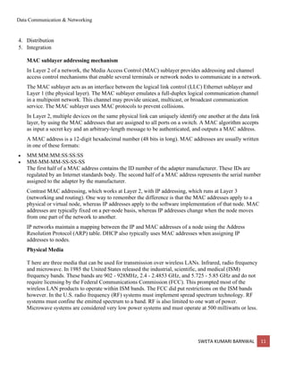
Adhoc Mode: When BSS's are interconnected the network becomes one with infrastructure. 802.11
infrastructure has several elements. Two or more BSS's are interconnected using a Distribution System
or DS. This concept of DS increases network coverage. Each BSS becomes a component of an
extended, larger network. Entry to the DS is accomplished with the use of Access Points (AP). An
access point is a station, thus addressable. So, data moves between the BSS and the DS with the help of
these access points.
Creating large and complex networks using BSS's and DS's leads us to the next level of hierarchy, the
Extended Service Set or ESS. The beauty of the ESS is the entire network looks like an independent
basic service set to the Logical Link Control layer (LLC). This means that stations within the ESS can
communicate or even move between BSS′s transparently to the LLC.
Infrastructure Mode: One of the requirements of IEEE 802.11 is that it can be used with existing
wired networks. 802.11 solved this challenge with the use of a Portal. A portal is the logical integration
between wired LANs and 802.11. It also can serve as the access point to the DS. All data going to an
802.11 LAN from an 802.X LAN must pass through a portal. It thus functions as bridge between wired
and wireless.
The implementation of the DS is not specified by 802.11. Therefore, a distribution system may be
created from existing or new technologies. A point-to-point bridge connecting LANs in two separate
buildings could become a DS.
While the implementation for the DS is not specified, 802.11 does specify the services, which the DS
must support. Services are divided into two sections
1. Station Services (SS)
2. Distribution System Services (DSS).
There are five services provided by the DSS
1. Association
2. Reassociation
3. Disassociation
Data Communication & Networking
SWETA KUMARI BARNWAL 11
4. Distribution
5. Integration
MAC sublayer addressing mechanism
In Layer 2 of a network, the Media Access Control (MAC) sublayer provides addressing and channel
access control mechanisms that enable several terminals or network nodes to communicate in a network.
The MAC sublayer acts as an interface between the logical link control (LLC) Ethernet sublayer and
Layer 1 (the physical layer). The MAC sublayer emulates a full-duplex logical communication channel
in a multipoint network. This channel may provide unicast, multicast, or broadcast communication
service. The MAC sublayer uses MAC protocols to prevent collisions.
In Layer 2, multiple devices on the same physical link can uniquely identify one another at the data link
layer, by using the MAC addresses that are assigned to all ports on a switch. A MAC algorithm accepts
as input a secret key and an arbitrary-length message to be authenticated, and outputs a MAC address.
A MAC address is a 12-digit hexadecimal number (48 bits in long). MAC addresses are usually written
in one of these formats:
• MM:MM:MM:SS:SS:SS
• MM-MM-MM-SS-SS-SS
The first half of a MAC address contains the ID number of the adapter manufacturer. These IDs are
regulated by an Internet standards body. The second half of a MAC address represents the serial number
assigned to the adapter by the manufacturer.
Contrast MAC addressing, which works at Layer 2, with IP addressing, which runs at Layer 3
(networking and routing). One way to remember the difference is that the MAC addresses apply to a
physical or virtual node, whereas IP addresses apply to the software implementation of that node. MAC
addresses are typically fixed on a per-node basis, whereas IP addresses change when the node moves
from one part of the network to another.
IP networks maintain a mapping between the IP and MAC addresses of a node using the Address
Resolution Protocol (ARP) table. DHCP also typically uses MAC addresses when assigning IP
addresses to nodes.
Physical Media
T here are three media that can be used for transmission over wireless LANs. Infrared, radio frequency
and microwave. In 1985 the United States released the industrial, scientific, and medical (ISM)
frequency bands. These bands are 902 - 928MHz, 2.4 - 2.4853 GHz, and 5.725 - 5.85 GHz and do not
require licensing by the Federal Communications Commission (FCC). This prompted most of the
wireless LAN products to operate within ISM bands. The FCC did put restrictions on the ISM bands
however. In the U.S. radio frequency (RF) systems must implement spread spectrum technology. RF
systems must confine the emitted spectrum to a band. RF is also limited to one watt of power.
Microwave systems are considered very low power systems and must operate at 500 milliwatts or less.
Data Communication & Networking
SWETA KUMARI BARNWAL 12
Infrared
I nfrared systems are simple in design and therefore inexpensive. They use the same signal frequencies
used on fiber optic links. IR systems detect only the amplitude of the signal and so interference is
greatly reduced. These systems are not bandwidth limited and thus can achieve transmission speeds
greater than the other systems. Infrared transmission operates in the light spectrum and does not require
a license from the FCC to operate, another attractive feature. There are two conventional ways to set up
an IR LAN. The infrared transmissions can be aimed. This gives a good range of a couple of kilometer
and can be used outdoors. It also offers the highest bandwidth and throughput. The other way is to
transmit omni-directionally and bounce the signals off of everything in every direction. This reduces
coverage to 30 - 60 feet, but it is an area coverage. IR technology was initially very popular because it
delivered high data rates and relatively cheap price. The drawbacks to IR systems are that the
transmission spectrum is shared with the sun and other things such as fluorescent lights. If there is
enough interference from other sources it can render the LAN useless. IR systems require an
unobstructed line of sight (LOS). IR signals cannot penetrate opaque objects. This means that walls,
dividers, curtains, or even fog can obstruct the signal. InfraLAN is an example of wireless LANs using
infrared technology.
Microwave
M icrowave (MW) systems operate at less than 500 milliwatts of power in compliance with FCC
regulations. MW systems are by far the fewest on the market. They use narrow-band transmission with
single frequency modualtion and are set up mostly in the 5.8GHz band. The big advantage to MW
systems is higher throughput achieved because they do not have the overhead involved with spread
spectrum systems. RadioLAN is an example of systems with microwave technology.
Radio
Radio frequency systems must use spread spectrum technology in the United States. This spread
spectrum technology currently comes in two types: direct sequence spread spectrum (DSSS) and
frequency hopping spread spectrum (FHSS). There is a lot of overhead involved with spread spectrum
and so most of the DSSS and FHSS systems have historically had lower data rates than IR or MW.
Bluetooth
Lower Stack Layers
The lower layers are the basic core specifications that describe how Bluetooth works. The base of the
Bluetooth protocol stack is the radio layer, or module. The radio layer describes the physical characteristics of
the transceiver. It is responsible for modulation/demodulation of data for transmitting or receiving over radio
frequencies in the 2.4 GHz band. This is the physical wireless connection. It splits the transmission band into
79 channels and performs fast frequency hopping (1600 hops/sec) for security.
Above the radio layer is the baseband and link controller/link manager protocol (LMP). Perhaps the best way to
think of these layers is that the baseband is responsible for properly formatting data for transmission to and
Data Communication & Networking
SWETA KUMARI BARNWAL 13
from the radio. It defines the timing, framing, packets, and flow control on the link. The link manager
controller translates the host controller interface (HCI) commands from the upper stack, and establishes and
maintains the link. It is responsible for managing the connection, enforcing fairness among slaves in the
piconet, and provides for power management.
Upper Stack Layers
The upper stack layers consist of profile specifications that focus on how to build devices that will
communicate with each other, using the core technology.
The host controller interface (HCI) serves as the interface between the software part of the system and the
hardware (i.e., the device driver).
Data Communication & Networking
SWETA KUMARI BARNWAL 14
The L2CAP (logical link control and adaptation protocol) layer is above the HCI in the upper stack. Among
other functions, it plays a central role in communication between the upper and lower layers of the Bluetooth
stack. It keeps track of where data packets come from and where they should go. It is a required part of every
Bluetooth system.
Above the L2CAP layer, the protocol stack is not as linearly ordered. Still, the service discovery protocol
(SDP) is important to mention because it exists independently of other higher-level protocol layers. It provides
the interface to the link controller and allows for interoperability between Bluetooth devices.
BT LogoOf course, it is not required to partition the Bluetooth stack as shown in Figure 1. Bluetooth headsets,
for example, combine the module and host portions of the stack on one processor to meet self-containment and
small size needs. In such devices, the HCI may not be implemented at all unless device testing is required.
The Bluetooth architecture, showing all the major layers in the Bluetooth system, are depicted in the
Fig. 5.8.3. The layers below can be considered to be different hurdles in an obstacle course. This is
because all the layers function one after the other. One layer comes into play only after the data has been
through the previous layer.
• Radio: The Radio layer defines the requirements for a Bluetooth transceiver operating in the 2.4 GHz ISM
band.
• Baseband: The Baseband layer describes the specification of the Bluetooth Link Controller (LC), which
carries out the baseband protocols and other low-level link routines. It specifies Piconet/Channel definition,
“Low-level” packet definition, Channel sharing
• LMP: The Link Manager Protocol (LMP) is used by the Link Managers (on either side) for link set-up and
control.
• HCI: The Host Controller Interface (HCI) provides a command interface to the Baseband Link Controller and
Link Manager, and access to hardware status and control registers.
• L2CAP: Logical Link Control and Adaptation Protocol (L2CAP) supports higher level protocol multiplexing,
packet segmentation and reassembly, and the conveying of quality of service information.
• RFCOMM: The RFCOMM protocol provides emulation of serial ports over the L2CAP protocol. The
protocol is based on the ETSI standard TS 07.10.
• SDP: The Service Discovery Protocol (SDP) provides a means for applications to discover, which services
are provided by or available through a Bluetooth device. It also allows applications to determine the
characteristics of those available services.
Now we shall be study each layer in detail (in next few sections) so that we come to know the function of each
layer.
WiMAX
WiMAX is one of the hottest broadband wireless technologies around today. WiMAX systems are
expected to deliver broadband access services to residential and enterprise customers in an economical
way.
Loosely, WiMax is a standardized wireless version of Ethernet intended primarily as an alternative to
wire technologies (such as Cable Modems, DSL and T1/E1 links) to provide broadband access to
customer premises.
Data Communication & Networking
SWETA KUMARI BARNWAL 15
More strictly, WiMAX is an industry trade organization formed by leading communications,
component, and equipment companies to promote and certify compatibility and interoperability of
broadband wireless access equipment that conforms to the IEEE 802.16 and ETSI HIPERMAN
standards.
WiMAX would operate similar to WiFi, but at higher speeds over greater distances and for a greater
number of users. WiMAX has the ability to provide service even in areas that are difficult for wired
infrastructure to reach and the ability to overcome the physical limitations of traditional wired
infrastructure.
WiMAX was formed in April 2001, in anticipation of the publication of the original 10-66 GHz IEEE
802.16 specifications. WiMAX is to 802.16 as the WiFi Alliance is to 802.11.
WiMAX is
• Acronym for Worldwide Interoperability for Microwave Access.
• Based on Wireless MAN technology.
• A wireless technology optimized for the delivery of IP centric services over a wide area.
• A scalable wireless platform for constructing alternative and complementary broadband networks.
• A certification that denotes interoperability of equipment built to the IEEE 802.16 or compatible
standard. The IEEE 802.16 Working Group develops standards that address two types of usage models
−
o A fixed usage model (IEEE 802.16-2004).
o A portable usage model (IEEE 802.16e).
• WiMAX is such an easy term that people tend to use it for the 802.16 standards and technology
themselves, although strictly it applies only to systems that meet specific conformance criteria laid down
by the WiMAX Forum.
• The 802.16a standard for 2-11 GHz is a wireless metropolitan area network (MAN) technology that will
provide broadband wireless connectivity to Fixed, Portable and Nomadic devices.
• It can be used to connect 802.11 hot spots to the Internet, provide campus connectivity, and provide a
wireless alternative to cable and DSL for last mile broadband access.
WiMax Speed and Range
WiMAX is expected to offer initially up to about 40 Mbps capacity per wireless channel for both fixed
and portable applications, depending on the particular technical configuration chosen, enough to support
hundreds of businesses with T-1 speed connectivity and thousands of residences with DSL speed
connectivity. WiMAX can support voice and video as well as Internet data.
WiMax developed to provide wireless broadband access to buildings, either in competition to existing
wired networks or alone in currently unserved rural or thinly populated areas. It can also be used to
connect WLAN hotspots to the Internet. WiMAX is also intended to provide broadband connectivity to
mobile devices. It would not be as fast as in these fixed applications, but expectations are for about 15
Mbps capacity in a 3 km cell coverage area.
Data Communication & Networking
SWETA KUMARI BARNWAL 16
With WiMAX, users could really cut free from today's Internet access arrangements and be able to go
online at broadband speeds, almost wherever they like from within a MetroZone.
WiMAX could potentially be deployed in a variety of spectrum bands: 2.3GHz, 2.5GHz, 3.5GHz, and
5.8GHz.
Why WiMax?
• WiMAX can satisfy a variety of access needs. Potential applications include extending broadband
capabilities to bring them closer to subscribers, filling gaps in cable, DSL and T1 services, WiFi, and
cellular backhaul, providing last-100 meter access from fibre to the curb and giving service providers
another cost-effective option for supporting broadband services.
• WiMAX can support very high bandwidth solutions where large spectrum deployments (i.e. >10 MHz)
are desired using existing infrastructure keeping costs down while delivering the bandwidth needed to
support a full range of high-value multimedia services.
• WiMAX can help service providers meet many of the challenges they face due to increasing customer
demands without discarding their existing infrastructure investments because it has the ability to
seamlessly interoperate across various network types.
• WiMAX can provide wide area coverage and quality of service capabilities for applications ranging
from real-time delay-sensitive voice-over-IP (VoIP) to real-time streaming video and non-real-time
downloads, ensuring that subscribers obtain the performance they expect for all types of
communications.
• WiMAX, which is an IP-based wireless broadband technology, can be integrated into both wide-area
third-generation (3G) mobile and wireless and wireline networks allowing it to become part of a
seamless anytime, anywhere broadband access solution.
Ultimately, WiMAX is intended to serve as the next step in the evolution of 3G mobile phones, via a
potential combination of WiMAX and CDMA standards called 4G.
WiMAX Goals
A standard by itself is not enough to enable mass adoption. WiMAX has stepped forward to help solve
barriers to adoption, such as interoperability and cost of deployment. WiMAX will help ignite the
wireless MAN industry by defining and conducting interoperability testing and labeling vendor systems
with a "WiMAX Certified™" label once testing has been completed successfully.
Cellular Telephone System
As shown in Fig. a cellular system comprises the following basic components:
• Mobile Stations (MS): Mobile handsets, which is used by an user to communicate with another user
• Cell: Each cellular service area is divided into small regions called cell (5 to 20 Km)
• Base Stations (BS): Each cell contains an antenna, which is controlled by a small office.
Data Communication & Networking
SWETA KUMARI BARNWAL 17
Mobile Switching Center (MSC): Each base station is controlled by a switching office, called mobile
switching center
Cellular telephone systems rely on an intelligent allocation and reuse of channels. Each base station is
given a group of radio channels to be used within a cell. Base stations in neighbouring cells are assigned
completely different set of channel frequencies. By limiting the coverage areas, called footprints, within
cell boundaries, the same set of channels may be used to cover different cells separated from one
another by a distance large enough to keep interference level within tolerable limits as shown in Fig,
Cells with the same letter use the same set of frequencies, called reusing cells. N cells which collectively
use the available frequencies (S = k.N) is known as cluster. If a cluster is replicated M times within a
system, then total number duplex channels (capacity) is C = M.k.N= M.S.
As the demand increases in a particular region, the number of stations can be increased by replacing a
cell with a cluster as shown in Fig. 5.9.3. Here cell C has been replaced with a cluster. However, this
will be possible only by decreasing the transmitting power of the base stations to avoid interference.
Mobility Management
A MS is assigned a home network, commonly known as location area. When an MS migrates out of
its current BS into the footprint of another, a procedure is performed to maintain service continuity,
Data Communication & Networking
SWETA KUMARI BARNWAL 18
known as Handoff management. An agent in the home network, called home agent, keeps track of the
current location of the MS. The procedure to keep track of the user’s current location is referred to as
Location management. Handoff management and location management together are referred to as
Mobility management.
Handoff: At any instant, each mobile station is logically in a cell and under the control of the cell’s
base station. When a mobile station moves out of a cell, the base station notices the MS’s signal fading
away and requests all the neighbouring BSs to report the strength they are receiving. The BS then
transfers ownership to the cell getting the strongest signal and the MSC changes the channel carrying the
call. The process is called handoff. There are two types of handoff; Hard Handoff and Soft Handoff. In
a hard handoff, which was used in the early systems, a MS communicates with one BS. As a MS
moves from cell A to cell B, the communication between the MS and base station of cell A is first
broken before communication is started between the MS and the base station of B. As a consequence,
the transition is not smooth. For smooth transition from one cell (say A) to another (say B), an MS
continues to talk to both A and B. As the MS moves from cell A to cell B, at some point the
communication is broken with the old base station of cell A. This is known as soft handoff.
Satellite Networks
Microwave frequencies, which travel in straight lines, are commonly used for wideband
communication. The curvature of the earth results in obstruction of the signal between two earth stations
and the signal also gets attenuated with the distance it traverses. To overcome both the problems, it is
necessary to use a repeater, which can receive a signal from one earth station, amplify it, and retransmit
it to another earth station. Larger the height of a repeater from the surface of the earth, longer is the
distance of line-of-sight communication. Satellite networks were originally developed to provide long-
distance telephone service. So, for communication over long distances, satellites are a natural choice for
use as repeaters in the sky. In this lesson, we shall discuss different aspects of satellite networks.
Data Communication & Networking
SWETA KUMARI BARNWAL 19
The altitude of LEO satellites is in the range of 500 to 1500 Km with a rotation period of 90 to 120
min and round trip delay of less than 20 ms. The satellites rotate in polar orbits with a rotational speed
of 20,000 to 25,000 Km. As the footprint of LEO satellites is a small area of about 8000 Km diameter, it
is necessary to have a constellation of satellites.
Data Communication & Networking
SWETA KUMARI BARNWAL 20
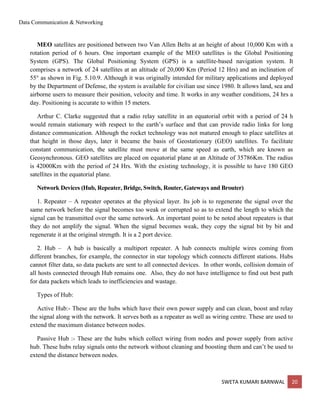
MEO satellites are positioned between two Van Allen Belts at an height of about 10,000 Km with a
rotation period of 6 hours. One important example of the MEO satellites is the Global Positioning
System (GPS). The Global Positioning System (GPS) is a satellite-based navigation system. It
comprises a network of 24 satellites at an altitude of 20,000 Km (Period 12 Hrs) and an inclination of
55° as shown in Fig. 5.10.9. Although it was originally intended for military applications and deployed
by the Department of Defense, the system is available for civilian use since 1980. It allows land, sea and
airborne users to measure their position, velocity and time. It works in any weather conditions, 24 hrs a
day. Positioning is accurate to within 15 meters.
Arthur C. Clarke suggested that a radio relay satellite in an equatorial orbit with a period of 24 h
would remain stationary with respect to the earth’s surface and that can provide radio links for long
distance communication. Although the rocket technology was not matured enough to place satellites at
that height in those days, later it became the basis of Geostationary (GEO) satellites. To facilitate
constant communication, the satellite must move at the same speed as earth, which are known as
Geosynchronous. GEO satellites are placed on equatorial plane at an Altitude of 35786Km. The radius
is 42000Km with the period of 24 Hrs. With the existing technology, it is possible to have 180 GEO
satellites in the equatorial plane.
Network Devices (Hub, Repeater, Bridge, Switch, Router, Gateways and Brouter)
1. Repeater – A repeater operates at the physical layer. Its job is to regenerate the signal over the
same network before the signal becomes too weak or corrupted so as to extend the length to which the
signal can be transmitted over the same network. An important point to be noted about repeaters is that
they do not amplify the signal. When the signal becomes weak, they copy the signal bit by bit and
regenerate it at the original strength. It is a 2 port device.
2. Hub – A hub is basically a multiport repeater. A hub connects multiple wires coming from
different branches, for example, the connector in star topology which connects different stations. Hubs
cannot filter data, so data packets are sent to all connected devices. In other words, collision domain of
all hosts connected through Hub remains one. Also, they do not have intelligence to find out best path
for data packets which leads to inefficiencies and wastage.
Types of Hub:
Active Hub:- These are the hubs which have their own power supply and can clean, boost and relay
the signal along with the network. It serves both as a repeater as well as wiring centre. These are used to
extend the maximum distance between nodes.
Passive Hub :- These are the hubs which collect wiring from nodes and power supply from active
hub. These hubs relay signals onto the network without cleaning and boosting them and can’t be used to
extend the distance between nodes.
Data Communication & Networking
SWETA KUMARI BARNWAL 21
3. Bridge – A bridge operates at data link layer. A bridge is a repeater, with add on the functionality
of filtering content by reading the MAC addresses of source and destination. It is also used for
interconnecting two LANs working on the same protocol. It has a single input and single output port,
thus making it a 2 port device.
Types of Bridges
Transparent Bridges:- These are the bridge in which the stations are completely unaware of the
bridge’s existence i.e. whether or not a bridge is added or deleted from the network, reconfiguration
of
the stations is unnecessary. These bridges make use of two processes i.e. bridge forwarding and
bridge learning.
Source Routing Bridges:- In these bridges, routing operation is performed by source station and the
frame specifies which route to follow. The hot can discover frame by sending a special frame called
discovery frame, which spreads through the entire network using all possible paths to destination.
4. Switch – A switch is a multiport bridge with a buffer and a design that can boost its efficiency(a
large number of ports imply less traffic) and performance. A switch is a data link layer device. The
switch can perform error checking before forwarding data, that makes it very efficient as it does not
forward packets that have errors and forward good packets selectively to correct port only. In other
words, switch divides collision domain of hosts, but broadcast domain remains same.
5. Routers – A router is a device like a switch that routes data packets based on their IP addresses.
Router is mainly a Network Layer device. Routers normally connect LANs and WANs together and
have a dynamically updating routing table based on which they make decisions on routing the data
packets. Router divide broadcast domains of hosts connected through it.
6. Gateway – A gateway, as the name suggests, is a passage to connect two networks together that
may work upon different networking models. They basically work as the messenger agents that take
data from one system, interpret it, and transfer it to another system. Gateways are also called protocol
converters and can operate at any network layer. Gateways are generally more complex than switch or
router.
7. Brouter – It is also known as bridging router is a device which combines features of both bridge
and router. It can work either at data link layer or at network layer. Working as router, it is capable of
routing packets across networks and working as bridge, it is capable of filtering local area network
traffic.
Virtual LAN (VLAN)
Data Communication & Networking
SWETA KUMARI BARNWAL 22
Virtual LAN (VLAN) is a concept in which we can divide the devices logically on layer 2 (data link
layer). Generally, layer 3 devices divides broadcast domain but broadcast domain can be divided by
switches using the concept of VLAN.
A broadcast domain is a network segment in which if a device broadcast a packet then all the devices in
the same broadcast domain will receive it. The devices in the same broadcast domain will receive all the
broadcast packet but it is limited to switches only as routers don’t forward out the broadcast packet.To
forward out the packets to different VLAN (from one VLAN to another) or broadcast domain, inter
Vlan routing is needed. Through VLAN, different small size sub networks are created which are
comparatively easy to handle.

More Related Content

What's hot

Structure of switches
Structure of switchesStructure of switches
Structure of switchesAnam Sana
 
Computer Network - Network Layer
Computer Network - Network LayerComputer Network - Network Layer
Computer Network - Network LayerManoj Kumar
 
Ch 18 intro to network layer - section 1
Ch 18   intro to network layer - section 1Ch 18   intro to network layer - section 1
Ch 18 intro to network layer - section 1Hossam El-Deen Osama
 
Routing, Different types of forwarding technique
Routing, Different types of forwarding techniqueRouting, Different types of forwarding technique
Routing, Different types of forwarding techniquerajib_
 
Chapter10 switching
Chapter10 switchingChapter10 switching
Chapter10 switchingSuneel Varma
 
Controlled Access Protocols
Controlled Access ProtocolsControlled Access Protocols
Controlled Access ProtocolsPruthviraj Konu
 
Lab Seminar 2009 12 01 Message Drop Reduction And Movement
Lab Seminar 2009 12 01  Message Drop Reduction And MovementLab Seminar 2009 12 01  Message Drop Reduction And Movement
Lab Seminar 2009 12 01 Message Drop Reduction And Movementtharindanv
 
Network Layer,Computer Networks
Network Layer,Computer NetworksNetwork Layer,Computer Networks
Network Layer,Computer Networksguesta81d4b
 
Ch 18 intro to network layer - section 2
Ch 18   intro to network layer - section 2Ch 18   intro to network layer - section 2
Ch 18 intro to network layer - section 2Hossam El-Deen Osama
 
Network layer new
Network layer newNetwork layer new
Network layer newreshmadayma
 
Switching concepts Data communication and networks
Switching concepts Data communication and networksSwitching concepts Data communication and networks
Switching concepts Data communication and networksNt Arvind
 
Multiple Access Protocal
Multiple Access ProtocalMultiple Access Protocal
Multiple Access Protocaltes31
 
Lecture 3 network layer
Lecture 3 network layerLecture 3 network layer
Lecture 3 network layerRonoh Kennedy
 
Computer networks unit ii
Computer networks    unit iiComputer networks    unit ii
Computer networks unit iiJAIGANESH SEKAR
 
Network layer ip address assignment and routing
Network layer ip address assignment and routingNetwork layer ip address assignment and routing
Network layer ip address assignment and routingHamzahMohammed4
 

What's hot (20)

Structure of switches
Structure of switchesStructure of switches
Structure of switches
 
Computer Network - Network Layer
Computer Network - Network LayerComputer Network - Network Layer
Computer Network - Network Layer
 
Ch 18 intro to network layer - section 1
Ch 18   intro to network layer - section 1Ch 18   intro to network layer - section 1
Ch 18 intro to network layer - section 1
 
Network Layer
Network LayerNetwork Layer
Network Layer
 
Routing, Different types of forwarding technique
Routing, Different types of forwarding techniqueRouting, Different types of forwarding technique
Routing, Different types of forwarding technique
 
Chapter10 switching
Chapter10 switchingChapter10 switching
Chapter10 switching
 
Controlled Access Protocols
Controlled Access ProtocolsControlled Access Protocols
Controlled Access Protocols
 
Lab Seminar 2009 12 01 Message Drop Reduction And Movement
Lab Seminar 2009 12 01  Message Drop Reduction And MovementLab Seminar 2009 12 01  Message Drop Reduction And Movement
Lab Seminar 2009 12 01 Message Drop Reduction And Movement
 
Network Layer
Network LayerNetwork Layer
Network Layer
 
Network Layer,Computer Networks
Network Layer,Computer NetworksNetwork Layer,Computer Networks
Network Layer,Computer Networks
 
Ch 18 intro to network layer - section 2
Ch 18   intro to network layer - section 2Ch 18   intro to network layer - section 2
Ch 18 intro to network layer - section 2
 
Network layer new
Network layer newNetwork layer new
Network layer new
 
Routing protocols
Routing protocolsRouting protocols
Routing protocols
 
Routing
RoutingRouting
Routing
 
Switching concepts Data communication and networks
Switching concepts Data communication and networksSwitching concepts Data communication and networks
Switching concepts Data communication and networks
 
Multiple Access Protocal
Multiple Access ProtocalMultiple Access Protocal
Multiple Access Protocal
 
Lecture 3 network layer
Lecture 3 network layerLecture 3 network layer
Lecture 3 network layer
 
Computer networks unit ii
Computer networks    unit iiComputer networks    unit ii
Computer networks unit ii
 
Week2.1
Week2.1Week2.1
Week2.1
 
Network layer ip address assignment and routing
Network layer ip address assignment and routingNetwork layer ip address assignment and routing
Network layer ip address assignment and routing
 

Similar to Data Communication & Networking Multiple Access Protocols

multiacess protocol
multiacess protocolmultiacess protocol
multiacess protocolKanwal Khan
 
Multiple access protocol
Multiple access protocolMultiple access protocol
Multiple access protocolNowrinJahanSiam
 
Introduction to Multiple Access Protocol.pptx
Introduction to Multiple Access Protocol.pptxIntroduction to Multiple Access Protocol.pptx
Introduction to Multiple Access Protocol.pptxupamatechverse
 
Computer Network presention Pravin Bhargav , Surykant Ratrey (1).pptx
Computer Network presention  Pravin Bhargav , Surykant Ratrey (1).pptxComputer Network presention  Pravin Bhargav , Surykant Ratrey (1).pptx
Computer Network presention Pravin Bhargav , Surykant Ratrey (1).pptxPravinbhargav
 
the Multiple Access SLIDE for university students
the Multiple Access SLIDE for university studentsthe Multiple Access SLIDE for university students
the Multiple Access SLIDE for university studentsnovrain1
 
WHAT IS MAC-1 presentation for information .pptx
WHAT IS MAC-1 presentation for information  .pptxWHAT IS MAC-1 presentation for information  .pptx
WHAT IS MAC-1 presentation for information .pptxSaqlainKhan39
 
Multiple Access Methods
Multiple Access MethodsMultiple Access Methods
Multiple Access MethodsPrateek Soni
 
Multiple access protocols in data communication networks
Multiple access protocols in data communication networksMultiple access protocols in data communication networks
Multiple access protocols in data communication networksNt Arvind
 
UNIT-V Wireless Communication.pdf
UNIT-V Wireless Communication.pdfUNIT-V Wireless Communication.pdf
UNIT-V Wireless Communication.pdfvadasairaju143
 
Multiole acccess
Multiole acccessMultiole acccess
Multiole acccessjasscheema
 
Computer Network MAC Layer Notes as per RGPV syllabus
Computer Network MAC Layer Notes as per RGPV syllabusComputer Network MAC Layer Notes as per RGPV syllabus
Computer Network MAC Layer Notes as per RGPV syllabusNANDINI SHARMA
 
CN R16 -UNIT-4.pdf
CN R16 -UNIT-4.pdfCN R16 -UNIT-4.pdf
CN R16 -UNIT-4.pdfJoshuaeeda1
 
Multiple Access Techniques
Multiple Access TechniquesMultiple Access Techniques
Multiple Access Techniquesinayat khan
 
CN Unit 2 - cs8591.pptx
CN Unit 2 - cs8591.pptxCN Unit 2 - cs8591.pptx
CN Unit 2 - cs8591.pptxPondinesh2
 
Jaimin chp-4 - media access sub-layer- 2011 batch
Jaimin   chp-4 - media access sub-layer- 2011 batchJaimin   chp-4 - media access sub-layer- 2011 batch
Jaimin chp-4 - media access sub-layer- 2011 batchJaimin Jani
 
CSC 424 -Lecture 5n8 2022.pptx
CSC 424 -Lecture 5n8 2022.pptxCSC 424 -Lecture 5n8 2022.pptx
CSC 424 -Lecture 5n8 2022.pptxNoraNjepuome3
 
SLOTTED ALOHA and pure aloha are the category of aloha
SLOTTED ALOHA and pure aloha are the category of alohaSLOTTED ALOHA and pure aloha are the category of aloha
SLOTTED ALOHA and pure aloha are the category of alohaAkshathaM29
 

Similar to Data Communication & Networking Multiple Access Protocols (20)

multiacess protocol
multiacess protocolmultiacess protocol
multiacess protocol
 
Multiple access protocol
Multiple access protocolMultiple access protocol
Multiple access protocol
 
clas 8
clas 8clas 8
clas 8
 
Introduction to Multiple Access Protocol.pptx
Introduction to Multiple Access Protocol.pptxIntroduction to Multiple Access Protocol.pptx
Introduction to Multiple Access Protocol.pptx
 
Computer Network presention Pravin Bhargav , Surykant Ratrey (1).pptx
Computer Network presention  Pravin Bhargav , Surykant Ratrey (1).pptxComputer Network presention  Pravin Bhargav , Surykant Ratrey (1).pptx
Computer Network presention Pravin Bhargav , Surykant Ratrey (1).pptx
 
Data link control notes
Data link control notesData link control notes
Data link control notes
 
the Multiple Access SLIDE for university students
the Multiple Access SLIDE for university studentsthe Multiple Access SLIDE for university students
the Multiple Access SLIDE for university students
 
WHAT IS MAC-1 presentation for information .pptx
WHAT IS MAC-1 presentation for information  .pptxWHAT IS MAC-1 presentation for information  .pptx
WHAT IS MAC-1 presentation for information .pptx
 
Multiple Access Methods
Multiple Access MethodsMultiple Access Methods
Multiple Access Methods
 
Multiple access protocols in data communication networks
Multiple access protocols in data communication networksMultiple access protocols in data communication networks
Multiple access protocols in data communication networks
 
dcn.pdf
dcn.pdfdcn.pdf
dcn.pdf
 
UNIT-V Wireless Communication.pdf
UNIT-V Wireless Communication.pdfUNIT-V Wireless Communication.pdf
UNIT-V Wireless Communication.pdf
 
Multiole acccess
Multiole acccessMultiole acccess
Multiole acccess
 
Computer Network MAC Layer Notes as per RGPV syllabus
Computer Network MAC Layer Notes as per RGPV syllabusComputer Network MAC Layer Notes as per RGPV syllabus
Computer Network MAC Layer Notes as per RGPV syllabus
 
CN R16 -UNIT-4.pdf
CN R16 -UNIT-4.pdfCN R16 -UNIT-4.pdf
CN R16 -UNIT-4.pdf
 
Multiple Access Techniques
Multiple Access TechniquesMultiple Access Techniques
Multiple Access Techniques
 
CN Unit 2 - cs8591.pptx
CN Unit 2 - cs8591.pptxCN Unit 2 - cs8591.pptx
CN Unit 2 - cs8591.pptx
 
Jaimin chp-4 - media access sub-layer- 2011 batch
Jaimin   chp-4 - media access sub-layer- 2011 batchJaimin   chp-4 - media access sub-layer- 2011 batch
Jaimin chp-4 - media access sub-layer- 2011 batch
 
CSC 424 -Lecture 5n8 2022.pptx
CSC 424 -Lecture 5n8 2022.pptxCSC 424 -Lecture 5n8 2022.pptx
CSC 424 -Lecture 5n8 2022.pptx
 
SLOTTED ALOHA and pure aloha are the category of aloha
SLOTTED ALOHA and pure aloha are the category of alohaSLOTTED ALOHA and pure aloha are the category of aloha
SLOTTED ALOHA and pure aloha are the category of aloha
 

More from Sweta Kumari Barnwal

MODULE-2-Cloud Computing.docx.pdf
MODULE-2-Cloud Computing.docx.pdfMODULE-2-Cloud Computing.docx.pdf
MODULE-2-Cloud Computing.docx.pdfSweta Kumari Barnwal
 
Cloud Computing_Module-1.pdf
Cloud Computing_Module-1.pdfCloud Computing_Module-1.pdf
Cloud Computing_Module-1.pdfSweta Kumari Barnwal
 
Computer Network-Data Link Layer-Module-2.pdf
Computer Network-Data Link Layer-Module-2.pdfComputer Network-Data Link Layer-Module-2.pdf
Computer Network-Data Link Layer-Module-2.pdfSweta Kumari Barnwal
 
Sensors in Different Applications Area.pdf
Sensors in Different Applications Area.pdfSensors in Different Applications Area.pdf
Sensors in Different Applications Area.pdfSweta Kumari Barnwal
 
Sensor technology module-3-interface electronic circuits
Sensor technology module-3-interface electronic circuitsSensor technology module-3-interface electronic circuits
Sensor technology module-3-interface electronic circuitsSweta Kumari Barnwal
 
Sensors fundamentals and characteristics, physical principle of sensing
Sensors fundamentals and characteristics, physical principle of sensingSensors fundamentals and characteristics, physical principle of sensing
Sensors fundamentals and characteristics, physical principle of sensingSweta Kumari Barnwal
 
Operating system and services
Operating system and servicesOperating system and services
Operating system and servicesSweta Kumari Barnwal
 
Network Layer & Transport Layer
Network Layer & Transport LayerNetwork Layer & Transport Layer
Network Layer & Transport LayerSweta Kumari Barnwal
 
Module 5-cloud computing-SECURITY IN THE CLOUD
Module 5-cloud computing-SECURITY IN THE CLOUDModule 5-cloud computing-SECURITY IN THE CLOUD
Module 5-cloud computing-SECURITY IN THE CLOUDSweta Kumari Barnwal
 
Unit ii-hackers and cyber crimes
Unit ii-hackers and cyber crimesUnit ii-hackers and cyber crimes
Unit ii-hackers and cyber crimesSweta Kumari Barnwal
 
Virtualization - cloud computing
Virtualization - cloud computingVirtualization - cloud computing
Virtualization - cloud computingSweta Kumari Barnwal
 

More from Sweta Kumari Barnwal (20)

UNIT-1 Start Learning R.pdf
UNIT-1 Start Learning R.pdfUNIT-1 Start Learning R.pdf
UNIT-1 Start Learning R.pdf
 
MODULE-2-Cloud Computing.docx.pdf
MODULE-2-Cloud Computing.docx.pdfMODULE-2-Cloud Computing.docx.pdf
MODULE-2-Cloud Computing.docx.pdf
 
Number System.pdf
Number System.pdfNumber System.pdf
Number System.pdf
 
Cloud Computing_Module-1.pdf
Cloud Computing_Module-1.pdfCloud Computing_Module-1.pdf
Cloud Computing_Module-1.pdf
 
Computer Network-Data Link Layer-Module-2.pdf
Computer Network-Data Link Layer-Module-2.pdfComputer Network-Data Link Layer-Module-2.pdf
Computer Network-Data Link Layer-Module-2.pdf
 
Sensors in Different Applications Area.pdf
Sensors in Different Applications Area.pdfSensors in Different Applications Area.pdf
Sensors in Different Applications Area.pdf
 
Sensor technology module-3-interface electronic circuits
Sensor technology module-3-interface electronic circuitsSensor technology module-3-interface electronic circuits
Sensor technology module-3-interface electronic circuits
 
Sensors fundamentals and characteristics, physical principle of sensing
Sensors fundamentals and characteristics, physical principle of sensingSensors fundamentals and characteristics, physical principle of sensing
Sensors fundamentals and characteristics, physical principle of sensing
 
Logic gates
Logic gatesLogic gates
Logic gates
 
Basic computer system
Basic computer systemBasic computer system
Basic computer system
 
Features of windows
Features of windowsFeatures of windows
Features of windows
 
Operating system and services
Operating system and servicesOperating system and services
Operating system and services
 
Introduction to computers
Introduction to computersIntroduction to computers
Introduction to computers
 
Application Layer
Application LayerApplication Layer
Application Layer
 
Network Layer & Transport Layer
Network Layer & Transport LayerNetwork Layer & Transport Layer
Network Layer & Transport Layer
 
Module 5-cloud computing-SECURITY IN THE CLOUD
Module 5-cloud computing-SECURITY IN THE CLOUDModule 5-cloud computing-SECURITY IN THE CLOUD
Module 5-cloud computing-SECURITY IN THE CLOUD
 
Module 3-cyber security
Module 3-cyber securityModule 3-cyber security
Module 3-cyber security
 
Unit ii-hackers and cyber crimes
Unit ii-hackers and cyber crimesUnit ii-hackers and cyber crimes
Unit ii-hackers and cyber crimes
 
Module 3-cloud computing
Module 3-cloud computingModule 3-cloud computing
Module 3-cloud computing
 
Virtualization - cloud computing
Virtualization - cloud computingVirtualization - cloud computing
Virtualization - cloud computing
 

Recently uploaded

Introduction to ArtificiaI Intelligence in Higher Education
Introduction to ArtificiaI Intelligence in Higher EducationIntroduction to ArtificiaI Intelligence in Higher Education
Introduction to ArtificiaI Intelligence in Higher Educationpboyjonauth
 
POINT- BIOCHEMISTRY SEM 2 ENZYMES UNIT 5.pptx
POINT- BIOCHEMISTRY SEM 2 ENZYMES UNIT 5.pptxPOINT- BIOCHEMISTRY SEM 2 ENZYMES UNIT 5.pptx
POINT- BIOCHEMISTRY SEM 2 ENZYMES UNIT 5.pptxSayali Powar
 
Final demo Grade 9 for demo Plan dessert.pptx
Final demo Grade 9 for demo Plan dessert.pptxFinal demo Grade 9 for demo Plan dessert.pptx
Final demo Grade 9 for demo Plan dessert.pptxAvyJaneVismanos
 
Call Girls in Dwarka Mor Delhi Contact Us 9654467111
Call Girls in Dwarka Mor Delhi Contact Us 9654467111Call Girls in Dwarka Mor Delhi Contact Us 9654467111
Call Girls in Dwarka Mor Delhi Contact Us 9654467111Sapana Sha
 
A Critique of the Proposed National Education Policy Reform
A Critique of the Proposed National Education Policy ReformA Critique of the Proposed National Education Policy Reform
A Critique of the Proposed National Education Policy ReformChameera Dedduwage
 
Computed Fields and api Depends in the Odoo 17
Computed Fields and api Depends in the Odoo 17Computed Fields and api Depends in the Odoo 17
Computed Fields and api Depends in the Odoo 17Celine George
 
Solving Puzzles Benefits Everyone (English).pptx
Solving Puzzles Benefits Everyone (English).pptxSolving Puzzles Benefits Everyone (English).pptx
Solving Puzzles Benefits Everyone (English).pptxOH TEIK BIN
 
Blooming Together_ Growing a Community Garden Worksheet.docx
Blooming Together_ Growing a Community Garden Worksheet.docxBlooming Together_ Growing a Community Garden Worksheet.docx
Blooming Together_ Growing a Community Garden Worksheet.docxUnboundStockton
 
Employee wellbeing at the workplace.pptx
Employee wellbeing at the workplace.pptxEmployee wellbeing at the workplace.pptx
Employee wellbeing at the workplace.pptxNirmalaLoungPoorunde1
 
ECONOMIC CONTEXT - LONG FORM TV DRAMA - PPT
ECONOMIC CONTEXT - LONG FORM TV DRAMA - PPTECONOMIC CONTEXT - LONG FORM TV DRAMA - PPT
ECONOMIC CONTEXT - LONG FORM TV DRAMA - PPTiammrhaywood
 
Biting mechanism of poisonous snakes.pdf
Biting mechanism of poisonous snakes.pdfBiting mechanism of poisonous snakes.pdf
Biting mechanism of poisonous snakes.pdfadityarao40181
 
internship ppt on smartinternz platform as salesforce developer
internship ppt on smartinternz platform as salesforce developerinternship ppt on smartinternz platform as salesforce developer
internship ppt on smartinternz platform as salesforce developerunnathinaik
 
Crayon Activity Handout For the Crayon A
Crayon Activity Handout For the Crayon ACrayon Activity Handout For the Crayon A
Crayon Activity Handout For the Crayon AUnboundStockton
 
Paris 2024 Olympic Geographies - an activity
Paris 2024 Olympic Geographies - an activityParis 2024 Olympic Geographies - an activity
Paris 2024 Olympic Geographies - an activityGeoBlogs
 
Enzyme, Pharmaceutical Aids, Miscellaneous Last Part of Chapter no 5th.pdf
Enzyme, Pharmaceutical Aids, Miscellaneous Last Part of Chapter no 5th.pdfEnzyme, Pharmaceutical Aids, Miscellaneous Last Part of Chapter no 5th.pdf
Enzyme, Pharmaceutical Aids, Miscellaneous Last Part of Chapter no 5th.pdfSumit Tiwari
 
Introduction to AI in Higher Education_draft.pptx
Introduction to AI in Higher Education_draft.pptxIntroduction to AI in Higher Education_draft.pptx
Introduction to AI in Higher Education_draft.pptxpboyjonauth
 
Pharmacognosy Flower 3. Compositae 2023.pdf
Pharmacognosy Flower 3. Compositae 2023.pdfPharmacognosy Flower 3. Compositae 2023.pdf
Pharmacognosy Flower 3. Compositae 2023.pdfMahmoud M. Sallam
 
Alper Gobel In Media Res Media Component
Alper Gobel In Media Res Media ComponentAlper Gobel In Media Res Media Component
Alper Gobel In Media Res Media ComponentInMediaRes1
 

Recently uploaded (20)

Introduction to ArtificiaI Intelligence in Higher Education
Introduction to ArtificiaI Intelligence in Higher EducationIntroduction to ArtificiaI Intelligence in Higher Education
Introduction to ArtificiaI Intelligence in Higher Education
 
POINT- BIOCHEMISTRY SEM 2 ENZYMES UNIT 5.pptx
POINT- BIOCHEMISTRY SEM 2 ENZYMES UNIT 5.pptxPOINT- BIOCHEMISTRY SEM 2 ENZYMES UNIT 5.pptx
POINT- BIOCHEMISTRY SEM 2 ENZYMES UNIT 5.pptx
 
Model Call Girl in Bikash Puri Delhi reach out to us at 🔝9953056974🔝
Model Call Girl in Bikash Puri  Delhi reach out to us at 🔝9953056974🔝Model Call Girl in Bikash Puri  Delhi reach out to us at 🔝9953056974🔝
Model Call Girl in Bikash Puri Delhi reach out to us at 🔝9953056974🔝
 
Final demo Grade 9 for demo Plan dessert.pptx
Final demo Grade 9 for demo Plan dessert.pptxFinal demo Grade 9 for demo Plan dessert.pptx
Final demo Grade 9 for demo Plan dessert.pptx
 
Call Girls in Dwarka Mor Delhi Contact Us 9654467111
Call Girls in Dwarka Mor Delhi Contact Us 9654467111Call Girls in Dwarka Mor Delhi Contact Us 9654467111
Call Girls in Dwarka Mor Delhi Contact Us 9654467111
 
A Critique of the Proposed National Education Policy Reform
A Critique of the Proposed National Education Policy ReformA Critique of the Proposed National Education Policy Reform
A Critique of the Proposed National Education Policy Reform
 
Computed Fields and api Depends in the Odoo 17
Computed Fields and api Depends in the Odoo 17Computed Fields and api Depends in the Odoo 17
Computed Fields and api Depends in the Odoo 17
 
Solving Puzzles Benefits Everyone (English).pptx
Solving Puzzles Benefits Everyone (English).pptxSolving Puzzles Benefits Everyone (English).pptx
Solving Puzzles Benefits Everyone (English).pptx
 
Blooming Together_ Growing a Community Garden Worksheet.docx
Blooming Together_ Growing a Community Garden Worksheet.docxBlooming Together_ Growing a Community Garden Worksheet.docx
Blooming Together_ Growing a Community Garden Worksheet.docx
 
Employee wellbeing at the workplace.pptx
Employee wellbeing at the workplace.pptxEmployee wellbeing at the workplace.pptx
Employee wellbeing at the workplace.pptx
 
ECONOMIC CONTEXT - LONG FORM TV DRAMA - PPT
ECONOMIC CONTEXT - LONG FORM TV DRAMA - PPTECONOMIC CONTEXT - LONG FORM TV DRAMA - PPT
ECONOMIC CONTEXT - LONG FORM TV DRAMA - PPT
 
Biting mechanism of poisonous snakes.pdf
Biting mechanism of poisonous snakes.pdfBiting mechanism of poisonous snakes.pdf
Biting mechanism of poisonous snakes.pdf
 
internship ppt on smartinternz platform as salesforce developer
internship ppt on smartinternz platform as salesforce developerinternship ppt on smartinternz platform as salesforce developer
internship ppt on smartinternz platform as salesforce developer
 
Crayon Activity Handout For the Crayon A
Crayon Activity Handout For the Crayon ACrayon Activity Handout For the Crayon A
Crayon Activity Handout For the Crayon A
 
Paris 2024 Olympic Geographies - an activity
Paris 2024 Olympic Geographies - an activityParis 2024 Olympic Geographies - an activity
Paris 2024 Olympic Geographies - an activity
 
Enzyme, Pharmaceutical Aids, Miscellaneous Last Part of Chapter no 5th.pdf
Enzyme, Pharmaceutical Aids, Miscellaneous Last Part of Chapter no 5th.pdfEnzyme, Pharmaceutical Aids, Miscellaneous Last Part of Chapter no 5th.pdf
Enzyme, Pharmaceutical Aids, Miscellaneous Last Part of Chapter no 5th.pdf
 
Introduction to AI in Higher Education_draft.pptx
Introduction to AI in Higher Education_draft.pptxIntroduction to AI in Higher Education_draft.pptx
Introduction to AI in Higher Education_draft.pptx
 
Pharmacognosy Flower 3. Compositae 2023.pdf
Pharmacognosy Flower 3. Compositae 2023.pdfPharmacognosy Flower 3. Compositae 2023.pdf
Pharmacognosy Flower 3. Compositae 2023.pdf
 
Model Call Girl in Tilak Nagar Delhi reach out to us at 🔝9953056974🔝
Model Call Girl in Tilak Nagar Delhi reach out to us at 🔝9953056974🔝Model Call Girl in Tilak Nagar Delhi reach out to us at 🔝9953056974🔝
Model Call Girl in Tilak Nagar Delhi reach out to us at 🔝9953056974🔝
 
Alper Gobel In Media Res Media Component
Alper Gobel In Media Res Media ComponentAlper Gobel In Media Res Media Component
Alper Gobel In Media Res Media Component
 

Data Communication & Networking Multiple Access Protocols

  • 1. Data Communication & Networking SWETA KUMARI BARNWAL 1 ARKA JAIN University, BCA - III Subject: Data Communication & Networking Prepared By: Sweta Kumari Barnwal Multiple Access Protocols in Computer Network The Data Link Layer is responsible for transmission of data between two nodes. Its main functions are- • Data Link Control • Multiple Access Control Data Link control – The data link control is responsible for reliable transmission of message over transmission channel by using techniques like framing, error control and flow control. For Data link control refer to – Stop and Wait ARQ Multiple Access Control – If there is a dedicated link between the sender and the receiver then data link control layer is sufficient, however if there are no dedicated link present then multiple stations can access the channel simultaneously. Hence multiple access protocols are required to decrease collision and avoid crosstalk. For example, in a classroom full of students, when a teacher asks a question and all the students (or stations) start answering simultaneously (send data at same time) then a lot of chaos is created (data overlap or data lost) then it is the job of the teacher (multiple access protocols) to manage the students and make them answer one at a time. Thus, protocols are required for sharing data on non-dedicated channels. Multiple access protocols can be subdivided further as –
  • 2. Data Communication & Networking SWETA KUMARI BARNWAL 2 1. Random Access Protocol: In this, all stations have same superiority that is no station has more priority than another station. Any station can send data depending on medium’s state( idle or busy). It has two features: 1. There is no fixed time for sending data 2. There is no fixed sequence of stations sending data The Random access protocols are further subdivided as: (a) ALOHA – It was designed for wireless LAN but is also applicable for shared medium. In this, multiple stations can transmit data at the same time and can hence lead to collision and data being garbled. • Pure Aloha: When a station sends data it waits for an acknowledgement. If the acknowledgement doesn’t come within the allotted time, then the station waits for a random amount of time called back- off time (Tb) and re-sends the data. Since different stations wait for different amount of time, the probability of further collision decreases. Vulnerable Time = 2* Frame transmission time Throughput = G exp{-2*G} Maximum throughput = 0.184 for G=0.5 • Slotted Aloha: It is similar to pure aloha, except that we divide time into slots and sending of data is allowed only at the beginning of these slots. If a station misses out the allowed time, it must wait for the next slot. This reduces the probability of collision. Vulnerable Time = Frame transmission time Throughput = G exp{-*G} Maximum throughput = 0.368 for G=1 (b) CSMA – Carrier Sense Multiple Access ensures fewer collisions as the station is required to first sense the medium (for idle or busy) before transmitting data. If it is idle then it sends data, otherwise it waits till the channel becomes idle. However there is still chance of collision in CSMA due to
  • 3. Data Communication & Networking SWETA KUMARI BARNWAL 3 propagation delay. For example, if station A wants to send data, it will first sense the medium.If it finds the channel idle, it will start sending data. However, by the time the first bit of data is transmitted (delayed due to propagation delay) from station A, if station B requests to send data and senses the medium it will also find it idle and will also send data. This will result in collision of data from station A and B. CSMA access modes- • 1-persistent: The node senses the channel, if idle it sends the data, otherwise it continuously keeps on checking the medium for being idle and transmits unconditionally(with 1 probability) as soon as the channel gets idle. • Non-Persistent: The node senses the channel, if idle it sends the data, otherwise it checks the medium after a random amount of time (not continuously) and transmits when found idle. • P-persistent: The node senses the medium, if idle it sends the data with p probability. If the data is not transmitted ((1-p) probability) then it waits for some time and checks the medium again, now if it is found idle then it send with p probability. This repeat continues until the frame is sent. It is used in Wifi and packet radio systems. • O-persistent: Superiority of nodes is decided beforehand and transmission occurs in that order. If the medium is idle, node waits for its time slot to send data. (c) CSMA/CD – Carrier sense multiple access with collision detection. Stations can terminate transmission of data if collision is detected. The CSMA method does not tell us what to do in case there is a collision. Carrier sense multiple access with collision detection (CSMA/CD) adds on to the CSMA algorithm to deal with the collision. In CSMA/CD, the size of a frame must be large enough so that collision can be detected by sender while sending the frame. So, the frame transmission delay must be at least two times the maximum propagation delay. (d) CSMA/CA – Carrier sense multiple access with collision avoidance. The process of collisions detection involves sender receiving acknowledgement signals. If there is just one signal(its own) then the data is successfully sent but if there are two signals(its own and the one with which it has collided) then it means a collision has occurred. To distinguish between these two cases, collision must have a lot of impact on received signal. However it is not so in wired networks, so CSMA/CA is used in this case. CSMA/CA avoids collision by: 1. Interframe space – Station waits for medium to become idle and if found idle it does not immediately send data (to avoid collision due to propagation delay) rather it waits for a period of time called Interframe space or IFS. After this time it again checks the medium for being idle. The IFS duration depends on the priority of station. 2. Contention Window – It is the amount of time divided into slots. If the sender is ready to send data, it chooses a random number of slots as wait time which doubles every time medium is not found idle. If the medium is found busy it does not restart the entire process, rather it restarts the timer when the channel is found idle again. 3. Acknowledgement – The sender re-transmits the data if acknowledgement is not received before time-out. 2. Controlled Access: In this, the data is sent by that station which is approved by all other stations. The stations seek information from one another to find which station has the right to send. It allows
  • 4. Data Communication & Networking SWETA KUMARI BARNWAL 4 only one node to send at a time, to avoid collision of messages on shared medium. The three controlled-access methods are: 1. Reservation 2. Polling 3. Token Passing Reservation • In the reservation method, a station needs to make a reservation before sending data. • The time line has two kinds of periods: 1. Reservation interval of fixed time length 2. Data transmission period of variable frames. • If there are M stations, the reservation interval is divided into M slots, and each station has one slot. • Suppose if station 1 has a frame to send, it transmits 1 bit during the slot 1. No other station is allowed to transmit during this slot. • In general, i th station may announce that it has a frame to send by inserting a 1 bit into i th slot. After all N slots have been checked, each station knows which stations wish to transmit. • The stations which have reserved their slots transfer their frames in that order. • After data transmission period, next reservation interval begins. • Since everyone agrees on who goes next, there will never be any collisions. The following figure shows a situation with five stations and a five slot reservation frame. In the first interval, only stations 1, 3, and 4 have made reservations. In the second interval, only station 1 has made a reservation. Polling • Polling process is similar to the roll-call performed in class. Just like the teacher, a controller sends a message to each node in turn. • In this, one acts as a primary station(controller) and the others are secondary stations. All data exchanges must be made through the controller. • The message sent by the controller contains the address of the node being selected for granting access. • Although all nodes receive the message but the addressed one responds to it and sends data, if any. If there is no data, usually a “poll reject”(NAK) message is sent back. • Problems include high overhead of the polling messages and high dependence on the reliability of the controller.
  • 5. Data Communication & Networking SWETA KUMARI BARNWAL 5 Efficiency Let Tpoll be the time for polling and Tt be the time required for transmission of data. Then, Efficiency = Tt/(Tt + Tpoll) Token Passing • In token passing scheme, the stations are connected logically to each other in form of ring and access of stations is governed by tokens. • A token is a special bit pattern or a small message, which circulate from one station to the next in the some predefined order. • In Token ring, token is passed from one station to another adjacent station in the ring whereas incase of Token bus, each station uses the bus to send the token to the next station in some predefined order. • In both cases, token represents permission to send. If a station has a frame queued for transmission when it receives the token, it can send that frame before it passes the token to the next station. If it has no queued frame, it passes the token simply. • After sending a frame, each station must wait for all N stations (including itself) to send the token to their neighbors and the other N – 1 stations to send a frame, if they have one. • There exist problems like duplication of token or token is lost or insertion of new station, removal of a station, which need be tackled for correct and reliable operation of this scheme.
  • 6. Data Communication & Networking SWETA KUMARI BARNWAL 6 Performance Performance of token ring can be concluded by 2 parameters:- 1. Delay, which is a measure of time between when a packet is ready and when it is delivered.So, the average time (delay) required to send a token to the next station = a/N. 2. Throughput, which is a measure of the successful traffic. Throughput, S = 1/(1 + a/N) for a<1 and S = 1/{a(1 + 1/N)} for a>1. where N = number of stations a = Tp/Tt (Tp = propagation delay and Tt = transmission delay) 3. Channelization: In this, the available bandwidth of the link is shared in time, frequency and code to multiple stations to access channel simultaneously. • Frequency Division Multiple Access (FDMA) – The available bandwidth is divided into equal bands so that each station can be allocated its own band. Guard bands are also added so that no two bands overlap to avoid crosstalk and noise. • Time Division Multiple Access (TDMA) – In this, the bandwidth is shared between multiple stations. To avoid collision time is divided into slots and stations are allotted these slots to transmit data. However, there is an overhead of synchronization as each station needs to know its time slot. This is resolved by adding synchronization bits to each slot. Another issue with TDMA is propagation delay which is resolved by addition of guard bands. • Code Division Multiple Access (CDMA) – One channel carries all transmissions simultaneously. There is neither division of bandwidth nor division of time. For example, if there are many people in a room all speaking at the same time, then also perfect reception of data is possible if only two person
  • 7. Data Communication & Networking SWETA KUMARI BARNWAL 7 speak the same language. Similarly, data from different stations can be transmitted simultaneously in different code languages. Wireless LAN A wireless local area network (WLAN) is a local area network (LAN) that doesn't rely on wired Ethernet connections. A WLAN can be either an extension to a current wired network or an alternative to it. WLANs have data transfer speeds ranging from 1 to 54Mbps, with some manufacturers offering proprietary 108Mbps solutions. The 802.11n standard can reach 300 to 600Mbps. Because the wireless signal is broadcast so everybody nearby can share it, several security precautions are necessary to ensure only authorized users can access your WLAN. A WLAN signal can be broadcast to cover an area ranging in size from a small office to a large campus. Most commonly, a WLAN access point provides access within a radius of 65 to 300 feet. WLAN types Private home or small business WLAN Commonly, a home or business WLAN employs one or two access points to broadcast a signal around a 100- to 200-foot radius. You can find equipment for installing a home WLAN in many retail stores. With few exceptions, hardware in this category subscribes to the 802.11a, b, or g standards (also known as Wi-Fi); some home and office WLANs now adhere to the new 802.11n standard. Also, because of security concerns, many home and office WLANs adhere to the Wi-Fi Protected Access 2 (WPA2) standard. Enterprise class WLAN An enterprise class WLAN employs a large number of individual access points to broadcast the signal to a wide area. The access points have more features than home or small office WLAN equipment, such as better security, authentication, remote management, and tools to help integrate with existing networks. These access points have a larger coverage area than home or small office equipment, and are designed to work together to cover a much larger area. This equipment can adhere to the 802.11a, b, g, or n standard, or to security-refining standards, such as 802.1x and WPA2. WLAN standards Several standards for WLAN hardware exist: WLAN standard Pros Cons 802.11a • Faster data transfer rates (up to 54Mbps) • Supports more simultaneous connections • Less susceptible to interference • Short range (60-100 feet) • Less able to penetrate physical barriers
  • 8. Data Communication & Networking SWETA KUMARI BARNWAL 8 WLAN standard Pros Cons 802.11b • Better at penetrating physical barriers • Longest range (70-150 feet) • Hardware is usually less expensive • Slower data transfer rates (up to 11Mbps) • Doesn't support as many simultaneous connections • More susceptible to interference 802.11g • Faster data transfer rates (up to 54Mbps) • Better range than 802.11b (65-120 feet) • More susceptible to interference 802.11n The 802.11n standard was recently ratified by the Institute of Electrical and Electronics Engineers (IEEE), as compared to the previous three standards. Though specifications may change, it is expected to allow data transfer rates up to 600Mbps, and may offer larger ranges. Security standards The 802.11x standards provide some basic security, but are becoming less adequate as use of wireless networking spreads. Following are security standards that extend or replace the basic standard: WEP (Wired Equivalent Privacy) WEP encrypts data traffic between the wireless access point and the client computer, but doesn't actually secure either end of the transmission. WEP's encryption level is relatively weak (only 40 to 128 bits). Many analysts consider WEP security to be weak and easy to crack. WPA (Wi-Fi Protected Access) WPA implements higher security and addresses the flaws in WEP, but is intended to be only an intermediate measure until further 802.11i security measures are developed. IEEE 802.11 Wireless LAN (WLAN) The Wireless local area network (WLAN) protocol, IEEE 802.11, and associated technologies, such as the 802.11X protocol, allow secure high-speed wireless network access and mobile access to a network infrastructure. Until the recent development of this technology, in order to obtain high-speed network access, we needed to be physically connected to the LAN with some type of wiring. Not anymore. Some of the Wireless LAN Technologies are shown in the figure below:
  • 9. Data Communication & Networking SWETA KUMARI BARNWAL 9 IEEE 802.11 Architecture The difference between a portable and mobile station is that a portable station moves from point to point but is only used at a fixed point. Mobile stations access the LAN during movement. When two or more stations come together to communicate with each other, they form a Basic Service Set (BSS). The minimum BSS consists of two stations. 802.11 LANs use the BSS as the standard building block. A BSS that stands alone and is not connected to a base is called an Independent Basic Service Set (IBSS) or is referred to as an Ad-Hoc Network. An ad-hoc network is a network where stations communicate only peer to peer. There is no base and no one gives permission to talk. Mostly these networks are spontaneous and can be set up rapidly. Ad-Hoc or IBSS networks are characteristically limited both temporally and spatially.
  • 10. Data Communication & Networking SWETA KUMARI BARNWAL 10 Adhoc Mode Infrastructure Mode Adhoc Mode: When BSS's are interconnected the network becomes one with infrastructure. 802.11 infrastructure has several elements. Two or more BSS's are interconnected using a Distribution System or DS. This concept of DS increases network coverage. Each BSS becomes a component of an extended, larger network. Entry to the DS is accomplished with the use of Access Points (AP). An access point is a station, thus addressable. So, data moves between the BSS and the DS with the help of these access points. Creating large and complex networks using BSS's and DS's leads us to the next level of hierarchy, the Extended Service Set or ESS. The beauty of the ESS is the entire network looks like an independent basic service set to the Logical Link Control layer (LLC). This means that stations within the ESS can communicate or even move between BSS′s transparently to the LLC. Infrastructure Mode: One of the requirements of IEEE 802.11 is that it can be used with existing wired networks. 802.11 solved this challenge with the use of a Portal. A portal is the logical integration between wired LANs and 802.11. It also can serve as the access point to the DS. All data going to an 802.11 LAN from an 802.X LAN must pass through a portal. It thus functions as bridge between wired and wireless. The implementation of the DS is not specified by 802.11. Therefore, a distribution system may be created from existing or new technologies. A point-to-point bridge connecting LANs in two separate buildings could become a DS. While the implementation for the DS is not specified, 802.11 does specify the services, which the DS must support. Services are divided into two sections 1. Station Services (SS) 2. Distribution System Services (DSS). There are five services provided by the DSS 1. Association 2. Reassociation 3. Disassociation
  • 11. Data Communication & Networking SWETA KUMARI BARNWAL 11 4. Distribution 5. Integration MAC sublayer addressing mechanism In Layer 2 of a network, the Media Access Control (MAC) sublayer provides addressing and channel access control mechanisms that enable several terminals or network nodes to communicate in a network. The MAC sublayer acts as an interface between the logical link control (LLC) Ethernet sublayer and Layer 1 (the physical layer). The MAC sublayer emulates a full-duplex logical communication channel in a multipoint network. This channel may provide unicast, multicast, or broadcast communication service. The MAC sublayer uses MAC protocols to prevent collisions. In Layer 2, multiple devices on the same physical link can uniquely identify one another at the data link layer, by using the MAC addresses that are assigned to all ports on a switch. A MAC algorithm accepts as input a secret key and an arbitrary-length message to be authenticated, and outputs a MAC address. A MAC address is a 12-digit hexadecimal number (48 bits in long). MAC addresses are usually written in one of these formats: • MM:MM:MM:SS:SS:SS • MM-MM-MM-SS-SS-SS The first half of a MAC address contains the ID number of the adapter manufacturer. These IDs are regulated by an Internet standards body. The second half of a MAC address represents the serial number assigned to the adapter by the manufacturer. Contrast MAC addressing, which works at Layer 2, with IP addressing, which runs at Layer 3 (networking and routing). One way to remember the difference is that the MAC addresses apply to a physical or virtual node, whereas IP addresses apply to the software implementation of that node. MAC addresses are typically fixed on a per-node basis, whereas IP addresses change when the node moves from one part of the network to another. IP networks maintain a mapping between the IP and MAC addresses of a node using the Address Resolution Protocol (ARP) table. DHCP also typically uses MAC addresses when assigning IP addresses to nodes. Physical Media T here are three media that can be used for transmission over wireless LANs. Infrared, radio frequency and microwave. In 1985 the United States released the industrial, scientific, and medical (ISM) frequency bands. These bands are 902 - 928MHz, 2.4 - 2.4853 GHz, and 5.725 - 5.85 GHz and do not require licensing by the Federal Communications Commission (FCC). This prompted most of the wireless LAN products to operate within ISM bands. The FCC did put restrictions on the ISM bands however. In the U.S. radio frequency (RF) systems must implement spread spectrum technology. RF systems must confine the emitted spectrum to a band. RF is also limited to one watt of power. Microwave systems are considered very low power systems and must operate at 500 milliwatts or less.
  • 12. Data Communication & Networking SWETA KUMARI BARNWAL 12 Infrared I nfrared systems are simple in design and therefore inexpensive. They use the same signal frequencies used on fiber optic links. IR systems detect only the amplitude of the signal and so interference is greatly reduced. These systems are not bandwidth limited and thus can achieve transmission speeds greater than the other systems. Infrared transmission operates in the light spectrum and does not require a license from the FCC to operate, another attractive feature. There are two conventional ways to set up an IR LAN. The infrared transmissions can be aimed. This gives a good range of a couple of kilometer and can be used outdoors. It also offers the highest bandwidth and throughput. The other way is to transmit omni-directionally and bounce the signals off of everything in every direction. This reduces coverage to 30 - 60 feet, but it is an area coverage. IR technology was initially very popular because it delivered high data rates and relatively cheap price. The drawbacks to IR systems are that the transmission spectrum is shared with the sun and other things such as fluorescent lights. If there is enough interference from other sources it can render the LAN useless. IR systems require an unobstructed line of sight (LOS). IR signals cannot penetrate opaque objects. This means that walls, dividers, curtains, or even fog can obstruct the signal. InfraLAN is an example of wireless LANs using infrared technology. Microwave M icrowave (MW) systems operate at less than 500 milliwatts of power in compliance with FCC regulations. MW systems are by far the fewest on the market. They use narrow-band transmission with single frequency modualtion and are set up mostly in the 5.8GHz band. The big advantage to MW systems is higher throughput achieved because they do not have the overhead involved with spread spectrum systems. RadioLAN is an example of systems with microwave technology. Radio Radio frequency systems must use spread spectrum technology in the United States. This spread spectrum technology currently comes in two types: direct sequence spread spectrum (DSSS) and frequency hopping spread spectrum (FHSS). There is a lot of overhead involved with spread spectrum and so most of the DSSS and FHSS systems have historically had lower data rates than IR or MW. Bluetooth Lower Stack Layers The lower layers are the basic core specifications that describe how Bluetooth works. The base of the Bluetooth protocol stack is the radio layer, or module. The radio layer describes the physical characteristics of the transceiver. It is responsible for modulation/demodulation of data for transmitting or receiving over radio frequencies in the 2.4 GHz band. This is the physical wireless connection. It splits the transmission band into 79 channels and performs fast frequency hopping (1600 hops/sec) for security. Above the radio layer is the baseband and link controller/link manager protocol (LMP). Perhaps the best way to think of these layers is that the baseband is responsible for properly formatting data for transmission to and
  • 13. Data Communication & Networking SWETA KUMARI BARNWAL 13 from the radio. It defines the timing, framing, packets, and flow control on the link. The link manager controller translates the host controller interface (HCI) commands from the upper stack, and establishes and maintains the link. It is responsible for managing the connection, enforcing fairness among slaves in the piconet, and provides for power management. Upper Stack Layers The upper stack layers consist of profile specifications that focus on how to build devices that will communicate with each other, using the core technology. The host controller interface (HCI) serves as the interface between the software part of the system and the hardware (i.e., the device driver).
  • 14. Data Communication & Networking SWETA KUMARI BARNWAL 14 The L2CAP (logical link control and adaptation protocol) layer is above the HCI in the upper stack. Among other functions, it plays a central role in communication between the upper and lower layers of the Bluetooth stack. It keeps track of where data packets come from and where they should go. It is a required part of every Bluetooth system. Above the L2CAP layer, the protocol stack is not as linearly ordered. Still, the service discovery protocol (SDP) is important to mention because it exists independently of other higher-level protocol layers. It provides the interface to the link controller and allows for interoperability between Bluetooth devices. BT LogoOf course, it is not required to partition the Bluetooth stack as shown in Figure 1. Bluetooth headsets, for example, combine the module and host portions of the stack on one processor to meet self-containment and small size needs. In such devices, the HCI may not be implemented at all unless device testing is required. The Bluetooth architecture, showing all the major layers in the Bluetooth system, are depicted in the Fig. 5.8.3. The layers below can be considered to be different hurdles in an obstacle course. This is because all the layers function one after the other. One layer comes into play only after the data has been through the previous layer. • Radio: The Radio layer defines the requirements for a Bluetooth transceiver operating in the 2.4 GHz ISM band. • Baseband: The Baseband layer describes the specification of the Bluetooth Link Controller (LC), which carries out the baseband protocols and other low-level link routines. It specifies Piconet/Channel definition, “Low-level” packet definition, Channel sharing • LMP: The Link Manager Protocol (LMP) is used by the Link Managers (on either side) for link set-up and control. • HCI: The Host Controller Interface (HCI) provides a command interface to the Baseband Link Controller and Link Manager, and access to hardware status and control registers. • L2CAP: Logical Link Control and Adaptation Protocol (L2CAP) supports higher level protocol multiplexing, packet segmentation and reassembly, and the conveying of quality of service information. • RFCOMM: The RFCOMM protocol provides emulation of serial ports over the L2CAP protocol. The protocol is based on the ETSI standard TS 07.10. • SDP: The Service Discovery Protocol (SDP) provides a means for applications to discover, which services are provided by or available through a Bluetooth device. It also allows applications to determine the characteristics of those available services. Now we shall be study each layer in detail (in next few sections) so that we come to know the function of each layer. WiMAX WiMAX is one of the hottest broadband wireless technologies around today. WiMAX systems are expected to deliver broadband access services to residential and enterprise customers in an economical way. Loosely, WiMax is a standardized wireless version of Ethernet intended primarily as an alternative to wire technologies (such as Cable Modems, DSL and T1/E1 links) to provide broadband access to customer premises.
  • 15. Data Communication & Networking SWETA KUMARI BARNWAL 15 More strictly, WiMAX is an industry trade organization formed by leading communications, component, and equipment companies to promote and certify compatibility and interoperability of broadband wireless access equipment that conforms to the IEEE 802.16 and ETSI HIPERMAN standards. WiMAX would operate similar to WiFi, but at higher speeds over greater distances and for a greater number of users. WiMAX has the ability to provide service even in areas that are difficult for wired infrastructure to reach and the ability to overcome the physical limitations of traditional wired infrastructure. WiMAX was formed in April 2001, in anticipation of the publication of the original 10-66 GHz IEEE 802.16 specifications. WiMAX is to 802.16 as the WiFi Alliance is to 802.11. WiMAX is • Acronym for Worldwide Interoperability for Microwave Access. • Based on Wireless MAN technology. • A wireless technology optimized for the delivery of IP centric services over a wide area. • A scalable wireless platform for constructing alternative and complementary broadband networks. • A certification that denotes interoperability of equipment built to the IEEE 802.16 or compatible standard. The IEEE 802.16 Working Group develops standards that address two types of usage models − o A fixed usage model (IEEE 802.16-2004). o A portable usage model (IEEE 802.16e). • WiMAX is such an easy term that people tend to use it for the 802.16 standards and technology themselves, although strictly it applies only to systems that meet specific conformance criteria laid down by the WiMAX Forum. • The 802.16a standard for 2-11 GHz is a wireless metropolitan area network (MAN) technology that will provide broadband wireless connectivity to Fixed, Portable and Nomadic devices. • It can be used to connect 802.11 hot spots to the Internet, provide campus connectivity, and provide a wireless alternative to cable and DSL for last mile broadband access. WiMax Speed and Range WiMAX is expected to offer initially up to about 40 Mbps capacity per wireless channel for both fixed and portable applications, depending on the particular technical configuration chosen, enough to support hundreds of businesses with T-1 speed connectivity and thousands of residences with DSL speed connectivity. WiMAX can support voice and video as well as Internet data. WiMax developed to provide wireless broadband access to buildings, either in competition to existing wired networks or alone in currently unserved rural or thinly populated areas. It can also be used to connect WLAN hotspots to the Internet. WiMAX is also intended to provide broadband connectivity to mobile devices. It would not be as fast as in these fixed applications, but expectations are for about 15 Mbps capacity in a 3 km cell coverage area.
  • 16. Data Communication & Networking SWETA KUMARI BARNWAL 16 With WiMAX, users could really cut free from today's Internet access arrangements and be able to go online at broadband speeds, almost wherever they like from within a MetroZone. WiMAX could potentially be deployed in a variety of spectrum bands: 2.3GHz, 2.5GHz, 3.5GHz, and 5.8GHz. Why WiMax? • WiMAX can satisfy a variety of access needs. Potential applications include extending broadband capabilities to bring them closer to subscribers, filling gaps in cable, DSL and T1 services, WiFi, and cellular backhaul, providing last-100 meter access from fibre to the curb and giving service providers another cost-effective option for supporting broadband services. • WiMAX can support very high bandwidth solutions where large spectrum deployments (i.e. >10 MHz) are desired using existing infrastructure keeping costs down while delivering the bandwidth needed to support a full range of high-value multimedia services. • WiMAX can help service providers meet many of the challenges they face due to increasing customer demands without discarding their existing infrastructure investments because it has the ability to seamlessly interoperate across various network types. • WiMAX can provide wide area coverage and quality of service capabilities for applications ranging from real-time delay-sensitive voice-over-IP (VoIP) to real-time streaming video and non-real-time downloads, ensuring that subscribers obtain the performance they expect for all types of communications. • WiMAX, which is an IP-based wireless broadband technology, can be integrated into both wide-area third-generation (3G) mobile and wireless and wireline networks allowing it to become part of a seamless anytime, anywhere broadband access solution. Ultimately, WiMAX is intended to serve as the next step in the evolution of 3G mobile phones, via a potential combination of WiMAX and CDMA standards called 4G. WiMAX Goals A standard by itself is not enough to enable mass adoption. WiMAX has stepped forward to help solve barriers to adoption, such as interoperability and cost of deployment. WiMAX will help ignite the wireless MAN industry by defining and conducting interoperability testing and labeling vendor systems with a "WiMAX Certified™" label once testing has been completed successfully. Cellular Telephone System As shown in Fig. a cellular system comprises the following basic components: • Mobile Stations (MS): Mobile handsets, which is used by an user to communicate with another user • Cell: Each cellular service area is divided into small regions called cell (5 to 20 Km) • Base Stations (BS): Each cell contains an antenna, which is controlled by a small office.
  • 17. Data Communication & Networking SWETA KUMARI BARNWAL 17 Mobile Switching Center (MSC): Each base station is controlled by a switching office, called mobile switching center Cellular telephone systems rely on an intelligent allocation and reuse of channels. Each base station is given a group of radio channels to be used within a cell. Base stations in neighbouring cells are assigned completely different set of channel frequencies. By limiting the coverage areas, called footprints, within cell boundaries, the same set of channels may be used to cover different cells separated from one another by a distance large enough to keep interference level within tolerable limits as shown in Fig, Cells with the same letter use the same set of frequencies, called reusing cells. N cells which collectively use the available frequencies (S = k.N) is known as cluster. If a cluster is replicated M times within a system, then total number duplex channels (capacity) is C = M.k.N= M.S. As the demand increases in a particular region, the number of stations can be increased by replacing a cell with a cluster as shown in Fig. 5.9.3. Here cell C has been replaced with a cluster. However, this will be possible only by decreasing the transmitting power of the base stations to avoid interference. Mobility Management A MS is assigned a home network, commonly known as location area. When an MS migrates out of its current BS into the footprint of another, a procedure is performed to maintain service continuity,
  • 18. Data Communication & Networking SWETA KUMARI BARNWAL 18 known as Handoff management. An agent in the home network, called home agent, keeps track of the current location of the MS. The procedure to keep track of the user’s current location is referred to as Location management. Handoff management and location management together are referred to as Mobility management. Handoff: At any instant, each mobile station is logically in a cell and under the control of the cell’s base station. When a mobile station moves out of a cell, the base station notices the MS’s signal fading away and requests all the neighbouring BSs to report the strength they are receiving. The BS then transfers ownership to the cell getting the strongest signal and the MSC changes the channel carrying the call. The process is called handoff. There are two types of handoff; Hard Handoff and Soft Handoff. In a hard handoff, which was used in the early systems, a MS communicates with one BS. As a MS moves from cell A to cell B, the communication between the MS and base station of cell A is first broken before communication is started between the MS and the base station of B. As a consequence, the transition is not smooth. For smooth transition from one cell (say A) to another (say B), an MS continues to talk to both A and B. As the MS moves from cell A to cell B, at some point the communication is broken with the old base station of cell A. This is known as soft handoff. Satellite Networks Microwave frequencies, which travel in straight lines, are commonly used for wideband communication. The curvature of the earth results in obstruction of the signal between two earth stations and the signal also gets attenuated with the distance it traverses. To overcome both the problems, it is necessary to use a repeater, which can receive a signal from one earth station, amplify it, and retransmit it to another earth station. Larger the height of a repeater from the surface of the earth, longer is the distance of line-of-sight communication. Satellite networks were originally developed to provide long- distance telephone service. So, for communication over long distances, satellites are a natural choice for use as repeaters in the sky. In this lesson, we shall discuss different aspects of satellite networks.
  • 19. Data Communication & Networking SWETA KUMARI BARNWAL 19 The altitude of LEO satellites is in the range of 500 to 1500 Km with a rotation period of 90 to 120 min and round trip delay of less than 20 ms. The satellites rotate in polar orbits with a rotational speed of 20,000 to 25,000 Km. As the footprint of LEO satellites is a small area of about 8000 Km diameter, it is necessary to have a constellation of satellites.
  • 20. Data Communication & Networking SWETA KUMARI BARNWAL 20 MEO satellites are positioned between two Van Allen Belts at an height of about 10,000 Km with a rotation period of 6 hours. One important example of the MEO satellites is the Global Positioning System (GPS). The Global Positioning System (GPS) is a satellite-based navigation system. It comprises a network of 24 satellites at an altitude of 20,000 Km (Period 12 Hrs) and an inclination of 55° as shown in Fig. 5.10.9. Although it was originally intended for military applications and deployed by the Department of Defense, the system is available for civilian use since 1980. It allows land, sea and airborne users to measure their position, velocity and time. It works in any weather conditions, 24 hrs a day. Positioning is accurate to within 15 meters. Arthur C. Clarke suggested that a radio relay satellite in an equatorial orbit with a period of 24 h would remain stationary with respect to the earth’s surface and that can provide radio links for long distance communication. Although the rocket technology was not matured enough to place satellites at that height in those days, later it became the basis of Geostationary (GEO) satellites. To facilitate constant communication, the satellite must move at the same speed as earth, which are known as Geosynchronous. GEO satellites are placed on equatorial plane at an Altitude of 35786Km. The radius is 42000Km with the period of 24 Hrs. With the existing technology, it is possible to have 180 GEO satellites in the equatorial plane. Network Devices (Hub, Repeater, Bridge, Switch, Router, Gateways and Brouter) 1. Repeater – A repeater operates at the physical layer. Its job is to regenerate the signal over the same network before the signal becomes too weak or corrupted so as to extend the length to which the signal can be transmitted over the same network. An important point to be noted about repeaters is that they do not amplify the signal. When the signal becomes weak, they copy the signal bit by bit and regenerate it at the original strength. It is a 2 port device. 2. Hub – A hub is basically a multiport repeater. A hub connects multiple wires coming from different branches, for example, the connector in star topology which connects different stations. Hubs cannot filter data, so data packets are sent to all connected devices. In other words, collision domain of all hosts connected through Hub remains one. Also, they do not have intelligence to find out best path for data packets which leads to inefficiencies and wastage. Types of Hub: Active Hub:- These are the hubs which have their own power supply and can clean, boost and relay the signal along with the network. It serves both as a repeater as well as wiring centre. These are used to extend the maximum distance between nodes. Passive Hub :- These are the hubs which collect wiring from nodes and power supply from active hub. These hubs relay signals onto the network without cleaning and boosting them and can’t be used to extend the distance between nodes.
  • 21. Data Communication & Networking SWETA KUMARI BARNWAL 21 3. Bridge – A bridge operates at data link layer. A bridge is a repeater, with add on the functionality of filtering content by reading the MAC addresses of source and destination. It is also used for interconnecting two LANs working on the same protocol. It has a single input and single output port, thus making it a 2 port device. Types of Bridges Transparent Bridges:- These are the bridge in which the stations are completely unaware of the bridge’s existence i.e. whether or not a bridge is added or deleted from the network, reconfiguration of the stations is unnecessary. These bridges make use of two processes i.e. bridge forwarding and bridge learning. Source Routing Bridges:- In these bridges, routing operation is performed by source station and the frame specifies which route to follow. The hot can discover frame by sending a special frame called discovery frame, which spreads through the entire network using all possible paths to destination. 4. Switch – A switch is a multiport bridge with a buffer and a design that can boost its efficiency(a large number of ports imply less traffic) and performance. A switch is a data link layer device. The switch can perform error checking before forwarding data, that makes it very efficient as it does not forward packets that have errors and forward good packets selectively to correct port only. In other words, switch divides collision domain of hosts, but broadcast domain remains same. 5. Routers – A router is a device like a switch that routes data packets based on their IP addresses. Router is mainly a Network Layer device. Routers normally connect LANs and WANs together and have a dynamically updating routing table based on which they make decisions on routing the data packets. Router divide broadcast domains of hosts connected through it. 6. Gateway – A gateway, as the name suggests, is a passage to connect two networks together that may work upon different networking models. They basically work as the messenger agents that take data from one system, interpret it, and transfer it to another system. Gateways are also called protocol converters and can operate at any network layer. Gateways are generally more complex than switch or router. 7. Brouter – It is also known as bridging router is a device which combines features of both bridge and router. It can work either at data link layer or at network layer. Working as router, it is capable of routing packets across networks and working as bridge, it is capable of filtering local area network traffic. Virtual LAN (VLAN)
  • 22. Data Communication & Networking SWETA KUMARI BARNWAL 22 Virtual LAN (VLAN) is a concept in which we can divide the devices logically on layer 2 (data link layer). Generally, layer 3 devices divides broadcast domain but broadcast domain can be divided by switches using the concept of VLAN. A broadcast domain is a network segment in which if a device broadcast a packet then all the devices in the same broadcast domain will receive it. The devices in the same broadcast domain will receive all the broadcast packet but it is limited to switches only as routers don’t forward out the broadcast packet.To forward out the packets to different VLAN (from one VLAN to another) or broadcast domain, inter Vlan routing is needed. Through VLAN, different small size sub networks are created which are comparatively easy to handle.