SlideShare a Scribd company logo
1 of 31
OSI Model
There are N numbers of users who use computer network and are located over the world. So to
ensure, national and worldwide data communication, systems must be developed which are
compatible to communicate with each other ISO has developed a standard. ISO stands
for International organization of Standardization. This is called a model for Open System
Interconnection (OSI) and is commonly known as OSI model.
The ISO-OSI model is a seven layer architecture. It defines seven layers or levels in a complete
communication system. They are:
1. Application Layer
2. Presentation Layer
3. Session Layer
4. Transport Layer
5. Network Layer
6. Datalink Layer
7. Physical Layer
Feature of OSI Model
1. Big picture of communication over network is understandable through this OSI model.
2. We see how hardware and software work together.
3. We can understand new technologies as they are developed.
4. Troubleshooting is easier by separate networks.
5. Can be used to compare basic functional relationships on different networks.
Principles of OSI Reference Model
The OSI reference model has 7 layers. The principles that were applied to arrive at the seven
layers can be briefly summarized as follows:
1. A layer should be created where a different abstraction is needed.
2. Each layer should perform a well-defined function.
3. The function of each layer should be chosen with an eye toward defining internationally
standardized protocols.
4. The layer boundaries should be chosen to minimize the information flow across the
interfaces.
5. The number of layers should be large enough that distinct functions need not be thrown
together in the same layer out of necessity and small enough that architecture does not
become unwieldly.
Physical Layer
The lowest layer of the OSI reference model is the physical layer. It is responsible for the
actual physical connection between the devices. The physical layer contains information in
the form of bits. It is responsible for transmitting individual bits from one node to the next.
When receiving data, this layer will get the signal received and convert it into 0s and 1s and
send them to the Data Link layer, which will put the frame back together.
The functions of the physical layer are
1. Bit synchronization: The physical layer provides the synchronization of the bits by
providing a clock. This clock controls both sender and receiver thus providing
synchronization at bit level.
2. Bit rate control: The Physical layer also defines the transmission rate i.e. the number of
bits sent per second.
3. Physical topologies: Physical layer specifies the way in which the different,
devices/nodes are arranged in a network i.e. bus, star or mesh topolgy.
4. Transmission mode: Physical layer also defines the way in which the data flows between
the two connected devices. The various transmission modes possible are: Simplex, half-
duplex and full-duplex.
* Hub, Repeater, Modem, Cables are Physical Layer devices.
** Network Layer, Data Link Layer and Physical Layer are also known as Lower
Layers or Hardware Layers.
Design Issues with Physical Layer
 The Physical Layer is concerned with transmitting raw bits over a communication
channel.
 The design issue has to do with making sure that when one side sends a 1 bit, it is
received by the other side as a 1 bit and not as a 0 bit.
 Typical questions here are:
o How many volts should be used to represent a 1 bit and how many for a 0?
o How many nanoseconds a bit lasts?
o Whether transmission may proceed simultaneously in both directions?
o How many pins the network connector has and what each pin is used for?
 The design issues here largely deal with mechanical, electrical and timing interfaces,
and the physical transmission medium, which lies below the physical layer.
Data Link Layer
 Data link layer synchronizes the information which is to be transmitted over the
physical layer.
 The main function of this layer is to make sure data transfer is error free from one node
to another, over the physical layer.
 Transmitting and receiving data frames sequentially is managed by this layer.
 This layer sends and expects acknowledgements for frames received and sent
respectively. Resending of non-acknowledgement received frames is also handled by
this layer.
 This layer establishes a logical layer between two nodes and also manages the Frame
traffic control over the network. It signals the transmitting node to stop, when the frame
buffers are full.
The data link layer is responsible for the node to node delivery of the message. The main
function of this layer is to make sure data transfer is error-free from one node to another, over
the physical layer. When a packet arrives in a network, it is the responsibility of DLL to
transmit it to the Host using its MAC address.
Data Link Layer is divided into two sub layers :
 Logical Link Control (LLC)
 Media Access Control (MAC)
The packet received from Network layer is further divided into frames depending on the frame
size of NIC(Network Interface Card). DLL also encapsulates Sender and Receiver’s MAC
address in the header
The Receiver’s MAC address is obtained by placing an ARP(Address Resolution Protocol)
request onto the wire asking “Who has that IP address?” and the destination host will reply
with its MAC address.
The functions of the data Link layer are :
1. Framing: Framing is a function of the data link layer. It provides a way for a sender to
transmit a set of bits that are meaningful to the receiver. This can be accomplished by
attaching special bit patterns to the beginning and end of the frame.
2. Physical addressing: After creating frames, Data link layer adds physical addresses
(MAC address) of sender and/or receiver in the header of each frame.
3. Error control: Data link layer provides the mechanism of error control in which it
detects and retransmits damaged or lost frames.
4. Flow Control: The data rate must be constant on both sides else the data may get
corrupted thus , flow control coordinates that amount of data that can be sent before
receiving acknowledgement.
5. Access control: When a single communication channel is shared by multiple devices,
MAC sub-layer of data link layer helps to determine which device has control over the
channel at a given time.
Data-link layer uses some error control mechanism to ensure that frames (data bit streams) are
transmitted with certain level of accuracy. But to understand how errors is controlled, it is
essential to know what types of errors may occur.
Types of Errors
There may be three types of errors:
 Single bit error
In a frame, there is only one bit, anywhere though, which is corrupt.
 Multiple bits error
Frame is received with more than one bits in corrupted state.
 Burst error
Frame contains more than1 consecutive bits corrupted.
Error control mechanism may involve two possible ways:
 Error detection
 Error correction
Error Detection
Errors in the received frames are detected by means of Parity Check and Cyclic Redundancy
Check (CRC). In both cases, few extra bits are sent along with actual data to confirm that bits
received at other end are same as they were sent. If the counter-check at receiver’ end fails,
the bits are considered corrupted.
Parity Check
One extra bit is sent along with the original bits to make number of 1s either even in case of
even parity, or odd in case of odd parity.
The sender while creating a frame counts the number of 1s in it. For example, if even parity
is used and number of 1s is even then one bit with value 0 is added. This way number of 1s
remains even.If the number of 1s is odd, to make it even a bit with value 1 is added.
The receiver simply counts the number of 1s in a frame. If the count of 1s is even and even
parity is used, the frame is considered to be not-corrupted and is accepted. If the count of 1s
is odd and odd parity is used, the frame is still not corrupted.
If a single bit flips in transit, the receiver can detect it by counting the number of 1s. But when
more than one bits are erro neous, then it is very hard for the receiver to detect the error.
Cyclic Redundancy Check (CRC)
CRC is a different approach to detect if the received frame contains valid data. This technique
involves binary division of the data bits being sent. The divisor is generated using
polynomials. The sender performs a division operation on the bits being sent and calculates
the remainder. Before sending the actual bits, the sender adds the remainder at the end of the
actual bits. Actual data bits plus the remainder is called a codeword. The sender transmits data
bits as codewords.
At the other end, the receiver performs division operation on codewords using the same CRC
divisor. If the remainder contains all zeros the data bits are accepted, otherwise it is considered
as there some data corruption occurred in transit.
Error Correction
In the digital world, error correction can be done in two ways:
 Backward Error Correction When the receiver detects an error in the data received,
it requests back the sender to retransmit the data unit.
 Forward Error Correction When the receiver detects some error in the data received,
it executes error-correcting code, which helps it to auto-recover and to correct some
kinds of errors.
The first one, Backward Error Correction, is simple and can only be efficiently used where
retransmitting is not expensive. For example, fiber optics. But in case of wireless transmission
retransmitting may cost too much. In the latter case, Forward Error Correction is used.
To correct the error in data frame, the receiver must know exactly which bit in the frame is
corrupted. To locate the bit in error, redundant bits are used as parity bits for error
detection.For example, we take ASCII words (7 bits data), then there could be 8 kind of
information we need: first seven bits to tell us which bit is error and one more bit to tell that
there is no error.
Data-link layer is responsible for implementation of point-to-point flow and error control
mechanism.
Flow Control
When a data frame (Layer-2 data) is sent from one host to another over a single medium, it is
required that the sender and receiver should work at the same speed. That is, sender sends at
a speed on which the receiver can process and accept the data. What if the speed
(hardware/software) of the sender or receiver differs? If sender is sending too fast the receiver
may be overloaded, (swamped) and data may be lost.
Two types of mechanisms can be deployed to control the flow:
 Stop and Wait
This flow control mechanism forces the sender after transmitting a data frame to stop
and wait until the acknowledgement of the data-frame sent is received.
 Sliding Window
In this flow control mechanism, both sender and receiver agree on the number of data-
frames after which the acknowledgement should be sent. As we learnt, stop and wait
flow control mechanism wastes resources, this protocol tries to make use of underlying
resources as much as possible.
Error Control
When data-frame is transmitted, there is a probability that data-frame may be lost in the transit
or it is received corrupted. In both cases, the receiver does not receive the correct data-frame
and sender does not know anything about any loss.In such case, both sender and receiver are
equipped with some protocols which helps them to detect transit errors such as loss of data-
frame. Hence, either the sender retransmits the data-frame or the receiver may request to
resend the previous data-frame.
Requirements for error control mechanism:
 Error detection - The sender and receiver, either both or any, must ascertain that there
is some error in the transit.
 Positive ACK - When the receiver receives a correct frame, it should acknowledge it.
 Negative ACK - When the receiver receives a damaged frame or a duplicate frame, it
sends a NACK back to the sender and the sender must retransmit the correct frame.
 Retransmission: The sender maintains a clock and sets a timeout period. If an
acknowledgement of a data-frame previously transmitted does not arrive before the
timeout the sender retransmits the frame, thinking that the frame or it’s
acknowledgement is lost in transit.
There are three types of techniques available which Data-link layer may deploy to control the
errors by Automatic Repeat Requests (ARQ):
 Stop-and-wait ARQ
The following transition may occur in Stop-and-Wait ARQ:
o The sender maintains a timeout counter.
o When a frame is sent, the sender starts the timeout counter.
o If acknowledgement of frame comes in time, the sender transmits the next frame
in queue.
o If acknowledgement does not come in time, the sender assumes that either the
frame or its acknowledgement is lost in transit. Sender retransmits the frame
and starts the timeout counter.
o If a negative acknowledgement is received, the sender retransmits the frame.
 Go-Back-N ARQ
Stop and wait ARQ mechanism does not utilize the resources at their best.When the
acknowledgement is received, the sender sits idle and does nothing. In Go-Back-N
ARQ method, both sender and receiver maintain a window.
The sending-window size enables the sender to send multiple frames without receiving
the acknowledgement of the previous ones. The receiving-window enables the
receiver to receive multiple frames and acknowledge them. The receiver keeps track
of incoming frame’s sequence number.
When the sender sends all the frames in window, it checks up to what sequence number
it has received positive acknowledgement. If all frames are positively acknowledged,
the sender sends next set of frames. If sender finds that it has received NACK or has
not receive any ACK for a particular frame, it retransmits all the frames after which it
does not receive any positive ACK.
 Selective Repeat ARQ
In Go-back-N ARQ, it is assumed that the receiver does not have any buffer space for
its window size and has to process each frame as it comes. This enforces the sender to
retransmit all the frames which are not acknowledged.
In Selective-Repeat ARQ, the receiver while keeping track of sequence numbers,
buffers the frames in memory and sends NACK for only frame which is missing or
damaged.
The sender in this case, sends only packet for which NACK is received.
Network Layer
1. Network Layer routes the signal through different channels from one node to other.
2. It acts as a network controller. It manages the Subnet traffic.
3. It decides by which route data should take.
4. It divides the outgoing messages into packets and assembles the incoming packets into
messages for higher levels.
Network layer works for the transmission of data from one host to the other located in
different networks. It also takes care of packet routing i.e. selection of the shortest path to
transmit the packet, from the number of routes available. The sender & receiver’s IP address
are placed in the header by the network layer.
The functions of the Network layer are :
1. Routing: The network layer protocols determine which route is suitable from source to
destination. This function of network layer is known as routing.
2. Logical Addressing: In order to identify each device on internetwork uniquely, network
layer defines an addressing scheme. The sender & receiver’s IP address are placed in the
header by network layer. Such an address distinguishes each device uniquely and
universally.
* Segment in Network layer is referred as Packet.
** Network layer is implemented by networking devices such as routers.
Devices which work on Network Layer mainly focus on routing. Routing may include various
tasks aimed to achieve a single goal. These can be:
 Addressing devices and networks.
 Populating routing tables or static routes.
 Queuing incoming and outgoing data and then forwarding them according to quality
of service constraints set for those packets.
 Internetworking between two different subnets.
 Delivering packets to destination with best efforts.
 Provides connection oriented and connection less mechanism.
Network Layer Features
With its standard functionalities, Layer 3 can provide various features as:
 Quality of service management
 Load balancing and link management
 Security
 Interrelation of different protocols and subnets with different schema.
 Different logical network design over the physical network design.
 L3 VPN and tunnels can be used to provide end to end dedicated connectivity.
Internet protocol is widely respected and deployed Network Layer protocol which helps to
communicate end to end devices over the internet. It comes in two flavors. IPv4 which has
ruled the world for decades but now is running out of address space. IPv6 is created to replace
IPv4 and hopefully mitigates limitations of IPv4 too.
Layer 3 network addressing is one of the major tasks of Network Layer. Network Addresses
are always logical i.e. these are software based addresses which can be changed by appropriate
configurations.
A network address always points to host / node / server or it can represent a whole network.
Network address is always configured on network interface card and is generally mapped by
system with the MAC address (hardware address or layer-2 address) of the machine for Layer-
2 communication.
There are different kinds of network addresses in existence:
 IP
 IPX
 AppleTalk
We are discussing IP here as it is the only one we use in practice these days.
IP addressing provides mechanism to differentiate between hosts and network. Because IP
addresses are assigned in hierarchical manner, a host always resides under a specific
network.The host which needs to communicate outside its subnet, needs to know destination
network address, where the packet/data is to be sent.
Hosts in different subnet need a mechanism to locate each other. This task can be done by
DNS. DNS is a server which provides Layer-3 address of remote host mapped with its domain
name or FQDN. When a host acquires the Layer-3 Address (IP Address) of the remote host,
it forwards all its packet to its gateway. A gateway is a router equipped with all the information
which leads to route packets to the destination host.
Routers take help of routing tables, which has the following information:
 Method to reach the network
Routers upon receiving a forwarding request, forwards packet to its next hop (adjacent router)
towards the destination.
The next router on the path follows the same thing and eventually the data packet reaches its
destination.
Network address can be of one of the following:
 Unicast (destined to one host)
 Multicast (destined to group)
 Broadcast (destined to all)
 Anycast (destined to nearest one)
A router never forwards broadcast traffic by default. Multicast traffic uses special treatment
as it is most a video stream or audio with highest priority. Anycast is just similar to unicast,
except that the packets are delivered to the nearest destination when multiple destinations are
available.
When a device has multiple paths to reach a destination, it always selects one path by
preferring it over others. This selection process is termed as Routing. Routing is done by
special network devices called routers or it can be done by means of software processes.The
software based routers have limited functionality and limited scope.
A router is always configured with some default route. A default route tells the router where
to forward a packet if there is no route found for specific destination. In case there are multiple
path existing to reach the same destination, router can make decision based on the following
information:
 Hop Count
 Bandwidth
 Metric
 Prefix-length
 Delay
Routes can be statically configured or dynamically learnt. One route can be configured to be
preferred over others.
Unicast routing
Most of the traffic on the internet and intranets known as unicast data or unicast traffic is sent
with specified destination. Routing unicast data over the internet is called unicast routing. It
is the simplest form of routing because the destination is already known. Hence the router just
has to look up the routing table and forward the packet to next hop.
Broadcast routing
By default, the broadcast packets are not routed and forwarded by the routers on any network.
Routers create broadcast domains. But it can be configured to forward broadcasts in some
special cases. A broadcast message is destined to all network devices.
Broadcast routing can be done in two ways (algorithm):
 A router creates a data packet and then sends it to each host one by one. In this case,
the router creates multiple copies of single data packet with different destination
addresses. All packets are sent as unicast but because they are sent to all, it simulates
as if router is broadcasting.
This method consumes lots of bandwidth and router must destination address of each
node.
 Secondly, when router receives a packet that is to be broadcasted, it simply floods those
packets out of all interfaces. All routers are configured in the same way.
This method is easy on router's CPU but may cause the problem of duplicate packets
received from peer routers.
Reverse path forwarding is a technique, in which router knows in advance about its
predecessor from where it should receive broadcast. This technique is used to detect
and discard duplicates.
Multicast Routing
Multicast routing is special case of broadcast routing with significance difference and
challenges. In broadcast routing, packets are sent to all nodes even if they do not want it. But
in Multicast routing, the data is sent to only nodes which wants to receive the packets.
The router must know that there are nodes, which wish to receive multicast packets (or stream)
then only it should forward. Multicast routing works spanning tree protocol to avoid looping.
Multicast routing also uses reverse path Forwarding technique, to detect and discard
duplicates and loops.
Anycast Routing
Anycast packet forwarding is a mechanism where multiple hosts can have same logical
address. When a packet destined to this logical address is received, it is sent to the host which
is nearest in routing topology.
Anycast routing is done with help of DNS server. Whenever an Anycast packet is received it
is enquired with DNS to where to send it. DNS provides the IP address which is the nearest
IP configured on it.
Unicast Routing Protocols
There are two kinds of routing protocols available to route unicast packets:
 Distance Vector Routing Protocol
Distance Vector is simple routing protocol which takes routing decision on the number
of hops between source and destination. A route with less number of hops is considered
as the best route. Every router advertises its set best routes to other routers. Ultimately,
all routers build up their network topology based on the advertisements of their peer
routers,
For example Routing Information Protocol (RIP).
 Link State Routing Protocol
Link State protocol is slightly complicated protocol than Distance Vector. It takes into
account the states of links of all the routers in a network. This technique helps routes
build a common graph of the entire network. All routers then calculate their best path
for routing purposes.for example, Open Shortest Path First (OSPF) and Intermediate
System to Intermediate System (ISIS).
Multicast Routing Protocols
Unicast routing protocols use graphs while Multicast routing protocols use trees, i.e. spanning
tree to avoid loops. The optimal tree is called shortest path spanning tree.
 DVMRP - Distance Vector Multicast Routing Protocol
 MOSPF - Multicast Open Shortest Path First
 CBT - Core Based Tree
 PIM - Protocol independent Multicast
Protocol Independent Multicast is commonly used now. It has two flavors:
 PIM Dense Mode
This mode uses source-based trees. It is used in dense environment such as LAN.
 PIM Sparse Mode
This mode uses shared trees. It is used in sparse environment such as WAN.
Routing Algorithms
The routing algorithms are as follows:
Flooding
Flooding is simplest method packet forwarding. When a packet is received, the routers send
it to all the interfaces except the one on which it was received. This creates too much burden
on the network and lots of duplicate packets wandering in the network.
Time to Live (TTL) can be used to avoid infinite looping of packets. There exists another
approach for flooding, which is called Selective Flooding to reduce the overhead on the
network. In this method, the router does not flood out on all the interfaces, but selective ones.
Shortest Path
Routing decision in networks, are mostly taken on the basis of cost between source and
destination. Hop count plays major role here. Shortest path is a technique which uses various
algorithms to decide a path with minimum number of hops.
Common shortest path algorithms are:
 Dijkstra's algorithm
 Bellman Ford algorithm
 Floyd Warshall algorithm
 In real world scenario, networks under same administration are generally scattered
geographically. There may exist requirement of connecting two different networks of
same kind as well as of different kinds. Routing between two networks is called
internetworking.
 Networks can be considered different based on various parameters such as, Protocol,
topology, Layer-2 network and addressing scheme.
 In internetworking, routers have knowledge of each other’s address and addresses
beyond them. They can be statically configured go on different network or they can
learn by using internetworking routing protocol.

 Routing protocols which are used within an organization or administration are called
Interior Gateway Protocols or IGP. RIP, OSPF are examples of IGP. Routing between
different organizations or administrations may have Exterior Gateway Protocol, and
there is only one EGP i.e. Border Gateway Protocol.
Tunneling
 If they are two geographically separate networks, which want to communicate with
each other, they may deploy a dedicated line between or they have to pass their data
through intermediate networks.
 Tunneling is a mechanism by which two or more same networks communicate with
each other, by passing intermediate networking complexities. Tunneling is configured
at both ends.

 When the data enters from one end of Tunnel, it is tagged. This tagged data is then
routed inside the intermediate or transit network to reach the other end of Tunnel. When
data exists the Tunnel its tag is removed and delivered to the other part of the network.
 Both ends seem as if they are directly connected and tagging makes data travel through
transit network without any modifications.
Packet Fragmentation
 Most Ethernet segments have their maximum transmission unit (MTU) fixed to 1500
bytes. A data packet can have more or less packet length depending upon the
application. Devices in the transit path also have their hardware and software
capabilities which tell what amount of data that device can handle and what size of
packet it can process.
 If the data packet size is less than or equal to the size of packet the transit network can
handle, it is processed neutrally. If the packet is larger, it is broken into smaller pieces
and then forwarded. This is called packet fragmentation. Each fragment contains the
same destination and source address and routed through transit path easily. At the
receiving end it is assembled again.
 If a packet with DF (don’t fragment) bit set to 1 comes to a router which can not handle
the packet because of its length, the packet is dropped.
 When a packet is received by a router has its MF (more fragments) bit set to 1, the
router then knows that it is a fragmented packet and parts of the original packet is on
the way.
 If packet is fragmented too small, the overhead is increases. If the packet is fragmented
too large, intermediate router may not be able to process it and it might get dropped.
Transport Layer
Transport layer provides services to application layer and takes services from network layer.
The data in the transport layer is referred to as Segments. It is responsible for the End to End
Delivery of the complete message. The transport layer also provides the acknowledgement
of the successful data transmission and re-transmits the data if an error is found.
Sender Side:
Transport layer receives the formatted data from the upper layers,
performs Segmentation and also implements Flow & Error control to ensure proper data
transmission. It also adds Source and Destination port number in its header and forwards the
segmented data to the network Layer
Note: The sender need to know the port number associated with the receiver’s application.
Generally, this destination port number is configured, either by default or manually. For
example, when a web application makes a request to a web server, it typically uses port
number 80, because this is the default port assigned to web applications. Many applications
have default port assigned
Receiver Side
Transport Layer reads the port number from its header and forwards the Data which it has
received to the respective application. It also performs sequencing and reassembling of the
segmented data.
The functions of the transport layer are :
1. Segmentation and Reassembly: This layer accepts the message from the (session) layer
, breaks the message into smaller units . Each of the segment produced has a header
associated with it. The transport layer at the destination station reassembles the message.
2. Service Point Addressing: In order to deliver the message to correct process, transport
layer header includes a type of address called service point address or port address. Thus
by specifying this address, transport layer makes sure that the message is delivered to the
correct process.
The services provided by the transport layer :
1. Connection Oriented Service: It is a three-phase process which include
ConnectionEstablishment
DataTransfer
Terminationdisconnection
In this type of transmission, the receiving device sends an acknowledgement, back to the
source after a packet or group of packet is received. This type of transmission is reliable
and secure.
2. Connection less service: It is a one-phase process and includes Data Transfer. In this
type of transmission, the receiver does not acknowledge receipt of a packet. This
approach allows for much faster communication between devices. Connection-oriented
service is more reliable than connectionless Service.
Data in the Transport Layer is called as Segments.
Transport layer is operated by the Operating System. It is a part of the OS and
communicates with the Application Layer by making system calls.
Transport Layer is called as Heart of OSI model.
Next Layer in OSI Model is recognized as Transport Layer (Layer-4). All modules and
procedures pertaining to transportation of data or data stream are categorized into this layer.
As all other layers, this layer communicates with its peer Transport layer of the remote host.
Transport layer offers peer-to-peer and end-to-end connection between two processes on
remote hosts. Transport layer takes data from upper layer (i.e. Application layer) and then
breaks it into smaller size segments, numbers each byte, and hands over to lower layer
(Network Layer) for delivery.
Functions
 This Layer is the first one which breaks the information data, supplied by Application
layer in to smaller units called segments. It numbers every byte in the segment and
maintains their accounting.
 This layer ensures that data must be received in the same sequence in which it was sent.
 This layer provides end-to-end delivery of data between hosts which may or may not
belong to the same subnet.
 All server processes intend to communicate over the network are equipped with well-
known Transport Service Access Points (TSAPs) also known as port numbers.
End-to-End Communication
A process on one host identifies its peer host on remote network by means of TSAPs, also
known as Port numbers. TSAPs are very well defined and a process which is trying to
communicate with its peer knows this in advance.
For example, when a DHCP client wants to communicate with remote DHCP server, it always
requests on port number 67. When a DNS client wants to communicate with remote DNS
server, it always requests on port number 53 (UDP).
The two main Transport layer protocols are:
 Transmission Control Protocol
It provides reliable communication between two hosts.
 User Datagram Protocol
It provides unreliable communication between two hosts.
The transmission Control Protocol (TCP) is one of the most important protocols of Internet
Protocols suite. It is most widely used protocol for data transmission in communication
network such as internet.
Features
 TCP is reliable protocol. That is, the receiver always sends either positive or negative
acknowledgement about the data packet to the sender, so that the sender always has
bright clue about whether the data packet is reached the destination or it needs to
resend it.
 TCP ensures that the data reaches intended destination in the same order it was sent.
 TCP is connection oriented. TCP requires that connection between two remote points
be established before sending actual data.
 TCP provides error-checking and recovery mechanism.
 TCP provides end-to-end communication.
 TCP provides flow control and quality of service.
 TCP operates in Client/Server point-to-point mode.
 TCP provides full duplex server, i.e. it can perform roles of both receiver and sender.
Header
The length of TCP header is minimum 20 bytes long and maximum 60 bytes.
 Source Port (16-bits) - It identifies source port of the application process on the
sending device.
 Destination Port (16-bits) - It identifies destination port of the application process on
the receiving device.
 Sequence Number (32-bits) - Sequence number of data bytes of a segment in a
session.
 Acknowledgement Number (32-bits) - When ACK flag is set, this number contains
the next sequence number of the data byte expected and works as acknowledgement
of the previous data received.
 Data Offset (4-bits) - This field implies both, the size of TCP header (32-bit words)
and the offset of data in current packet in the whole TCP segment.
 Reserved (3-bits) - Reserved for future use and all are set zero by default.
 Flags (1-bit each)
o NS - Nonce Sum bit is used by Explicit Congestion Notification signaling
process.
o CWR - When a host receives packet with ECE bit set, it sets Congestion
Windows Reduced to acknowledge that ECE received.
o ECE -It has two meanings:
 If SYN bit is clear to 0, then ECE means that the IP packet has its CE
(congestion experience) bit set.
 If SYN bit is set to 1, ECE means that the device is ECT capable.
o URG - It indicates that Urgent Pointer field has significant data and should be
processed.
o ACK - It indicates that Acknowledgement field has significance. If ACK is
cleared to 0, it indicates that packet does not contain any acknowledgement.
o PSH - When set, it is a request to the receiving station to PUSH data (as soon
as it comes) to the receiving application without buffering it.
o RST - Reset flag has the following features:
 It is used to refuse an incoming connection.
 It is used to reject a segment.
 It is used to restart a connection.
o SYN - This flag is used to set up a connection between hosts.
o FIN - This flag is used to release a connection and no more data is exchanged
thereafter. Because packets with SYN and FIN flags have sequence numbers,
they are processed in correct order.
 Windows Size - This field is used for flow control between two stations and indicates
the amount of buffer (in bytes) the receiver has allocated for a segment, i.e. how much
data is the receiver expecting.
 Checksum - This field contains the checksum of Header, Data and Pseudo Headers.
 Urgent Pointer - It points to the urgent data byte if URG flag is set to 1.
 Options - It facilitates additional options which are not covered by the regular header.
Option field is always described in 32-bit words. If this field contains data less than
32-bit, padding is used to cover the remaining bits to reach 32-bit boundary.
Addressing
TCP communication between two remote hosts is done by means of port numbers (TSAPs).
Ports numbers can range from 0 – 65535 which are divided as:
 System Ports (0 – 1023)
 User Ports ( 1024 – 49151)
 Private/Dynamic Ports (49152 – 65535)
Connection Management
TCP communication works in Server/Client model. The client initiates the connection and the
server either accepts or rejects it. Three-way handshaking is used for connection management.
Establishment
Client initiates the connection and sends the segment with a Sequence number. Server
acknowledges it back with its own Sequence number and ACK of client’s segment which is
one more than client’s Sequence number. Client after receiving ACK of its segment sends an
acknowledgement of Server’s response.
Release
Either of server and client can send TCP segment with FIN flag set to 1. When the receiving
end responds it back by ACKnowledging FIN, that direction of TCP communication is closed
and connection is released.
Bandwidth Management
TCP uses the concept of window size to accommodate the need of Bandwidth management.
Window size tells the sender at the remote end, the number of data byte segments the receiver
at this end can receive. TCP uses slow start phase by using window size 1 and increases the
window size exponentially after each successful communication.
For example, the client uses windows size 2 and sends 2 bytes of data. When the
acknowledgement of this segment received the windows size is doubled to 4 and next sent the
segment sent will be 4 data bytes long. When the acknowledgement of 4-byte data segment is
received, the client sets windows size to 8 and so on.
If an acknowledgement is missed, i.e. data lost in transit network or it received NACK, then
the window size is reduced to half and slow start phase starts again.
Error Control &and Flow Control
TCP uses port numbers to know what application process it needs to handover the data
segment. Along with that, it uses sequence numbers to synchronize itself with the remote host.
All data segments are sent and received with sequence numbers. The Sender knows which last
data segment was received by the Receiver when it gets ACK. The Receiver knows about the
last segment sent by the Sender by referring to the sequence number of recently received
packet.
If the sequence number of a segment recently received does not match with the sequence
number the receiver was expecting, then it is discarded and NACK is sent back. If two
segments arrive with the same sequence number, the TCP timestamp value is compared to
make a decision.
Multiplexing
The technique to combine two or more data streams in one session is called Multiplexing.
When a TCP client initializes a connection with Server, it always refers to a well-defined port
number which indicates the application process. The client itself uses a randomly generated
port number from private port number pools.
Using TCP Multiplexing, a client can communicate with a number of different application
process in a single session. For example, a client requests a web page which in turn contains
different types of data (HTTP, SMTP, FTP etc.) the TCP session timeout is increased and the
session is kept open for longer time so that the three-way handshake overhead can be avoided.
This enables the client system to receive multiple connection over single virtual connection.
These virtual connections are not good for Servers if the timeout is too long.
Congestion Control
When large amount of data is fed to system which is not capable of handling it, congestion
occurs. TCP controls congestion by means of Window mechanism. TCP sets a window size
telling the other end how much data segment to send. TCP may use three algorithms for
congestion control:
 Additive increase, Multiplicative Decrease
 Slow Start
 Timeout React
Session Layer
This layer is responsible for establishment of connection, maintenance of sessions,
authentication and also ensures security.
The functions of the session layer are :
1. Session establishment, maintenance and termination: The layer allows the two
processes to establish, use and terminate a connection.
2. Synchronization : This layer allows a process to add checkpoints which are considered
as synchronization points into the data. These synchronization point help to identify the
error so that the data is re-synchronized properly, and ends of the messages are not cut
prematurely and data loss is avoided.
3. Dialog Controller : The session layer allows two systems to start communication with
each other in half-duplex or full-duplex.
4. Session Layer manages and synchronize the conversation between two different
applications.
5. Transfer of data from source to destination session layer streams of data are marked
and are resynchronized properly, so that the ends of the messages are not cut
prematurely and data loss is avoided.
Timer Management
TCP uses different types of timer to control and management various tasks:
Keep-alive timer:
 This timer is used to check the integrity and validity of a connection.
 When keep-alive time expires, the host sends a probe to check if the connection still
exists.
Retransmission timer:
 This timer maintains stateful session of data sent.
 If the acknowledgement of sent data does not receive within the Retransmission time,
the data segment is sent again.
Persist timer:
 TCP session can be paused by either host by sending Window Size 0.
 To resume the session a host needs to send Window Size with some larger value.
 If this segment never reaches the other end, both ends may wait for each other for
infinite time.
 When the Persist timer expires, the host re-sends its window size to let the other end
know.
 Persist Timer helps avoid deadlocks in communication.
Timed-Wait:
 After releasing a connection, either of the hosts waits for a Timed-Wait time to
terminate the connection completely.
 This is in order to make sure that the other end has received the acknowledgement of
its connection termination request.
 Timed-out can be a maximum of 240 seconds (4 minutes).
Presentation Layer :
Presentation layer is also called the Translation layer.The data from the application layer is
extracted here and manipulated as per the required format to transmit over the network.
The functions of the presentation layer are :
1. Translation : For example, ASCII to EBCDIC.
2. Encryption/ Decryption : Data encryption translates the data into another form or code.
The encrypted data is known as the cipher text and the decrypted data is known as plain
text. A key value is used for encrypting as well as decrypting data.
3. Compression: Reduces the number of bits that need to be transmitted on the network.
Functions of Presentation Layer
1. Translation: Before being transmitted, information in the form of characters and
numbers should be changed to bit streams. The presentation layer is responsible for
interoperability between encoding methods as different computers use different
encoding methods. It translates data between the formats the network requires and the
format the computer.
2. Encryption: It carries out encryption at the transmitter and decryption at the receiver.
3. Compression: It carries out data compression to reduce the bandwidth of the data to
be transmitted. The primary role of Data compression is to reduce the number of bits to
be 0transmitted. It is important in transmitting multimedia such as audio, video, text
etc.
Design Issues with Presentation Layer
 To manage and maintain the Syntax and Semantics of the information transmitted.
 Encoding data in a standard agreed upon way. Eg: String, double, date, etc.
 Perform Standard Encoding on wire.

Application Layer :
At the very top of the OSI Reference Model stack of layers, we find Application layer which
is implemented by the network applications. These applications produce the data, which has
to be transferred over the network. This layer also serves as a window for the application
services to access the network and for displaying the received information to the user.
The functions of the Application layer are :
1. Network Virtual Terminal
2. FTAM-File transfer access and management
3. Mail Services
4. Directory Services
OSI model acts as a reference model and is not implemented in the Internet because of its
late invention. Current model being used is the TCP/IP model.
The application layer is the highest abstraction layer of the TCP/IP model that provides the
interfaces and protocols needed by the users. It combines the functionalities of the session
layer, the presentation layer and the application layer of the OSI model.
The functions of the application layer are −
 It facilitates the user to use the services of the network.
 It is used to develop network-based applications.
 It provides user services like user login, naming network devices, formatting
messages, and e-mails, transfer of files etc.
 It is also concerned with error handling and recovery of the message as a whole.
This layer uses a number of protocols, the main among which are as follows −
 Hyper Text Transfer Protocol, HTTP − It is the underlying protocol for world wide
web. It defines how hypermedia messages are formatted and transmitted.
 File Transfer Protocol, FTP − It is a client-server based protocol for transfer of files
between client and server over the network.
 Simple Mail Transfer Protocol, SMTP − It lays down the rules and semantics for
sending and receiving electronic mails (e-mails).
 Domain NameSystem, DNS − It is a naming system for devices in networks. It provides
services for translating domain names to IP addresses.
 TELNET− It provides bi-directional text-oriented services for remote login to the hosts
over the network.
 Simple Network Management Protocol, SNMP − It is for managing, monitoring the
network and for organizing information about the networked devices.
The following diagram shows the transport layer in the TCP/IP protocol suite −
It is the top most layer of OSI Model. Manipulation of data(information) in various ways is
done in this layer which enables user or software to get access to the network. Some services
provided by this layer includes: E-Mail, transferring files, distributing the results to user,
directory services, network resources, etc.
The Application Layer contains a variety of protocols that are commonly needed by users. One
widely-used application protocol is HTTP(HyperText Transfer Protocol), which is the basis
for the World Wide Web. When a browser wants a web page, it sends the name of the page it
wants to the server using HTTP. The server then sends the page back.
Other Application protocols that are used are: File Transfer Protocol(FTP), Trivial File
Transfer Protocol(TFTP), Simple Mail Transfer Protocol(SMTP), TELNET, Domain
Name System(DNS) etc.
Functions of Application Layer
1. Mail Services: This layer provides the basis for E-mail forwarding and storage.
2. Network Virtual Terminal: It allows a user to log on to a remote host. The application
creates software emulation of a terminal at the remote host. User's computer talks to the
software terminal which in turn talks to the host and vice versa. Then the remote host
believes it is communicating with one of its own terminals and allows user to log on.
3. Directory Services: This layer provides access for global information about various
services.
4. File Transfer, Access and Management (FTAM): It is a standard mechanism to
access files and manages it. Users can access files in a remote computer and manage it.
They can also retrieve files from a remote computer.
Design Issues with Application Layer
There are commonly reoccurring problems that occur in the design and implementation of
Application Layer protocols and can be addressed by patterns from several different pattern
languages:
 Pattern Language for Application-level Communication Protocols
 Service Design Patterns
 Patterns of Enterprise Application Architecture
 Pattern-Oriented Software Architecture

More Related Content

What's hot

Types of Network Topologies
Types of Network TopologiesTypes of Network Topologies
Types of Network TopologiesYusuf Khan
 
Types of Communication Media
Types of Communication MediaTypes of Communication Media
Types of Communication MediaRaja Adapa
 
VLAN -VIRTUAL LAN -COMPUTER NETWORKS
VLAN -VIRTUAL LAN -COMPUTER NETWORKSVLAN -VIRTUAL LAN -COMPUTER NETWORKS
VLAN -VIRTUAL LAN -COMPUTER NETWORKSNITHIN KALLE PALLY
 
Computer network and its topologies
Computer network and its topologiesComputer network and its topologies
Computer network and its topologiesAyush0734
 
Network topology
Network topologyNetwork topology
Network topologylekshmik
 
7 topology ethernet
7 topology ethernet7 topology ethernet
7 topology ethernetSamit Singh
 
454548 634160871407732500
454548 634160871407732500454548 634160871407732500
454548 634160871407732500prabh_in
 
Network topology and devices
Network topology and devicesNetwork topology and devices
Network topology and devicesKunal Bhansali
 
B.sc i bio chem u 5 data communication and network
B.sc i bio chem u 5 data communication and networkB.sc i bio chem u 5 data communication and network
B.sc i bio chem u 5 data communication and networkRai University
 
Computer Networks-1 1st unit (10CS55) VTU
Computer Networks-1 1st unit (10CS55) VTUComputer Networks-1 1st unit (10CS55) VTU
Computer Networks-1 1st unit (10CS55) VTUSiddharaj Junnarkar
 
20372748 case-study-on-computer-networking-kotak-mahindra-bank
20372748 case-study-on-computer-networking-kotak-mahindra-bank20372748 case-study-on-computer-networking-kotak-mahindra-bank
20372748 case-study-on-computer-networking-kotak-mahindra-bankShivani Joshi
 
computer networking and its application ppt
computer networking and its application pptcomputer networking and its application ppt
computer networking and its application pptNitesh Dubey
 

What's hot (20)

Unit_I - 4
Unit_I - 4Unit_I - 4
Unit_I - 4
 
Cables
CablesCables
Cables
 
Types of Network Topologies
Types of Network TopologiesTypes of Network Topologies
Types of Network Topologies
 
Types of Communication Media
Types of Communication MediaTypes of Communication Media
Types of Communication Media
 
VLAN -VIRTUAL LAN -COMPUTER NETWORKS
VLAN -VIRTUAL LAN -COMPUTER NETWORKSVLAN -VIRTUAL LAN -COMPUTER NETWORKS
VLAN -VIRTUAL LAN -COMPUTER NETWORKS
 
Computer network and its topologies
Computer network and its topologiesComputer network and its topologies
Computer network and its topologies
 
Types of topology
Types of topologyTypes of topology
Types of topology
 
Network topology
Network topologyNetwork topology
Network topology
 
7 topology ethernet
7 topology ethernet7 topology ethernet
7 topology ethernet
 
Network And Topology
Network And TopologyNetwork And Topology
Network And Topology
 
454548 634160871407732500
454548 634160871407732500454548 634160871407732500
454548 634160871407732500
 
Unit 1 ethernet vsd
Unit 1 ethernet vsdUnit 1 ethernet vsd
Unit 1 ethernet vsd
 
Ethernet lan
Ethernet lanEthernet lan
Ethernet lan
 
Network topology and devices
Network topology and devicesNetwork topology and devices
Network topology and devices
 
B.sc i bio chem u 5 data communication and network
B.sc i bio chem u 5 data communication and networkB.sc i bio chem u 5 data communication and network
B.sc i bio chem u 5 data communication and network
 
Lesson 8
Lesson 8Lesson 8
Lesson 8
 
Unit_I - 1
Unit_I - 1Unit_I - 1
Unit_I - 1
 
Computer Networks-1 1st unit (10CS55) VTU
Computer Networks-1 1st unit (10CS55) VTUComputer Networks-1 1st unit (10CS55) VTU
Computer Networks-1 1st unit (10CS55) VTU
 
20372748 case-study-on-computer-networking-kotak-mahindra-bank
20372748 case-study-on-computer-networking-kotak-mahindra-bank20372748 case-study-on-computer-networking-kotak-mahindra-bank
20372748 case-study-on-computer-networking-kotak-mahindra-bank
 
computer networking and its application ppt
computer networking and its application pptcomputer networking and its application ppt
computer networking and its application ppt
 

Similar to OSI Model Explained: A Guide to the 7 Layer Model

Similar to OSI Model Explained: A Guide to the 7 Layer Model (20)

data link layer to print
data link layer to printdata link layer to print
data link layer to print
 
data link layer - Chapter 3
data link layer - Chapter 3data link layer - Chapter 3
data link layer - Chapter 3
 
OSI MODELS.pptx
OSI  MODELS.pptxOSI  MODELS.pptx
OSI MODELS.pptx
 
CN R16 -UNIT-3.pdf
CN R16 -UNIT-3.pdfCN R16 -UNIT-3.pdf
CN R16 -UNIT-3.pdf
 
computer network-unit 2
computer network-unit 2computer network-unit 2
computer network-unit 2
 
OSI MODEL.pptx
OSI MODEL.pptxOSI MODEL.pptx
OSI MODEL.pptx
 
COMPUTER NETWORKS UNIT 2
COMPUTER NETWORKS UNIT 2COMPUTER NETWORKS UNIT 2
COMPUTER NETWORKS UNIT 2
 
Data link layer tutorial
Data link layer tutorialData link layer tutorial
Data link layer tutorial
 
Osi(1)
Osi(1)Osi(1)
Osi(1)
 
OSI MODEL AND ITS LAYERS FUNCTION
OSI  MODEL AND ITS LAYERS FUNCTIONOSI  MODEL AND ITS LAYERS FUNCTION
OSI MODEL AND ITS LAYERS FUNCTION
 
CN UNIT II.pptx
CN UNIT II.pptxCN UNIT II.pptx
CN UNIT II.pptx
 
Data communication network ppt_Unit_4.pptx
Data communication network ppt_Unit_4.pptxData communication network ppt_Unit_4.pptx
Data communication network ppt_Unit_4.pptx
 
Network Connectivity and Protocols and OSI Model
Network Connectivity and Protocols and OSI ModelNetwork Connectivity and Protocols and OSI Model
Network Connectivity and Protocols and OSI Model
 
OSI Model.It was created in 1983 by osi.
OSI Model.It was created in 1983 by osi.OSI Model.It was created in 1983 by osi.
OSI Model.It was created in 1983 by osi.
 
Introduction to data link layer
Introduction to data link layerIntroduction to data link layer
Introduction to data link layer
 
Computer Networks Unit 2 UNIT II DATA-LINK LAYER & MEDIA ACCESS
Computer Networks Unit 2 UNIT II DATA-LINK LAYER & MEDIA ACCESSComputer Networks Unit 2 UNIT II DATA-LINK LAYER & MEDIA ACCESS
Computer Networks Unit 2 UNIT II DATA-LINK LAYER & MEDIA ACCESS
 
unit2-210710110327.pdf
unit2-210710110327.pdfunit2-210710110327.pdf
unit2-210710110327.pdf
 
DLL
DLLDLL
DLL
 
Data link layer
Data link layerData link layer
Data link layer
 
Unit 2 [autosaved]
Unit 2 [autosaved]Unit 2 [autosaved]
Unit 2 [autosaved]
 

More from Bathshebaparimala (20)

C programming structures & union
C programming structures & unionC programming structures & union
C programming structures & union
 
An enhanced liver stages classification in 3 d ct and 3d-us images using glrl...
An enhanced liver stages classification in 3 d ct and 3d-us images using glrl...An enhanced liver stages classification in 3 d ct and 3d-us images using glrl...
An enhanced liver stages classification in 3 d ct and 3d-us images using glrl...
 
Assessment
AssessmentAssessment
Assessment
 
Normalization
NormalizationNormalization
Normalization
 
Unit v
Unit vUnit v
Unit v
 
Hint for transmission media
Hint for transmission mediaHint for transmission media
Hint for transmission media
 
Creating a rainbow using graphics programming in c
Creating a rainbow using graphics programming in cCreating a rainbow using graphics programming in c
Creating a rainbow using graphics programming in c
 
Network layer
Network layerNetwork layer
Network layer
 
Microprocessor
MicroprocessorMicroprocessor
Microprocessor
 
Assembly language
Assembly languageAssembly language
Assembly language
 
Routing
RoutingRouting
Routing
 
Transport layer
Transport layerTransport layer
Transport layer
 
Generation of Computer Network
Generation of Computer NetworkGeneration of Computer Network
Generation of Computer Network
 
Segmentation of Machine learning Algorithm
Segmentation of Machine learning AlgorithmSegmentation of Machine learning Algorithm
Segmentation of Machine learning Algorithm
 
Osireferencemodel
OsireferencemodelOsireferencemodel
Osireferencemodel
 
Transmission media
Transmission mediaTransmission media
Transmission media
 
Osi model
Osi modelOsi model
Osi model
 
Relational dbms
Relational dbmsRelational dbms
Relational dbms
 
Medical imaging
Medical imagingMedical imaging
Medical imaging
 
Topology
TopologyTopology
Topology
 

Recently uploaded

HARDNESS, FRACTURE TOUGHNESS AND STRENGTH OF CERAMICS
HARDNESS, FRACTURE TOUGHNESS AND STRENGTH OF CERAMICSHARDNESS, FRACTURE TOUGHNESS AND STRENGTH OF CERAMICS
HARDNESS, FRACTURE TOUGHNESS AND STRENGTH OF CERAMICSRajkumarAkumalla
 
Structural Analysis and Design of Foundations: A Comprehensive Handbook for S...
Structural Analysis and Design of Foundations: A Comprehensive Handbook for S...Structural Analysis and Design of Foundations: A Comprehensive Handbook for S...
Structural Analysis and Design of Foundations: A Comprehensive Handbook for S...Dr.Costas Sachpazis
 
High Profile Call Girls Nagpur Isha Call 7001035870 Meet With Nagpur Escorts
High Profile Call Girls Nagpur Isha Call 7001035870 Meet With Nagpur EscortsHigh Profile Call Girls Nagpur Isha Call 7001035870 Meet With Nagpur Escorts
High Profile Call Girls Nagpur Isha Call 7001035870 Meet With Nagpur Escortsranjana rawat
 
Biology for Computer Engineers Course Handout.pptx
Biology for Computer Engineers Course Handout.pptxBiology for Computer Engineers Course Handout.pptx
Biology for Computer Engineers Course Handout.pptxDeepakSakkari2
 
High Profile Call Girls Nagpur Meera Call 7001035870 Meet With Nagpur Escorts
High Profile Call Girls Nagpur Meera Call 7001035870 Meet With Nagpur EscortsHigh Profile Call Girls Nagpur Meera Call 7001035870 Meet With Nagpur Escorts
High Profile Call Girls Nagpur Meera Call 7001035870 Meet With Nagpur EscortsCall Girls in Nagpur High Profile
 
Software Development Life Cycle By Team Orange (Dept. of Pharmacy)
Software Development Life Cycle By  Team Orange (Dept. of Pharmacy)Software Development Life Cycle By  Team Orange (Dept. of Pharmacy)
Software Development Life Cycle By Team Orange (Dept. of Pharmacy)Suman Mia
 
IMPLICATIONS OF THE ABOVE HOLISTIC UNDERSTANDING OF HARMONY ON PROFESSIONAL E...
IMPLICATIONS OF THE ABOVE HOLISTIC UNDERSTANDING OF HARMONY ON PROFESSIONAL E...IMPLICATIONS OF THE ABOVE HOLISTIC UNDERSTANDING OF HARMONY ON PROFESSIONAL E...
IMPLICATIONS OF THE ABOVE HOLISTIC UNDERSTANDING OF HARMONY ON PROFESSIONAL E...RajaP95
 
Internship report on mechanical engineering
Internship report on mechanical engineeringInternship report on mechanical engineering
Internship report on mechanical engineeringmalavadedarshan25
 
Model Call Girl in Narela Delhi reach out to us at 🔝8264348440🔝
Model Call Girl in Narela Delhi reach out to us at 🔝8264348440🔝Model Call Girl in Narela Delhi reach out to us at 🔝8264348440🔝
Model Call Girl in Narela Delhi reach out to us at 🔝8264348440🔝soniya singh
 
Microscopic Analysis of Ceramic Materials.pptx
Microscopic Analysis of Ceramic Materials.pptxMicroscopic Analysis of Ceramic Materials.pptx
Microscopic Analysis of Ceramic Materials.pptxpurnimasatapathy1234
 
Study on Air-Water & Water-Water Heat Exchange in a Finned Tube Exchanger
Study on Air-Water & Water-Water Heat Exchange in a Finned Tube ExchangerStudy on Air-Water & Water-Water Heat Exchange in a Finned Tube Exchanger
Study on Air-Water & Water-Water Heat Exchange in a Finned Tube ExchangerAnamika Sarkar
 
HARMONY IN THE NATURE AND EXISTENCE - Unit-IV
HARMONY IN THE NATURE AND EXISTENCE - Unit-IVHARMONY IN THE NATURE AND EXISTENCE - Unit-IV
HARMONY IN THE NATURE AND EXISTENCE - Unit-IVRajaP95
 
MANUFACTURING PROCESS-II UNIT-5 NC MACHINE TOOLS
MANUFACTURING PROCESS-II UNIT-5 NC MACHINE TOOLSMANUFACTURING PROCESS-II UNIT-5 NC MACHINE TOOLS
MANUFACTURING PROCESS-II UNIT-5 NC MACHINE TOOLSSIVASHANKAR N
 
Current Transformer Drawing and GTP for MSETCL
Current Transformer Drawing and GTP for MSETCLCurrent Transformer Drawing and GTP for MSETCL
Current Transformer Drawing and GTP for MSETCLDeelipZope
 
College Call Girls Nashik Nehal 7001305949 Independent Escort Service Nashik
College Call Girls Nashik Nehal 7001305949 Independent Escort Service NashikCollege Call Girls Nashik Nehal 7001305949 Independent Escort Service Nashik
College Call Girls Nashik Nehal 7001305949 Independent Escort Service NashikCall Girls in Nagpur High Profile
 
(PRIYA) Rajgurunagar Call Girls Just Call 7001035870 [ Cash on Delivery ] Pun...
(PRIYA) Rajgurunagar Call Girls Just Call 7001035870 [ Cash on Delivery ] Pun...(PRIYA) Rajgurunagar Call Girls Just Call 7001035870 [ Cash on Delivery ] Pun...
(PRIYA) Rajgurunagar Call Girls Just Call 7001035870 [ Cash on Delivery ] Pun...ranjana rawat
 
Coefficient of Thermal Expansion and their Importance.pptx
Coefficient of Thermal Expansion and their Importance.pptxCoefficient of Thermal Expansion and their Importance.pptx
Coefficient of Thermal Expansion and their Importance.pptxAsutosh Ranjan
 

Recently uploaded (20)

HARDNESS, FRACTURE TOUGHNESS AND STRENGTH OF CERAMICS
HARDNESS, FRACTURE TOUGHNESS AND STRENGTH OF CERAMICSHARDNESS, FRACTURE TOUGHNESS AND STRENGTH OF CERAMICS
HARDNESS, FRACTURE TOUGHNESS AND STRENGTH OF CERAMICS
 
Structural Analysis and Design of Foundations: A Comprehensive Handbook for S...
Structural Analysis and Design of Foundations: A Comprehensive Handbook for S...Structural Analysis and Design of Foundations: A Comprehensive Handbook for S...
Structural Analysis and Design of Foundations: A Comprehensive Handbook for S...
 
DJARUM4D - SLOT GACOR ONLINE | SLOT DEMO ONLINE
DJARUM4D - SLOT GACOR ONLINE | SLOT DEMO ONLINEDJARUM4D - SLOT GACOR ONLINE | SLOT DEMO ONLINE
DJARUM4D - SLOT GACOR ONLINE | SLOT DEMO ONLINE
 
High Profile Call Girls Nagpur Isha Call 7001035870 Meet With Nagpur Escorts
High Profile Call Girls Nagpur Isha Call 7001035870 Meet With Nagpur EscortsHigh Profile Call Girls Nagpur Isha Call 7001035870 Meet With Nagpur Escorts
High Profile Call Girls Nagpur Isha Call 7001035870 Meet With Nagpur Escorts
 
Biology for Computer Engineers Course Handout.pptx
Biology for Computer Engineers Course Handout.pptxBiology for Computer Engineers Course Handout.pptx
Biology for Computer Engineers Course Handout.pptx
 
High Profile Call Girls Nagpur Meera Call 7001035870 Meet With Nagpur Escorts
High Profile Call Girls Nagpur Meera Call 7001035870 Meet With Nagpur EscortsHigh Profile Call Girls Nagpur Meera Call 7001035870 Meet With Nagpur Escorts
High Profile Call Girls Nagpur Meera Call 7001035870 Meet With Nagpur Escorts
 
Software Development Life Cycle By Team Orange (Dept. of Pharmacy)
Software Development Life Cycle By  Team Orange (Dept. of Pharmacy)Software Development Life Cycle By  Team Orange (Dept. of Pharmacy)
Software Development Life Cycle By Team Orange (Dept. of Pharmacy)
 
IMPLICATIONS OF THE ABOVE HOLISTIC UNDERSTANDING OF HARMONY ON PROFESSIONAL E...
IMPLICATIONS OF THE ABOVE HOLISTIC UNDERSTANDING OF HARMONY ON PROFESSIONAL E...IMPLICATIONS OF THE ABOVE HOLISTIC UNDERSTANDING OF HARMONY ON PROFESSIONAL E...
IMPLICATIONS OF THE ABOVE HOLISTIC UNDERSTANDING OF HARMONY ON PROFESSIONAL E...
 
Internship report on mechanical engineering
Internship report on mechanical engineeringInternship report on mechanical engineering
Internship report on mechanical engineering
 
Model Call Girl in Narela Delhi reach out to us at 🔝8264348440🔝
Model Call Girl in Narela Delhi reach out to us at 🔝8264348440🔝Model Call Girl in Narela Delhi reach out to us at 🔝8264348440🔝
Model Call Girl in Narela Delhi reach out to us at 🔝8264348440🔝
 
Microscopic Analysis of Ceramic Materials.pptx
Microscopic Analysis of Ceramic Materials.pptxMicroscopic Analysis of Ceramic Materials.pptx
Microscopic Analysis of Ceramic Materials.pptx
 
Study on Air-Water & Water-Water Heat Exchange in a Finned Tube Exchanger
Study on Air-Water & Water-Water Heat Exchange in a Finned Tube ExchangerStudy on Air-Water & Water-Water Heat Exchange in a Finned Tube Exchanger
Study on Air-Water & Water-Water Heat Exchange in a Finned Tube Exchanger
 
HARMONY IN THE NATURE AND EXISTENCE - Unit-IV
HARMONY IN THE NATURE AND EXISTENCE - Unit-IVHARMONY IN THE NATURE AND EXISTENCE - Unit-IV
HARMONY IN THE NATURE AND EXISTENCE - Unit-IV
 
Call Us -/9953056974- Call Girls In Vikaspuri-/- Delhi NCR
Call Us -/9953056974- Call Girls In Vikaspuri-/- Delhi NCRCall Us -/9953056974- Call Girls In Vikaspuri-/- Delhi NCR
Call Us -/9953056974- Call Girls In Vikaspuri-/- Delhi NCR
 
MANUFACTURING PROCESS-II UNIT-5 NC MACHINE TOOLS
MANUFACTURING PROCESS-II UNIT-5 NC MACHINE TOOLSMANUFACTURING PROCESS-II UNIT-5 NC MACHINE TOOLS
MANUFACTURING PROCESS-II UNIT-5 NC MACHINE TOOLS
 
9953056974 Call Girls In South Ex, Escorts (Delhi) NCR.pdf
9953056974 Call Girls In South Ex, Escorts (Delhi) NCR.pdf9953056974 Call Girls In South Ex, Escorts (Delhi) NCR.pdf
9953056974 Call Girls In South Ex, Escorts (Delhi) NCR.pdf
 
Current Transformer Drawing and GTP for MSETCL
Current Transformer Drawing and GTP for MSETCLCurrent Transformer Drawing and GTP for MSETCL
Current Transformer Drawing and GTP for MSETCL
 
College Call Girls Nashik Nehal 7001305949 Independent Escort Service Nashik
College Call Girls Nashik Nehal 7001305949 Independent Escort Service NashikCollege Call Girls Nashik Nehal 7001305949 Independent Escort Service Nashik
College Call Girls Nashik Nehal 7001305949 Independent Escort Service Nashik
 
(PRIYA) Rajgurunagar Call Girls Just Call 7001035870 [ Cash on Delivery ] Pun...
(PRIYA) Rajgurunagar Call Girls Just Call 7001035870 [ Cash on Delivery ] Pun...(PRIYA) Rajgurunagar Call Girls Just Call 7001035870 [ Cash on Delivery ] Pun...
(PRIYA) Rajgurunagar Call Girls Just Call 7001035870 [ Cash on Delivery ] Pun...
 
Coefficient of Thermal Expansion and their Importance.pptx
Coefficient of Thermal Expansion and their Importance.pptxCoefficient of Thermal Expansion and their Importance.pptx
Coefficient of Thermal Expansion and their Importance.pptx
 

OSI Model Explained: A Guide to the 7 Layer Model

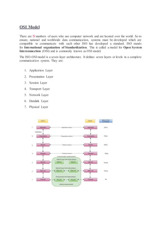
  • 1. OSI Model There are N numbers of users who use computer network and are located over the world. So to ensure, national and worldwide data communication, systems must be developed which are compatible to communicate with each other ISO has developed a standard. ISO stands for International organization of Standardization. This is called a model for Open System Interconnection (OSI) and is commonly known as OSI model. The ISO-OSI model is a seven layer architecture. It defines seven layers or levels in a complete communication system. They are: 1. Application Layer 2. Presentation Layer 3. Session Layer 4. Transport Layer 5. Network Layer 6. Datalink Layer 7. Physical Layer
  • 2. Feature of OSI Model 1. Big picture of communication over network is understandable through this OSI model. 2. We see how hardware and software work together. 3. We can understand new technologies as they are developed. 4. Troubleshooting is easier by separate networks. 5. Can be used to compare basic functional relationships on different networks. Principles of OSI Reference Model The OSI reference model has 7 layers. The principles that were applied to arrive at the seven layers can be briefly summarized as follows: 1. A layer should be created where a different abstraction is needed. 2. Each layer should perform a well-defined function. 3. The function of each layer should be chosen with an eye toward defining internationally standardized protocols. 4. The layer boundaries should be chosen to minimize the information flow across the interfaces. 5. The number of layers should be large enough that distinct functions need not be thrown together in the same layer out of necessity and small enough that architecture does not become unwieldly.
  • 3. Physical Layer The lowest layer of the OSI reference model is the physical layer. It is responsible for the actual physical connection between the devices. The physical layer contains information in the form of bits. It is responsible for transmitting individual bits from one node to the next. When receiving data, this layer will get the signal received and convert it into 0s and 1s and send them to the Data Link layer, which will put the frame back together. The functions of the physical layer are 1. Bit synchronization: The physical layer provides the synchronization of the bits by providing a clock. This clock controls both sender and receiver thus providing synchronization at bit level. 2. Bit rate control: The Physical layer also defines the transmission rate i.e. the number of bits sent per second. 3. Physical topologies: Physical layer specifies the way in which the different, devices/nodes are arranged in a network i.e. bus, star or mesh topolgy. 4. Transmission mode: Physical layer also defines the way in which the data flows between the two connected devices. The various transmission modes possible are: Simplex, half- duplex and full-duplex. * Hub, Repeater, Modem, Cables are Physical Layer devices. ** Network Layer, Data Link Layer and Physical Layer are also known as Lower Layers or Hardware Layers. Design Issues with Physical Layer  The Physical Layer is concerned with transmitting raw bits over a communication channel.  The design issue has to do with making sure that when one side sends a 1 bit, it is received by the other side as a 1 bit and not as a 0 bit.
  • 4.  Typical questions here are: o How many volts should be used to represent a 1 bit and how many for a 0? o How many nanoseconds a bit lasts? o Whether transmission may proceed simultaneously in both directions? o Whether transmission may proceed simultaneously in both directions? o How many pins the network connector has and what each pin is used for?  The design issues here largely deal with mechanical, electrical and timing interfaces, and the physical transmission medium, which lies below the physical layer. Data Link Layer  Data link layer synchronizes the information which is to be transmitted over the physical layer.  The main function of this layer is to make sure data transfer is error free from one node to another, over the physical layer.  Transmitting and receiving data frames sequentially is managed by this layer.  This layer sends and expects acknowledgements for frames received and sent respectively. Resending of non-acknowledgement received frames is also handled by this layer.  This layer establishes a logical layer between two nodes and also manages the Frame traffic control over the network. It signals the transmitting node to stop, when the frame buffers are full. The data link layer is responsible for the node to node delivery of the message. The main function of this layer is to make sure data transfer is error-free from one node to another, over the physical layer. When a packet arrives in a network, it is the responsibility of DLL to transmit it to the Host using its MAC address. Data Link Layer is divided into two sub layers :  Logical Link Control (LLC)  Media Access Control (MAC) The packet received from Network layer is further divided into frames depending on the frame size of NIC(Network Interface Card). DLL also encapsulates Sender and Receiver’s MAC address in the header The Receiver’s MAC address is obtained by placing an ARP(Address Resolution Protocol) request onto the wire asking “Who has that IP address?” and the destination host will reply with its MAC address.
  • 5. The functions of the data Link layer are : 1. Framing: Framing is a function of the data link layer. It provides a way for a sender to transmit a set of bits that are meaningful to the receiver. This can be accomplished by attaching special bit patterns to the beginning and end of the frame. 2. Physical addressing: After creating frames, Data link layer adds physical addresses (MAC address) of sender and/or receiver in the header of each frame. 3. Error control: Data link layer provides the mechanism of error control in which it detects and retransmits damaged or lost frames. 4. Flow Control: The data rate must be constant on both sides else the data may get corrupted thus , flow control coordinates that amount of data that can be sent before receiving acknowledgement. 5. Access control: When a single communication channel is shared by multiple devices, MAC sub-layer of data link layer helps to determine which device has control over the channel at a given time. Data-link layer uses some error control mechanism to ensure that frames (data bit streams) are transmitted with certain level of accuracy. But to understand how errors is controlled, it is essential to know what types of errors may occur. Types of Errors There may be three types of errors:  Single bit error In a frame, there is only one bit, anywhere though, which is corrupt.  Multiple bits error Frame is received with more than one bits in corrupted state.  Burst error
  • 6. Frame contains more than1 consecutive bits corrupted. Error control mechanism may involve two possible ways:  Error detection  Error correction Error Detection Errors in the received frames are detected by means of Parity Check and Cyclic Redundancy Check (CRC). In both cases, few extra bits are sent along with actual data to confirm that bits received at other end are same as they were sent. If the counter-check at receiver’ end fails, the bits are considered corrupted. Parity Check One extra bit is sent along with the original bits to make number of 1s either even in case of even parity, or odd in case of odd parity. The sender while creating a frame counts the number of 1s in it. For example, if even parity is used and number of 1s is even then one bit with value 0 is added. This way number of 1s remains even.If the number of 1s is odd, to make it even a bit with value 1 is added. The receiver simply counts the number of 1s in a frame. If the count of 1s is even and even parity is used, the frame is considered to be not-corrupted and is accepted. If the count of 1s is odd and odd parity is used, the frame is still not corrupted. If a single bit flips in transit, the receiver can detect it by counting the number of 1s. But when more than one bits are erro neous, then it is very hard for the receiver to detect the error. Cyclic Redundancy Check (CRC) CRC is a different approach to detect if the received frame contains valid data. This technique involves binary division of the data bits being sent. The divisor is generated using polynomials. The sender performs a division operation on the bits being sent and calculates the remainder. Before sending the actual bits, the sender adds the remainder at the end of the actual bits. Actual data bits plus the remainder is called a codeword. The sender transmits data bits as codewords.
  • 7. At the other end, the receiver performs division operation on codewords using the same CRC divisor. If the remainder contains all zeros the data bits are accepted, otherwise it is considered as there some data corruption occurred in transit. Error Correction In the digital world, error correction can be done in two ways:  Backward Error Correction When the receiver detects an error in the data received, it requests back the sender to retransmit the data unit.  Forward Error Correction When the receiver detects some error in the data received, it executes error-correcting code, which helps it to auto-recover and to correct some kinds of errors. The first one, Backward Error Correction, is simple and can only be efficiently used where retransmitting is not expensive. For example, fiber optics. But in case of wireless transmission retransmitting may cost too much. In the latter case, Forward Error Correction is used. To correct the error in data frame, the receiver must know exactly which bit in the frame is corrupted. To locate the bit in error, redundant bits are used as parity bits for error detection.For example, we take ASCII words (7 bits data), then there could be 8 kind of information we need: first seven bits to tell us which bit is error and one more bit to tell that there is no error. Data-link layer is responsible for implementation of point-to-point flow and error control mechanism. Flow Control When a data frame (Layer-2 data) is sent from one host to another over a single medium, it is required that the sender and receiver should work at the same speed. That is, sender sends at a speed on which the receiver can process and accept the data. What if the speed
  • 8. (hardware/software) of the sender or receiver differs? If sender is sending too fast the receiver may be overloaded, (swamped) and data may be lost. Two types of mechanisms can be deployed to control the flow:  Stop and Wait This flow control mechanism forces the sender after transmitting a data frame to stop and wait until the acknowledgement of the data-frame sent is received.  Sliding Window In this flow control mechanism, both sender and receiver agree on the number of data- frames after which the acknowledgement should be sent. As we learnt, stop and wait flow control mechanism wastes resources, this protocol tries to make use of underlying resources as much as possible. Error Control When data-frame is transmitted, there is a probability that data-frame may be lost in the transit or it is received corrupted. In both cases, the receiver does not receive the correct data-frame and sender does not know anything about any loss.In such case, both sender and receiver are equipped with some protocols which helps them to detect transit errors such as loss of data- frame. Hence, either the sender retransmits the data-frame or the receiver may request to resend the previous data-frame. Requirements for error control mechanism:  Error detection - The sender and receiver, either both or any, must ascertain that there is some error in the transit.  Positive ACK - When the receiver receives a correct frame, it should acknowledge it.  Negative ACK - When the receiver receives a damaged frame or a duplicate frame, it sends a NACK back to the sender and the sender must retransmit the correct frame.
  • 9.  Retransmission: The sender maintains a clock and sets a timeout period. If an acknowledgement of a data-frame previously transmitted does not arrive before the timeout the sender retransmits the frame, thinking that the frame or it’s acknowledgement is lost in transit. There are three types of techniques available which Data-link layer may deploy to control the errors by Automatic Repeat Requests (ARQ):  Stop-and-wait ARQ The following transition may occur in Stop-and-Wait ARQ: o The sender maintains a timeout counter. o When a frame is sent, the sender starts the timeout counter. o If acknowledgement of frame comes in time, the sender transmits the next frame in queue. o If acknowledgement does not come in time, the sender assumes that either the frame or its acknowledgement is lost in transit. Sender retransmits the frame and starts the timeout counter. o If a negative acknowledgement is received, the sender retransmits the frame.
  • 10.  Go-Back-N ARQ Stop and wait ARQ mechanism does not utilize the resources at their best.When the acknowledgement is received, the sender sits idle and does nothing. In Go-Back-N ARQ method, both sender and receiver maintain a window. The sending-window size enables the sender to send multiple frames without receiving the acknowledgement of the previous ones. The receiving-window enables the receiver to receive multiple frames and acknowledge them. The receiver keeps track of incoming frame’s sequence number. When the sender sends all the frames in window, it checks up to what sequence number it has received positive acknowledgement. If all frames are positively acknowledged, the sender sends next set of frames. If sender finds that it has received NACK or has not receive any ACK for a particular frame, it retransmits all the frames after which it does not receive any positive ACK.
  • 11.  Selective Repeat ARQ In Go-back-N ARQ, it is assumed that the receiver does not have any buffer space for its window size and has to process each frame as it comes. This enforces the sender to retransmit all the frames which are not acknowledged. In Selective-Repeat ARQ, the receiver while keeping track of sequence numbers, buffers the frames in memory and sends NACK for only frame which is missing or damaged. The sender in this case, sends only packet for which NACK is received. Network Layer 1. Network Layer routes the signal through different channels from one node to other. 2. It acts as a network controller. It manages the Subnet traffic. 3. It decides by which route data should take.
  • 12. 4. It divides the outgoing messages into packets and assembles the incoming packets into messages for higher levels. Network layer works for the transmission of data from one host to the other located in different networks. It also takes care of packet routing i.e. selection of the shortest path to transmit the packet, from the number of routes available. The sender & receiver’s IP address are placed in the header by the network layer. The functions of the Network layer are : 1. Routing: The network layer protocols determine which route is suitable from source to destination. This function of network layer is known as routing. 2. Logical Addressing: In order to identify each device on internetwork uniquely, network layer defines an addressing scheme. The sender & receiver’s IP address are placed in the header by network layer. Such an address distinguishes each device uniquely and universally. * Segment in Network layer is referred as Packet. ** Network layer is implemented by networking devices such as routers. Devices which work on Network Layer mainly focus on routing. Routing may include various tasks aimed to achieve a single goal. These can be:  Addressing devices and networks.  Populating routing tables or static routes.  Queuing incoming and outgoing data and then forwarding them according to quality of service constraints set for those packets.  Internetworking between two different subnets.  Delivering packets to destination with best efforts.  Provides connection oriented and connection less mechanism. Network Layer Features With its standard functionalities, Layer 3 can provide various features as:  Quality of service management  Load balancing and link management  Security  Interrelation of different protocols and subnets with different schema.  Different logical network design over the physical network design.  L3 VPN and tunnels can be used to provide end to end dedicated connectivity. Internet protocol is widely respected and deployed Network Layer protocol which helps to communicate end to end devices over the internet. It comes in two flavors. IPv4 which has ruled the world for decades but now is running out of address space. IPv6 is created to replace IPv4 and hopefully mitigates limitations of IPv4 too.
  • 13. Layer 3 network addressing is one of the major tasks of Network Layer. Network Addresses are always logical i.e. these are software based addresses which can be changed by appropriate configurations. A network address always points to host / node / server or it can represent a whole network. Network address is always configured on network interface card and is generally mapped by system with the MAC address (hardware address or layer-2 address) of the machine for Layer- 2 communication. There are different kinds of network addresses in existence:  IP  IPX  AppleTalk We are discussing IP here as it is the only one we use in practice these days. IP addressing provides mechanism to differentiate between hosts and network. Because IP addresses are assigned in hierarchical manner, a host always resides under a specific network.The host which needs to communicate outside its subnet, needs to know destination network address, where the packet/data is to be sent. Hosts in different subnet need a mechanism to locate each other. This task can be done by DNS. DNS is a server which provides Layer-3 address of remote host mapped with its domain name or FQDN. When a host acquires the Layer-3 Address (IP Address) of the remote host, it forwards all its packet to its gateway. A gateway is a router equipped with all the information which leads to route packets to the destination host. Routers take help of routing tables, which has the following information:
  • 14.  Method to reach the network Routers upon receiving a forwarding request, forwards packet to its next hop (adjacent router) towards the destination. The next router on the path follows the same thing and eventually the data packet reaches its destination. Network address can be of one of the following:  Unicast (destined to one host)  Multicast (destined to group)  Broadcast (destined to all)  Anycast (destined to nearest one) A router never forwards broadcast traffic by default. Multicast traffic uses special treatment as it is most a video stream or audio with highest priority. Anycast is just similar to unicast, except that the packets are delivered to the nearest destination when multiple destinations are available. When a device has multiple paths to reach a destination, it always selects one path by preferring it over others. This selection process is termed as Routing. Routing is done by special network devices called routers or it can be done by means of software processes.The software based routers have limited functionality and limited scope. A router is always configured with some default route. A default route tells the router where to forward a packet if there is no route found for specific destination. In case there are multiple path existing to reach the same destination, router can make decision based on the following information:  Hop Count  Bandwidth  Metric  Prefix-length  Delay Routes can be statically configured or dynamically learnt. One route can be configured to be preferred over others. Unicast routing Most of the traffic on the internet and intranets known as unicast data or unicast traffic is sent with specified destination. Routing unicast data over the internet is called unicast routing. It is the simplest form of routing because the destination is already known. Hence the router just has to look up the routing table and forward the packet to next hop.
  • 15. Broadcast routing By default, the broadcast packets are not routed and forwarded by the routers on any network. Routers create broadcast domains. But it can be configured to forward broadcasts in some special cases. A broadcast message is destined to all network devices. Broadcast routing can be done in two ways (algorithm):  A router creates a data packet and then sends it to each host one by one. In this case, the router creates multiple copies of single data packet with different destination addresses. All packets are sent as unicast but because they are sent to all, it simulates as if router is broadcasting. This method consumes lots of bandwidth and router must destination address of each node.  Secondly, when router receives a packet that is to be broadcasted, it simply floods those packets out of all interfaces. All routers are configured in the same way.
  • 16. This method is easy on router's CPU but may cause the problem of duplicate packets received from peer routers. Reverse path forwarding is a technique, in which router knows in advance about its predecessor from where it should receive broadcast. This technique is used to detect and discard duplicates. Multicast Routing Multicast routing is special case of broadcast routing with significance difference and challenges. In broadcast routing, packets are sent to all nodes even if they do not want it. But in Multicast routing, the data is sent to only nodes which wants to receive the packets. The router must know that there are nodes, which wish to receive multicast packets (or stream) then only it should forward. Multicast routing works spanning tree protocol to avoid looping. Multicast routing also uses reverse path Forwarding technique, to detect and discard duplicates and loops. Anycast Routing Anycast packet forwarding is a mechanism where multiple hosts can have same logical address. When a packet destined to this logical address is received, it is sent to the host which is nearest in routing topology.
  • 17. Anycast routing is done with help of DNS server. Whenever an Anycast packet is received it is enquired with DNS to where to send it. DNS provides the IP address which is the nearest IP configured on it. Unicast Routing Protocols There are two kinds of routing protocols available to route unicast packets:  Distance Vector Routing Protocol Distance Vector is simple routing protocol which takes routing decision on the number of hops between source and destination. A route with less number of hops is considered as the best route. Every router advertises its set best routes to other routers. Ultimately, all routers build up their network topology based on the advertisements of their peer routers, For example Routing Information Protocol (RIP).  Link State Routing Protocol Link State protocol is slightly complicated protocol than Distance Vector. It takes into account the states of links of all the routers in a network. This technique helps routes build a common graph of the entire network. All routers then calculate their best path for routing purposes.for example, Open Shortest Path First (OSPF) and Intermediate System to Intermediate System (ISIS). Multicast Routing Protocols Unicast routing protocols use graphs while Multicast routing protocols use trees, i.e. spanning tree to avoid loops. The optimal tree is called shortest path spanning tree.  DVMRP - Distance Vector Multicast Routing Protocol  MOSPF - Multicast Open Shortest Path First  CBT - Core Based Tree
  • 18.  PIM - Protocol independent Multicast Protocol Independent Multicast is commonly used now. It has two flavors:  PIM Dense Mode This mode uses source-based trees. It is used in dense environment such as LAN.  PIM Sparse Mode This mode uses shared trees. It is used in sparse environment such as WAN. Routing Algorithms The routing algorithms are as follows: Flooding Flooding is simplest method packet forwarding. When a packet is received, the routers send it to all the interfaces except the one on which it was received. This creates too much burden on the network and lots of duplicate packets wandering in the network. Time to Live (TTL) can be used to avoid infinite looping of packets. There exists another approach for flooding, which is called Selective Flooding to reduce the overhead on the network. In this method, the router does not flood out on all the interfaces, but selective ones. Shortest Path Routing decision in networks, are mostly taken on the basis of cost between source and destination. Hop count plays major role here. Shortest path is a technique which uses various algorithms to decide a path with minimum number of hops. Common shortest path algorithms are:  Dijkstra's algorithm  Bellman Ford algorithm  Floyd Warshall algorithm  In real world scenario, networks under same administration are generally scattered geographically. There may exist requirement of connecting two different networks of same kind as well as of different kinds. Routing between two networks is called internetworking.  Networks can be considered different based on various parameters such as, Protocol, topology, Layer-2 network and addressing scheme.  In internetworking, routers have knowledge of each other’s address and addresses beyond them. They can be statically configured go on different network or they can learn by using internetworking routing protocol.
  • 19.   Routing protocols which are used within an organization or administration are called Interior Gateway Protocols or IGP. RIP, OSPF are examples of IGP. Routing between different organizations or administrations may have Exterior Gateway Protocol, and there is only one EGP i.e. Border Gateway Protocol. Tunneling  If they are two geographically separate networks, which want to communicate with each other, they may deploy a dedicated line between or they have to pass their data through intermediate networks.  Tunneling is a mechanism by which two or more same networks communicate with each other, by passing intermediate networking complexities. Tunneling is configured at both ends.   When the data enters from one end of Tunnel, it is tagged. This tagged data is then routed inside the intermediate or transit network to reach the other end of Tunnel. When data exists the Tunnel its tag is removed and delivered to the other part of the network.
  • 20.  Both ends seem as if they are directly connected and tagging makes data travel through transit network without any modifications. Packet Fragmentation  Most Ethernet segments have their maximum transmission unit (MTU) fixed to 1500 bytes. A data packet can have more or less packet length depending upon the application. Devices in the transit path also have their hardware and software capabilities which tell what amount of data that device can handle and what size of packet it can process.  If the data packet size is less than or equal to the size of packet the transit network can handle, it is processed neutrally. If the packet is larger, it is broken into smaller pieces and then forwarded. This is called packet fragmentation. Each fragment contains the same destination and source address and routed through transit path easily. At the receiving end it is assembled again.  If a packet with DF (don’t fragment) bit set to 1 comes to a router which can not handle the packet because of its length, the packet is dropped.  When a packet is received by a router has its MF (more fragments) bit set to 1, the router then knows that it is a fragmented packet and parts of the original packet is on the way.  If packet is fragmented too small, the overhead is increases. If the packet is fragmented too large, intermediate router may not be able to process it and it might get dropped. Transport Layer Transport layer provides services to application layer and takes services from network layer. The data in the transport layer is referred to as Segments. It is responsible for the End to End Delivery of the complete message. The transport layer also provides the acknowledgement of the successful data transmission and re-transmits the data if an error is found. Sender Side: Transport layer receives the formatted data from the upper layers, performs Segmentation and also implements Flow & Error control to ensure proper data transmission. It also adds Source and Destination port number in its header and forwards the segmented data to the network Layer Note: The sender need to know the port number associated with the receiver’s application. Generally, this destination port number is configured, either by default or manually. For example, when a web application makes a request to a web server, it typically uses port number 80, because this is the default port assigned to web applications. Many applications have default port assigned Receiver Side Transport Layer reads the port number from its header and forwards the Data which it has received to the respective application. It also performs sequencing and reassembling of the segmented data. The functions of the transport layer are : 1. Segmentation and Reassembly: This layer accepts the message from the (session) layer , breaks the message into smaller units . Each of the segment produced has a header associated with it. The transport layer at the destination station reassembles the message.
  • 21. 2. Service Point Addressing: In order to deliver the message to correct process, transport layer header includes a type of address called service point address or port address. Thus by specifying this address, transport layer makes sure that the message is delivered to the correct process. The services provided by the transport layer : 1. Connection Oriented Service: It is a three-phase process which include ConnectionEstablishment DataTransfer Terminationdisconnection In this type of transmission, the receiving device sends an acknowledgement, back to the source after a packet or group of packet is received. This type of transmission is reliable and secure. 2. Connection less service: It is a one-phase process and includes Data Transfer. In this type of transmission, the receiver does not acknowledge receipt of a packet. This approach allows for much faster communication between devices. Connection-oriented service is more reliable than connectionless Service. Data in the Transport Layer is called as Segments. Transport layer is operated by the Operating System. It is a part of the OS and communicates with the Application Layer by making system calls. Transport Layer is called as Heart of OSI model. Next Layer in OSI Model is recognized as Transport Layer (Layer-4). All modules and procedures pertaining to transportation of data or data stream are categorized into this layer. As all other layers, this layer communicates with its peer Transport layer of the remote host. Transport layer offers peer-to-peer and end-to-end connection between two processes on remote hosts. Transport layer takes data from upper layer (i.e. Application layer) and then breaks it into smaller size segments, numbers each byte, and hands over to lower layer (Network Layer) for delivery. Functions  This Layer is the first one which breaks the information data, supplied by Application layer in to smaller units called segments. It numbers every byte in the segment and maintains their accounting.  This layer ensures that data must be received in the same sequence in which it was sent.  This layer provides end-to-end delivery of data between hosts which may or may not belong to the same subnet.  All server processes intend to communicate over the network are equipped with well- known Transport Service Access Points (TSAPs) also known as port numbers. End-to-End Communication A process on one host identifies its peer host on remote network by means of TSAPs, also known as Port numbers. TSAPs are very well defined and a process which is trying to communicate with its peer knows this in advance.
  • 22. For example, when a DHCP client wants to communicate with remote DHCP server, it always requests on port number 67. When a DNS client wants to communicate with remote DNS server, it always requests on port number 53 (UDP). The two main Transport layer protocols are:  Transmission Control Protocol It provides reliable communication between two hosts.  User Datagram Protocol It provides unreliable communication between two hosts. The transmission Control Protocol (TCP) is one of the most important protocols of Internet Protocols suite. It is most widely used protocol for data transmission in communication network such as internet. Features  TCP is reliable protocol. That is, the receiver always sends either positive or negative acknowledgement about the data packet to the sender, so that the sender always has bright clue about whether the data packet is reached the destination or it needs to resend it.  TCP ensures that the data reaches intended destination in the same order it was sent.  TCP is connection oriented. TCP requires that connection between two remote points be established before sending actual data.  TCP provides error-checking and recovery mechanism.  TCP provides end-to-end communication.  TCP provides flow control and quality of service.  TCP operates in Client/Server point-to-point mode.  TCP provides full duplex server, i.e. it can perform roles of both receiver and sender.
  • 23. Header The length of TCP header is minimum 20 bytes long and maximum 60 bytes.  Source Port (16-bits) - It identifies source port of the application process on the sending device.  Destination Port (16-bits) - It identifies destination port of the application process on the receiving device.  Sequence Number (32-bits) - Sequence number of data bytes of a segment in a session.  Acknowledgement Number (32-bits) - When ACK flag is set, this number contains the next sequence number of the data byte expected and works as acknowledgement of the previous data received.  Data Offset (4-bits) - This field implies both, the size of TCP header (32-bit words) and the offset of data in current packet in the whole TCP segment.  Reserved (3-bits) - Reserved for future use and all are set zero by default.  Flags (1-bit each) o NS - Nonce Sum bit is used by Explicit Congestion Notification signaling process. o CWR - When a host receives packet with ECE bit set, it sets Congestion Windows Reduced to acknowledge that ECE received. o ECE -It has two meanings:  If SYN bit is clear to 0, then ECE means that the IP packet has its CE (congestion experience) bit set.  If SYN bit is set to 1, ECE means that the device is ECT capable. o URG - It indicates that Urgent Pointer field has significant data and should be processed. o ACK - It indicates that Acknowledgement field has significance. If ACK is cleared to 0, it indicates that packet does not contain any acknowledgement. o PSH - When set, it is a request to the receiving station to PUSH data (as soon as it comes) to the receiving application without buffering it.
  • 24. o RST - Reset flag has the following features:  It is used to refuse an incoming connection.  It is used to reject a segment.  It is used to restart a connection. o SYN - This flag is used to set up a connection between hosts. o FIN - This flag is used to release a connection and no more data is exchanged thereafter. Because packets with SYN and FIN flags have sequence numbers, they are processed in correct order.  Windows Size - This field is used for flow control between two stations and indicates the amount of buffer (in bytes) the receiver has allocated for a segment, i.e. how much data is the receiver expecting.  Checksum - This field contains the checksum of Header, Data and Pseudo Headers.  Urgent Pointer - It points to the urgent data byte if URG flag is set to 1.  Options - It facilitates additional options which are not covered by the regular header. Option field is always described in 32-bit words. If this field contains data less than 32-bit, padding is used to cover the remaining bits to reach 32-bit boundary. Addressing TCP communication between two remote hosts is done by means of port numbers (TSAPs). Ports numbers can range from 0 – 65535 which are divided as:  System Ports (0 – 1023)  User Ports ( 1024 – 49151)  Private/Dynamic Ports (49152 – 65535) Connection Management TCP communication works in Server/Client model. The client initiates the connection and the server either accepts or rejects it. Three-way handshaking is used for connection management.
  • 25. Establishment Client initiates the connection and sends the segment with a Sequence number. Server acknowledges it back with its own Sequence number and ACK of client’s segment which is one more than client’s Sequence number. Client after receiving ACK of its segment sends an acknowledgement of Server’s response. Release Either of server and client can send TCP segment with FIN flag set to 1. When the receiving end responds it back by ACKnowledging FIN, that direction of TCP communication is closed and connection is released. Bandwidth Management TCP uses the concept of window size to accommodate the need of Bandwidth management. Window size tells the sender at the remote end, the number of data byte segments the receiver at this end can receive. TCP uses slow start phase by using window size 1 and increases the window size exponentially after each successful communication. For example, the client uses windows size 2 and sends 2 bytes of data. When the acknowledgement of this segment received the windows size is doubled to 4 and next sent the segment sent will be 4 data bytes long. When the acknowledgement of 4-byte data segment is received, the client sets windows size to 8 and so on. If an acknowledgement is missed, i.e. data lost in transit network or it received NACK, then the window size is reduced to half and slow start phase starts again. Error Control &and Flow Control TCP uses port numbers to know what application process it needs to handover the data segment. Along with that, it uses sequence numbers to synchronize itself with the remote host. All data segments are sent and received with sequence numbers. The Sender knows which last data segment was received by the Receiver when it gets ACK. The Receiver knows about the last segment sent by the Sender by referring to the sequence number of recently received packet. If the sequence number of a segment recently received does not match with the sequence number the receiver was expecting, then it is discarded and NACK is sent back. If two segments arrive with the same sequence number, the TCP timestamp value is compared to make a decision. Multiplexing The technique to combine two or more data streams in one session is called Multiplexing. When a TCP client initializes a connection with Server, it always refers to a well-defined port number which indicates the application process. The client itself uses a randomly generated port number from private port number pools. Using TCP Multiplexing, a client can communicate with a number of different application process in a single session. For example, a client requests a web page which in turn contains different types of data (HTTP, SMTP, FTP etc.) the TCP session timeout is increased and the session is kept open for longer time so that the three-way handshake overhead can be avoided.
  • 26. This enables the client system to receive multiple connection over single virtual connection. These virtual connections are not good for Servers if the timeout is too long. Congestion Control When large amount of data is fed to system which is not capable of handling it, congestion occurs. TCP controls congestion by means of Window mechanism. TCP sets a window size telling the other end how much data segment to send. TCP may use three algorithms for congestion control:  Additive increase, Multiplicative Decrease  Slow Start  Timeout React Session Layer This layer is responsible for establishment of connection, maintenance of sessions, authentication and also ensures security. The functions of the session layer are : 1. Session establishment, maintenance and termination: The layer allows the two processes to establish, use and terminate a connection. 2. Synchronization : This layer allows a process to add checkpoints which are considered as synchronization points into the data. These synchronization point help to identify the error so that the data is re-synchronized properly, and ends of the messages are not cut prematurely and data loss is avoided. 3. Dialog Controller : The session layer allows two systems to start communication with each other in half-duplex or full-duplex. 4. Session Layer manages and synchronize the conversation between two different applications. 5. Transfer of data from source to destination session layer streams of data are marked and are resynchronized properly, so that the ends of the messages are not cut prematurely and data loss is avoided. Timer Management TCP uses different types of timer to control and management various tasks: Keep-alive timer:  This timer is used to check the integrity and validity of a connection.  When keep-alive time expires, the host sends a probe to check if the connection still exists. Retransmission timer:
  • 27.  This timer maintains stateful session of data sent.  If the acknowledgement of sent data does not receive within the Retransmission time, the data segment is sent again. Persist timer:  TCP session can be paused by either host by sending Window Size 0.  To resume the session a host needs to send Window Size with some larger value.  If this segment never reaches the other end, both ends may wait for each other for infinite time.  When the Persist timer expires, the host re-sends its window size to let the other end know.  Persist Timer helps avoid deadlocks in communication. Timed-Wait:  After releasing a connection, either of the hosts waits for a Timed-Wait time to terminate the connection completely.  This is in order to make sure that the other end has received the acknowledgement of its connection termination request.  Timed-out can be a maximum of 240 seconds (4 minutes). Presentation Layer : Presentation layer is also called the Translation layer.The data from the application layer is extracted here and manipulated as per the required format to transmit over the network. The functions of the presentation layer are : 1. Translation : For example, ASCII to EBCDIC. 2. Encryption/ Decryption : Data encryption translates the data into another form or code. The encrypted data is known as the cipher text and the decrypted data is known as plain text. A key value is used for encrypting as well as decrypting data. 3. Compression: Reduces the number of bits that need to be transmitted on the network. Functions of Presentation Layer 1. Translation: Before being transmitted, information in the form of characters and numbers should be changed to bit streams. The presentation layer is responsible for interoperability between encoding methods as different computers use different encoding methods. It translates data between the formats the network requires and the format the computer.
  • 28. 2. Encryption: It carries out encryption at the transmitter and decryption at the receiver. 3. Compression: It carries out data compression to reduce the bandwidth of the data to be transmitted. The primary role of Data compression is to reduce the number of bits to be 0transmitted. It is important in transmitting multimedia such as audio, video, text etc. Design Issues with Presentation Layer  To manage and maintain the Syntax and Semantics of the information transmitted.  Encoding data in a standard agreed upon way. Eg: String, double, date, etc.  Perform Standard Encoding on wire. 
  • 29. Application Layer : At the very top of the OSI Reference Model stack of layers, we find Application layer which is implemented by the network applications. These applications produce the data, which has to be transferred over the network. This layer also serves as a window for the application services to access the network and for displaying the received information to the user. The functions of the Application layer are : 1. Network Virtual Terminal 2. FTAM-File transfer access and management 3. Mail Services 4. Directory Services OSI model acts as a reference model and is not implemented in the Internet because of its late invention. Current model being used is the TCP/IP model. The application layer is the highest abstraction layer of the TCP/IP model that provides the interfaces and protocols needed by the users. It combines the functionalities of the session layer, the presentation layer and the application layer of the OSI model. The functions of the application layer are −  It facilitates the user to use the services of the network.  It is used to develop network-based applications.  It provides user services like user login, naming network devices, formatting messages, and e-mails, transfer of files etc.  It is also concerned with error handling and recovery of the message as a whole. This layer uses a number of protocols, the main among which are as follows −  Hyper Text Transfer Protocol, HTTP − It is the underlying protocol for world wide web. It defines how hypermedia messages are formatted and transmitted.  File Transfer Protocol, FTP − It is a client-server based protocol for transfer of files between client and server over the network.  Simple Mail Transfer Protocol, SMTP − It lays down the rules and semantics for sending and receiving electronic mails (e-mails).  Domain NameSystem, DNS − It is a naming system for devices in networks. It provides services for translating domain names to IP addresses.  TELNET− It provides bi-directional text-oriented services for remote login to the hosts over the network.  Simple Network Management Protocol, SNMP − It is for managing, monitoring the network and for organizing information about the networked devices. The following diagram shows the transport layer in the TCP/IP protocol suite −
  • 30. It is the top most layer of OSI Model. Manipulation of data(information) in various ways is done in this layer which enables user or software to get access to the network. Some services provided by this layer includes: E-Mail, transferring files, distributing the results to user, directory services, network resources, etc. The Application Layer contains a variety of protocols that are commonly needed by users. One widely-used application protocol is HTTP(HyperText Transfer Protocol), which is the basis for the World Wide Web. When a browser wants a web page, it sends the name of the page it wants to the server using HTTP. The server then sends the page back. Other Application protocols that are used are: File Transfer Protocol(FTP), Trivial File Transfer Protocol(TFTP), Simple Mail Transfer Protocol(SMTP), TELNET, Domain Name System(DNS) etc. Functions of Application Layer 1. Mail Services: This layer provides the basis for E-mail forwarding and storage. 2. Network Virtual Terminal: It allows a user to log on to a remote host. The application creates software emulation of a terminal at the remote host. User's computer talks to the software terminal which in turn talks to the host and vice versa. Then the remote host believes it is communicating with one of its own terminals and allows user to log on. 3. Directory Services: This layer provides access for global information about various services. 4. File Transfer, Access and Management (FTAM): It is a standard mechanism to access files and manages it. Users can access files in a remote computer and manage it. They can also retrieve files from a remote computer.
  • 31. Design Issues with Application Layer There are commonly reoccurring problems that occur in the design and implementation of Application Layer protocols and can be addressed by patterns from several different pattern languages:  Pattern Language for Application-level Communication Protocols  Service Design Patterns  Patterns of Enterprise Application Architecture  Pattern-Oriented Software Architecture