Logic gates
•
1 like•369 views

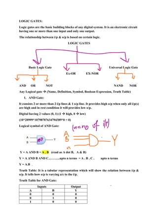
Basic Gates (AND, OR, NOT) Universal Gates (NAND, NOR) EX-OR, EX-NOR

Recommended
Recommended
More Related Content
What's hot
What's hot (20)
Similar to Logic gates
Similar to Logic gates (20)
More from Sweta Kumari Barnwal
More from Sweta Kumari Barnwal (20)
Recently uploaded
Recently uploaded (20)
Logic gates
- 1. LOGIC GATES: Logic gates are the basic building blocks of any digital system. It is an electronic circuit having one or more than one input and only one output. The relationship between i/p & o/p is based on certain logic. LOGIC GATES Basic Logic Gate Universal Logic Gate Ex-OR EX-NOR AND OR NOT NAND NOR Any Logical gate → (Name, Definition, Symbol, Boolean Expression, Truth Table) 1. AND Gate: It consists 2 or more than 2 i/p lines & 1 o/p line. It provides high o/p when only all i/p(s) are high and in rest condition it will provides low o/p. Digital having 2 values (0, 1) (1 → high, 0 → low) (10*20999*10798787634794389*0 = 0) Logical symbol of AND Gate: Y = A AND B = A . B (read as A dot B, A & B) Y = A AND B AND C………..upto n terms = A . B . C . upto n terms Y = A.B Truth Table: It is a tabular representation which will show the relation between i/p & o/p. It tells how o/p is varying a/c to the i/p. Truth Table for AND Gate: Inputs Output A B Y 0 0 0 0 1 0 1 0 0
- 2. 1 1 1 1.1.1.1..1.1.1.1..1…………1…………….1 = 1 2. OR GATE: It consists 2 or more than 2 i/p lines & 1 o/p line. It provides low o/p when only all i/p(s) are low and in rest condition it will provides high o/p. Y = A OR B = A+B (OR → +) Y = A OR B OR C OR up to n terms ( A+B+C+ up to n terms) Inputs Output A B Y 0 0 0 0 1 1 1 0 1 1 1 1 Y = A+B+C+D……………up to 100 terms 3. NOT GATE: (Inverter) (Complement) It consists 1 i/p line & 1 o/p line. It provides low o/p when i/p is high & vice versa. Y = A’ = NOT (A) = A I/P (A) O/P (B) 0 1 1 0
- 3. 4. NAND GATE: (NOT + AND) Reverse of AND GATE, Compliment of AND GATE, Inverted AND GATE Y = A AND B = A NAND B = A NOT AND B = A.B = (A.B)’ Truth Table of NAND GATE: Inputs AND Output NAND O/P A B Y1 Y 0 0 0 1 0 1 0 1 1 0 0 1 1 1 1 0 NAND: It consists 2 or more than 2 i/p lines & 1 o/p line. It provides low o/p when only all i/p(s) are high and in rest condition it will provides low o/p. 5. NOR GATES: (NOT + OR) Reverse of OR GATE, Compliment of OR GATE, Inverted OR GATE
- 4. Inputs Intermediate Output Output A B Y1 = A+B Y = (A+B)’ 0 0 0 1 0 1 1 0 1 0 1 0 1 1 1 0 NOR: It consists 2 or more than 2 i/p lines & 1 o/p line. It provides high o/p when only all i/p(s) are low and in rest condition it will provides low o/p.
- 5. EX-OR Gate (XOR Gate): Special type of gate, used for adder & subtractor. Exclusive - OR Gate/X-OR Gate. It consists 2 or more than 2 i/p lines & 1 o/p line. It provides high o/p, when only all inputs are different. Y = A XOR B Y = A’B + AB’ Inputs Output A B Y 0 0 0 0 1 1 1 0 1 1 1 0 EX-NOR Gate (XNOR Gate): Special type of gate, used for adder & subtractor. Exclusive N-OR Gate/X-NOR Gate. It consists 2 or more than 2 i/p lines & 1 o/p line. It provides high o/p, when only all inputs are same. Inputs Output A B Y 0 0 1 0 1 0 1 0 0 1 1 1
- 7. AND → Y = A.B NAND → Y = (A.B)’ OR → Y= A+B N OR → Y = (A+B)’ NOT → Y = A’ Buffer → Y = A XOR → Y = A ⊕ B XNOR → Y = (A ⊕ B)’ Q. What is Logic Gates? Classify & explain with their symbols, Boolean equations & truth table. Q. Why NAND & NOR Gates are called Universal Gates? NAND & NOR Gates are called Universal Gates because Combinations of NAND/NOR can be used to work as of the basic gates (AND, OR & NOT). a) NAND Gate as a NOT Gate: A a b Y 0 0 0 1 1 1 1 0 b) NAND as an AND Gate
- 8. (NAND = AND+NOT) → (AND = NAND - NOT) (NAND = NOT + AND) (AND = NAND + NOT) A B Y1 Y 0 0 1 0 0 1 1 0 1 0 1 0 1 1 0 1 c) NAND as an OR Gate A B Y1 Y2 Y 0 0 0 1 1 0 1 1 NAND → NOT (1 NAND gate required)
- 9. NAND → AND (2 NAND gates required) NAND → OR (3 NAND gates required) a) NOR as a NOT Gate A a b Y 0 0 0 1 1 1 1 0 b) NOR as an OR Gate A B Y1 Y 0 0 1 0 0 1 0 1 1 0 0 1 1 1 0 1 c) NOR as an AND Gate A B Y1 Y2 Y 0 0 1 1 0 0 1 1 0 0 1 0 0 1 0 1 1 0 0 1