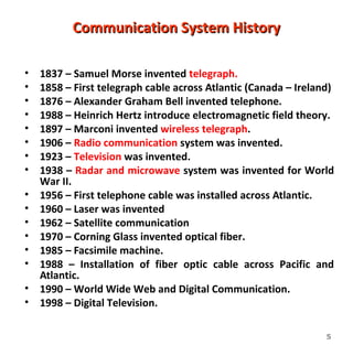
INTRODUCTION TO
ANALOG COMMUNICATIONS
1
Course objective
At the end of the semester, the learner
will be able to:
• Explain the principles of a
communication systems
• Discuss the nature of information,
different types of signals involved and
their characteristics
• Determine the need of modulation and
differentiate various type of modulation
techniques
2
3
“How do you want to send
data/information to someone
who is far from you?”
COMMUNICATION OVER LONG DISTANCES IS NO LONGER A PROBLEM.
4
Communication : To transfer information from one
place to another
Communication System HistoryCommunication System History
• 1837 – Samuel Morse invented telegraph.
• 1858 – First telegraph cable across Atlantic (Canada – Ireland)
• 1876 – Alexander Graham Bell invented telephone.
• 1988 – Heinrich Hertz introduce electromagnetic field theory.
• 1897 – Marconi invented wireless telegraph.
• 1906 – Radio communication system was invented.
• 1923 – Television was invented.
• 1938 – Radar and microwave system was invented for World
War II.
• 1956 – First telephone cable was installed across Atlantic.
• 1960 – Laser was invented
• 1962 – Satellite communication
• 1970 – Corning Glass invented optical fiber.
• 1985 – Facsimile machine.
• 1988 – Installation of fiber optic cable across Pacific and
Atlantic.
• 1990 – World Wide Web and Digital Communication.
• 1998 – Digital Television.
5
• The words "tele", "phon", and "graph" are derived from Greek.
– Tele – means ‘at a distance’
– Phon – means sound or speech
– Graph - means writing or drawing
• Therefore, telecommunication means communication at a distance. This can be
done through wires called transmission lines or through atmosphere by a radio
link. Other examples include:
– Telephone – speaking at a distance
Television – seeing at a distance
Telegraph – writing at a distance
6
7
Basic Communication SystemBasic Communication System
Transmitter
Transmission
Medium Receiver
Input
Transducer
Output
Transducer
Noise
wired / wireless
mtx(t)
s(t) r(t)
ptx(t)
n(t)
mrx(t)prx(t)
s(t) – Input signal; audio, video, image, data etc.
mtx(t) – Modulating signal; input signal that has been converted to electrical signal.
ptx(t) – Modulated signal transmit by the transmitter.
n(t) – Noise signal.
prx(t) – Modulated signal receive by the receiver.
mrx(t) – Modulating signal at the receiver.
r(t) – Output signal.
8
• Input Transducer – convert input signal, s(t) in electrical forms. eg:
microphone.
• Transmitter – involve modulation process – convert modulating signal, mtx(t)
to modulated signal, ptx(t). And finally transmit the signal.
• Transmission medium – connecting the transmitter and the receiver that
enable the modulated signal, ptx(t) propagate through the medium.
• Receiver – receive the modulated signal, prx(t) and then convert the signal to
modulating signal, mrx(t) through the process called demodulation.
• Output Transducer – convert the modulating signal, mrx(t) to its original forms
(output signal), r(t) that is useful to the users. eg: loud speaker.
Component Function in BasicComponent Function in Basic
Communication SystemCommunication System
9
Transmission Medium (Guided)Transmission Medium (Guided)
Twisted pair
– Unshielded Twisted Pair (UTP)
– Shielded Twisted Pair (STP)
Coaxial
Fiber Optic
Waveguide
Coaxial Cable
•First type of
networking media
used
•Available in
different types (RG-
6 – Cable TV,
RG58/U – Thin
Ethernet, RG8 –
Thick Ethernet
•Largely replaced by
twisted pair for
networks
Unshielded Twisted Pair
Advantages
Inexpensive
Easy to terminate
Widely used, tested
Supports many
network types
 Disadvantages
Susceptible to
interference
Prone to damage
during installation
Distance
limitations not
understood or
followed
Glass Media
• Core of silica, extruded glass or plastic
• Single-mode is 0.06 of a micron in diameter
• Multimode = 0.5 microns
• Cladding can be Kevlar, fibreglass or even steel
• Outer coating made from fire-proof plastic
 Advantages
 Can be installed over long distances
 Provides large amounts of
bandwidth
 Not susceptible to EMI RFI
 Can not be easily tapped (secure)
 Disadvantages
 Most expensive media
to purchase and install
 Rigorous guidelines for
installation
Wireless
CHAPTER 1
INTRODUCTION TO COMMUNICATION SYSTEMS
WHAT IS BASEBAND ?
Data
(nonelectrical)
Electrical
Waveform
Without any shift in the range of frequencies of the signal
The signal is in its
original form, not changed by modulation.
Baseband is the original information that is to be Sent.
Modulation
Continuous wave Pulse
PAM
PPM
PWM
PCM
Digital Analog
ASK
FSK
PSK,
etc
Linear Exponential
AM
DSB-
SC
SSB
VSB
FM
PM
Based on
the type of
carrier
wave
Based on
the type of
modulating
signal
Based on the
relationship
between
modulating
and
modulated
signal
TYPE OF MODULATION
 Amplitude Modulation (AM)
 Frequency Modulation (FM)
 Phase Modulation (PM)
16
TYPE OF MODULATION
17
ANALOG AND DIGITAL SIGNAL
 The information can be in term of :
 Analog form such as Human Voice or Music
 Digital form such as binary-coded number.
 There are 2 basic type of communication :
 Analog Communication
 Digital Communication
18
Chapter 1
Introduction to Communication Systems
Example of Analog signal is shown
below:
 Analog comes in term of Sinusoid
(Sine or Cosine wave)
 Analog signals are continuous
electrical signals that vary in
19
Analog Signals
• Human Voice – best example
• Ear recognises sounds 20KHz or less
• AM Radio – 535KHz to 1605KHz
• FM Radio – 88MHz to 108MHz
Chapter 1
Introduction to Communication Systems
 Example of Digital Signal is shown below:
21
Digital signals
• Represented by Square Wave
• All data represented by binary values
• Single Binary Digit – Bit
• Transmission of contiguous group of bits is a
bit stream
• Not all decimal values can be represented by
binary
1 0 1 0 1 0 1 0
Analog or Digital
• Analog Message: continuous in amplitude and
over time
– AM, FM for voice sound
– Traditional TV for analog video
– First generation cellular phone (analog mode)
– Record player
• Digital message: 0 or 1, or discrete value
– VCD, DVD
– 2G/3G cellular phone
– Data on your disk
– Your grade
• Digital age: why digital communication will
prevail
Chapter 1
Introduction to Communication Systems
WHAT IS FREQUENCY SPECTRUM ?
IT CONSISTS OF ALL FREQUENCIES CONTAINED IN THE
WAVEFORM AND THEIR RESPECTIVE AMPLITUDE IN
THE FREQUENCY DOMAIN.
24
The Bands
VLF LF MF HF VHF UHF SHF EHF
Submillimeter
Range
ELF
3MHz 30MHz300MHz 3GHz 30GHz 300GHz
Far
Infra-
Red
300KHz30KHz 3THz
Radio Optical
3KHz
Near
Infra-
Red
700nm
1PetaHz
R
e
d
O
r
a
n
g
e
Y
e
l
l
o
w
G
r
e
e
n
B
l
u
e
I
n
d
i
g
o
V
i
o
l
e
t
600nm 400nm500nm
UltravioletX-Ray
1500n
Frequency SpectrumFrequency Spectrum
28
100MHz
WaveguideCoaxial CableTwisted Pair
Cable
Infrared
Visible
Ultraviolet
Optical Fiber
ExtraHigh
Frequency
EHF
SuperHigh
Frequency
SHF
UltraHigh
Frequency
UHF
VeryHigh
Frequency
VHF
High
Frequency
HF
Medium
Frequency
MF
Low
Frequency
LF
VeryLow
Frequency
VLF
Audio
Line-of-sight
radio
Skywave
radio
Groundwave
radio
Wavelength
Frequency
designations
Transmission
media
Propagation
modes
Representative
applications
Frequency
Laser beam
100km 10km 1km 100m 10m 1m 10cm 1cm 10-6
m
Telephone
Telegraph
Mobilradio
VHFTVandFM
MobilandAeronautical
UHFTV
CBradio
Amateurradio
AMbroadcasting
Aeronautical
Submarinecable
Navigation
Transoceanicradio
BroadbandPCS
Wirelesscommunication
Cellular,Pager
Satellite-satellite
Microwaverelay
Earth-satellite
Radar
Widebanddata
1kHz
10kHz
100kHz
1MHz
10MHz
1GHz
10GHz
1G0Hz
1014
Hz
1015
Hz
convert from frequency (f) to wavelength
where c = speed of light.
29
Chapter 1
Introduction to Communication Systems
WHAT IS BANDWIDTH ?
IT IS THE DIFFERENCE BETWEEN THE HIGHEST
FREQUENCIES AND THE LOWEST FREQUENCIES OF THE
INPUT SIGNAL FREQUENCIES (fB= 2fm).
 The bandwidth of a communication signal ≥ bandwidth
of the information signal.
30
Chapter 1
Introduction to Communication Systems
EXAMPLE 1:
If human voice frequencies contain
signals between 300 Hz and 3000 Hz,
a voice frequency channel should
have bandwidth equal or greater
than 2700 Hz.
a communication channel cannot
propagate a signal that contains a
frequency that is changing at a rate
greater than the Channel Bandwidth.
31
Transmission MediumTransmission Medium
32
PROPAGATION TECHNIQUES
A signal can be propagated in 3 ways:
1. Ground-Wave Propagation
Frequency < 2 MHz
2. Sky-Wave Propagation
Frequency between 2 MHz and 30
MHz
3. Line-of-Sight Propagation
Frequency > 30 MHz
33
Ground-Wave Propagation
 A propagation of radio frequencies are shown below:
34
Sky-Wave Propagation
 A propagation of radio frequencies are shown below:
35
Line-of-Sight Propagation
A propagation techniques
(continued):
36
VHF band and up, the propagation tends to straighten out
into line-of-sight(LOS)waves
Types of TransmissionTypes of Transmission
• Simplex
One way transmission
• Half-Duplex
Two way transmission but only one user can transmit the
signal at one time.
• Full-Duplex
Two way transmission, both users can transmit the signal at
the same time.
37
Decibel
 decibel is a relative unit of measurement used frequently in electronic
communications to describe power gain or loss
 Equation 1 is commonly referred to as the power ratio form for dB.
38
(Eq. 2)
(Eq. 1)
(Eq. 3)
39
40
41
42
43
44
45

Chap 1

  • 1.
  • 2.
    Course objective At theend of the semester, the learner will be able to: • Explain the principles of a communication systems • Discuss the nature of information, different types of signals involved and their characteristics • Determine the need of modulation and differentiate various type of modulation techniques 2
  • 3.
    3 “How do youwant to send data/information to someone who is far from you?”
  • 4.
    COMMUNICATION OVER LONGDISTANCES IS NO LONGER A PROBLEM. 4 Communication : To transfer information from one place to another
  • 5.
    Communication System HistoryCommunicationSystem History • 1837 – Samuel Morse invented telegraph. • 1858 – First telegraph cable across Atlantic (Canada – Ireland) • 1876 – Alexander Graham Bell invented telephone. • 1988 – Heinrich Hertz introduce electromagnetic field theory. • 1897 – Marconi invented wireless telegraph. • 1906 – Radio communication system was invented. • 1923 – Television was invented. • 1938 – Radar and microwave system was invented for World War II. • 1956 – First telephone cable was installed across Atlantic. • 1960 – Laser was invented • 1962 – Satellite communication • 1970 – Corning Glass invented optical fiber. • 1985 – Facsimile machine. • 1988 – Installation of fiber optic cable across Pacific and Atlantic. • 1990 – World Wide Web and Digital Communication. • 1998 – Digital Television. 5
  • 6.
    • The words"tele", "phon", and "graph" are derived from Greek. – Tele – means ‘at a distance’ – Phon – means sound or speech – Graph - means writing or drawing • Therefore, telecommunication means communication at a distance. This can be done through wires called transmission lines or through atmosphere by a radio link. Other examples include: – Telephone – speaking at a distance Television – seeing at a distance Telegraph – writing at a distance 6
  • 7.
    7 Basic Communication SystemBasicCommunication System Transmitter Transmission Medium Receiver Input Transducer Output Transducer Noise wired / wireless mtx(t) s(t) r(t) ptx(t) n(t) mrx(t)prx(t) s(t) – Input signal; audio, video, image, data etc. mtx(t) – Modulating signal; input signal that has been converted to electrical signal. ptx(t) – Modulated signal transmit by the transmitter. n(t) – Noise signal. prx(t) – Modulated signal receive by the receiver. mrx(t) – Modulating signal at the receiver. r(t) – Output signal.
  • 8.
    8 • Input Transducer– convert input signal, s(t) in electrical forms. eg: microphone. • Transmitter – involve modulation process – convert modulating signal, mtx(t) to modulated signal, ptx(t). And finally transmit the signal. • Transmission medium – connecting the transmitter and the receiver that enable the modulated signal, ptx(t) propagate through the medium. • Receiver – receive the modulated signal, prx(t) and then convert the signal to modulating signal, mrx(t) through the process called demodulation. • Output Transducer – convert the modulating signal, mrx(t) to its original forms (output signal), r(t) that is useful to the users. eg: loud speaker. Component Function in BasicComponent Function in Basic Communication SystemCommunication System
  • 9.
    9 Transmission Medium (Guided)TransmissionMedium (Guided) Twisted pair – Unshielded Twisted Pair (UTP) – Shielded Twisted Pair (STP) Coaxial Fiber Optic Waveguide
  • 10.
    Coaxial Cable •First typeof networking media used •Available in different types (RG- 6 – Cable TV, RG58/U – Thin Ethernet, RG8 – Thick Ethernet •Largely replaced by twisted pair for networks
  • 11.
    Unshielded Twisted Pair Advantages Inexpensive Easyto terminate Widely used, tested Supports many network types  Disadvantages Susceptible to interference Prone to damage during installation Distance limitations not understood or followed
  • 12.
    Glass Media • Coreof silica, extruded glass or plastic • Single-mode is 0.06 of a micron in diameter • Multimode = 0.5 microns • Cladding can be Kevlar, fibreglass or even steel • Outer coating made from fire-proof plastic  Advantages  Can be installed over long distances  Provides large amounts of bandwidth  Not susceptible to EMI RFI  Can not be easily tapped (secure)  Disadvantages  Most expensive media to purchase and install  Rigorous guidelines for installation
  • 13.
  • 14.
    CHAPTER 1 INTRODUCTION TOCOMMUNICATION SYSTEMS WHAT IS BASEBAND ? Data (nonelectrical) Electrical Waveform Without any shift in the range of frequencies of the signal The signal is in its original form, not changed by modulation. Baseband is the original information that is to be Sent.
  • 15.
    Modulation Continuous wave Pulse PAM PPM PWM PCM DigitalAnalog ASK FSK PSK, etc Linear Exponential AM DSB- SC SSB VSB FM PM Based on the type of carrier wave Based on the type of modulating signal Based on the relationship between modulating and modulated signal
  • 16.
    TYPE OF MODULATION Amplitude Modulation (AM)  Frequency Modulation (FM)  Phase Modulation (PM) 16
  • 17.
  • 18.
    ANALOG AND DIGITALSIGNAL  The information can be in term of :  Analog form such as Human Voice or Music  Digital form such as binary-coded number.  There are 2 basic type of communication :  Analog Communication  Digital Communication 18
  • 19.
    Chapter 1 Introduction toCommunication Systems Example of Analog signal is shown below:  Analog comes in term of Sinusoid (Sine or Cosine wave)  Analog signals are continuous electrical signals that vary in 19
  • 20.
    Analog Signals • HumanVoice – best example • Ear recognises sounds 20KHz or less • AM Radio – 535KHz to 1605KHz • FM Radio – 88MHz to 108MHz
  • 21.
    Chapter 1 Introduction toCommunication Systems  Example of Digital Signal is shown below: 21
  • 22.
    Digital signals • Representedby Square Wave • All data represented by binary values • Single Binary Digit – Bit • Transmission of contiguous group of bits is a bit stream • Not all decimal values can be represented by binary 1 0 1 0 1 0 1 0
  • 23.
    Analog or Digital •Analog Message: continuous in amplitude and over time – AM, FM for voice sound – Traditional TV for analog video – First generation cellular phone (analog mode) – Record player • Digital message: 0 or 1, or discrete value – VCD, DVD – 2G/3G cellular phone – Data on your disk – Your grade • Digital age: why digital communication will prevail
  • 24.
    Chapter 1 Introduction toCommunication Systems WHAT IS FREQUENCY SPECTRUM ? IT CONSISTS OF ALL FREQUENCIES CONTAINED IN THE WAVEFORM AND THEIR RESPECTIVE AMPLITUDE IN THE FREQUENCY DOMAIN. 24
  • 26.
    The Bands VLF LFMF HF VHF UHF SHF EHF Submillimeter Range ELF 3MHz 30MHz300MHz 3GHz 30GHz 300GHz Far Infra- Red 300KHz30KHz 3THz Radio Optical 3KHz Near Infra- Red 700nm 1PetaHz R e d O r a n g e Y e l l o w G r e e n B l u e I n d i g o V i o l e t 600nm 400nm500nm UltravioletX-Ray 1500n
  • 28.
    Frequency SpectrumFrequency Spectrum 28 100MHz WaveguideCoaxialCableTwisted Pair Cable Infrared Visible Ultraviolet Optical Fiber ExtraHigh Frequency EHF SuperHigh Frequency SHF UltraHigh Frequency UHF VeryHigh Frequency VHF High Frequency HF Medium Frequency MF Low Frequency LF VeryLow Frequency VLF Audio Line-of-sight radio Skywave radio Groundwave radio Wavelength Frequency designations Transmission media Propagation modes Representative applications Frequency Laser beam 100km 10km 1km 100m 10m 1m 10cm 1cm 10-6 m Telephone Telegraph Mobilradio VHFTVandFM MobilandAeronautical UHFTV CBradio Amateurradio AMbroadcasting Aeronautical Submarinecable Navigation Transoceanicradio BroadbandPCS Wirelesscommunication Cellular,Pager Satellite-satellite Microwaverelay Earth-satellite Radar Widebanddata 1kHz 10kHz 100kHz 1MHz 10MHz 1GHz 10GHz 1G0Hz 1014 Hz 1015 Hz
  • 29.
    convert from frequency(f) to wavelength where c = speed of light. 29
  • 30.
    Chapter 1 Introduction toCommunication Systems WHAT IS BANDWIDTH ? IT IS THE DIFFERENCE BETWEEN THE HIGHEST FREQUENCIES AND THE LOWEST FREQUENCIES OF THE INPUT SIGNAL FREQUENCIES (fB= 2fm).  The bandwidth of a communication signal ≥ bandwidth of the information signal. 30
  • 31.
    Chapter 1 Introduction toCommunication Systems EXAMPLE 1: If human voice frequencies contain signals between 300 Hz and 3000 Hz, a voice frequency channel should have bandwidth equal or greater than 2700 Hz. a communication channel cannot propagate a signal that contains a frequency that is changing at a rate greater than the Channel Bandwidth. 31
  • 32.
  • 33.
    PROPAGATION TECHNIQUES A signalcan be propagated in 3 ways: 1. Ground-Wave Propagation Frequency < 2 MHz 2. Sky-Wave Propagation Frequency between 2 MHz and 30 MHz 3. Line-of-Sight Propagation Frequency > 30 MHz 33
  • 34.
    Ground-Wave Propagation  Apropagation of radio frequencies are shown below: 34
  • 35.
    Sky-Wave Propagation  Apropagation of radio frequencies are shown below: 35
  • 36.
    Line-of-Sight Propagation A propagationtechniques (continued): 36 VHF band and up, the propagation tends to straighten out into line-of-sight(LOS)waves
  • 37.
    Types of TransmissionTypesof Transmission • Simplex One way transmission • Half-Duplex Two way transmission but only one user can transmit the signal at one time. • Full-Duplex Two way transmission, both users can transmit the signal at the same time. 37
  • 38.
    Decibel  decibel isa relative unit of measurement used frequently in electronic communications to describe power gain or loss  Equation 1 is commonly referred to as the power ratio form for dB. 38 (Eq. 2) (Eq. 1) (Eq. 3)
  • 39.
  • 40.
  • 41.
  • 42.
  • 43.
  • 44.
  • 45.

Editor's Notes

  • #4 People can communicate with other people. This is one unmistakable characteristic that points out the difference between humans and other animals (i.e. the ability to communicate). During the early days, communication among humans was limited by distance. People communicated by natural senses of hearing and sight or by written words. Actual words could be conveyed although the process was very slow. As the distance increased beyond the normal range of vision and hearing it became very difficult or near to impossible to communicate using the above methods. People searched for better ways of communicating faster and over long distances. Smoke signals and flag signaling were used to send messages. These were used for centuries until the nineteenth century when electrical signals came in use. In 1869, the telephone was invented. This marked a real breakthrough. At that time, it seemed like a miracle to be able to talk to someone so many miles away as easily and quickly as they were standing next to you. The arrival of wireless communication nearly three decades after the Telephone, completed the breakthrough it seemed like a miracle to be able to talk to someone so many miles away as easily and quickly as they were standing next to you.
  • #15 transmission of a digital or analog signal signaling at its original frequencies.
  • #17 Phase modulation (PM) is a form of modulation that represents information as variations in the instantaneous phase of a carrier wave. Unlike its more popular counterpart, frequency modulation (FM), PM is not very widely used. This is because it tends to require more complex receiving hardware and there can be ambiguity problems with determining whether, for example, the signal has 0° phase or 180° phase.
  • #20 Example: Telephone voice signal is analog. The intensity of the voice causes electric current variations. At the receiving end, the signal is reproduced in the same proportion. Hence the electric current is a ‘MODEL’ but not one’s voice since it is an electrical representation or analog of one’s voice.
  • #31 In electronic communication, bandwidth is the width of the range (or band) of frequencies that an electronic signal uses on a given transmission medium. In this usage, bandwidth is expressed in terms of the difference between the highest-frequency signal component and the lowest-frequency signal component. What is bandwidth? Bandwidth is the total range of frequency required to pass a specific signal that has been modulated to carry data without distortion or loss of data. The ideal bandwidth allows the signal to pass under conditions of maximum AM or FM adjustment. (Too narrow a bandwidth will result in loss of data. Too wide a bandwidth will pass excessive noise.) Transmitters and receivers have bandwidths. The &amp;quot;wider&amp;quot; the receiver&amp;apos;s bandwidth is, the more information it can receive on different frequencies. The term bandwidth is used metaphorically for the carrying ability of Internet carriers. For example, if you can receive information from the Internet over a slow modem, you get less information per second than if you were connected to a fast modem. Thus, you have &amp;quot;low bandwidth&amp;quot; and the Internet appears slower to you. Modem (from modulator-demodulator) is a device that modulates an analog carrier signal to encode digital information, and also demodulates such a carrier signal to decode the transmitted information. The goal is to produce a signal that can be transmitted easily and decoded to reproduce the original digital data. Modems can be used over any means of transmitting analog signals, from driven diodes to radio.
  • #35 Radio waves in the VLF band propagate in a ground, or surface wave.  The wave is connected at one end to the surface of the earth and to the ionosphere at the other . The ionosphere is the region above the troposphere (where the air is), from about 50 to250 miles above the earth. Ground waves travel between two limits, the earth and the ionosphere, which acts like a duct.  Since the duct curves with the earth, the ground wave will follow.  Therefore very long range propagation is possible using ground waves.
  • #36 Sky waves are reflections from the ionosphere.  While the wave is in the ionosphere, it is strongly curved, or refracted, ultimately back to the ground. From a long distance away this appears as a reflection.  Long ranges are possible in this mode also, up to hundreds of miles.  Sky waves in this frequency band are usually only possible at night, when the concentration of ions is not too great since the ionosphere also tends to attenuate the signal.  However, at night, there are just enough ions to reflect the wave but not reduce its power too much.
  • #37 In the VHF band and up, the propagation tends to straighten out into line-of-sight(LOS)waves.  However the frequency is still low enough for some significant effects.