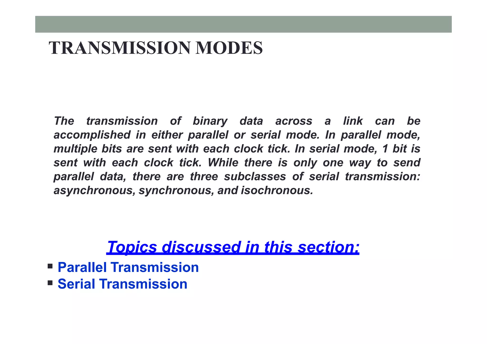
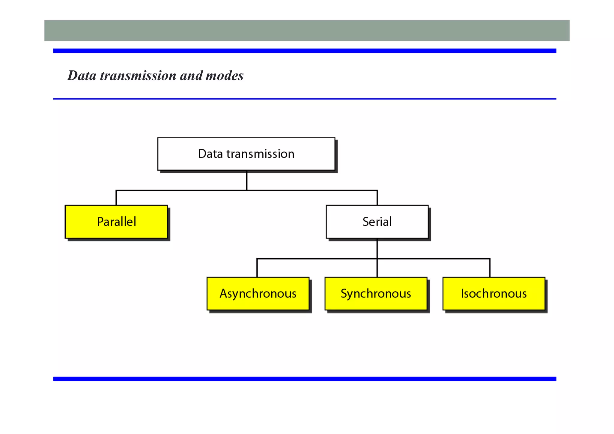
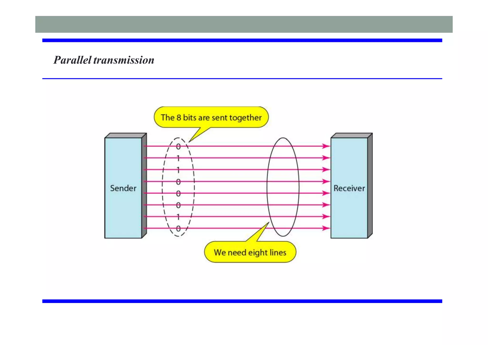
This document discusses different digital transmission techniques for analog signals. It covers the bandwidth requirements of PCM and introduces delta modulation (DM) and its limitations like slope overload and granular noise. Adaptive delta modulation (ADM) is presented as an improvement over DM. Time-division multiplexing (TDM) is also introduced along with the standards DS1/T1/E1. The transmission modes of parallel, asynchronous, synchronous and isochronous serial transmission are defined.


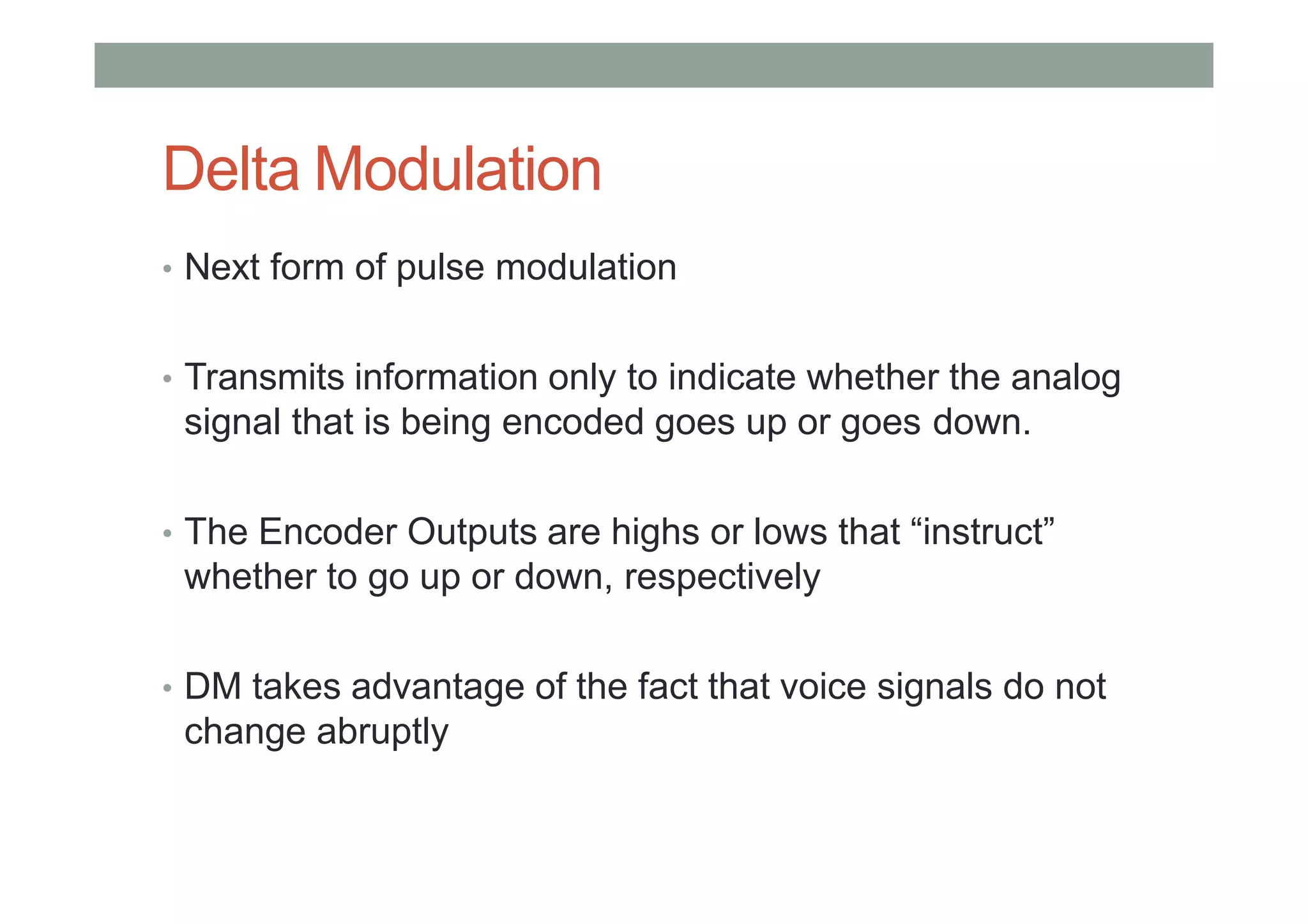
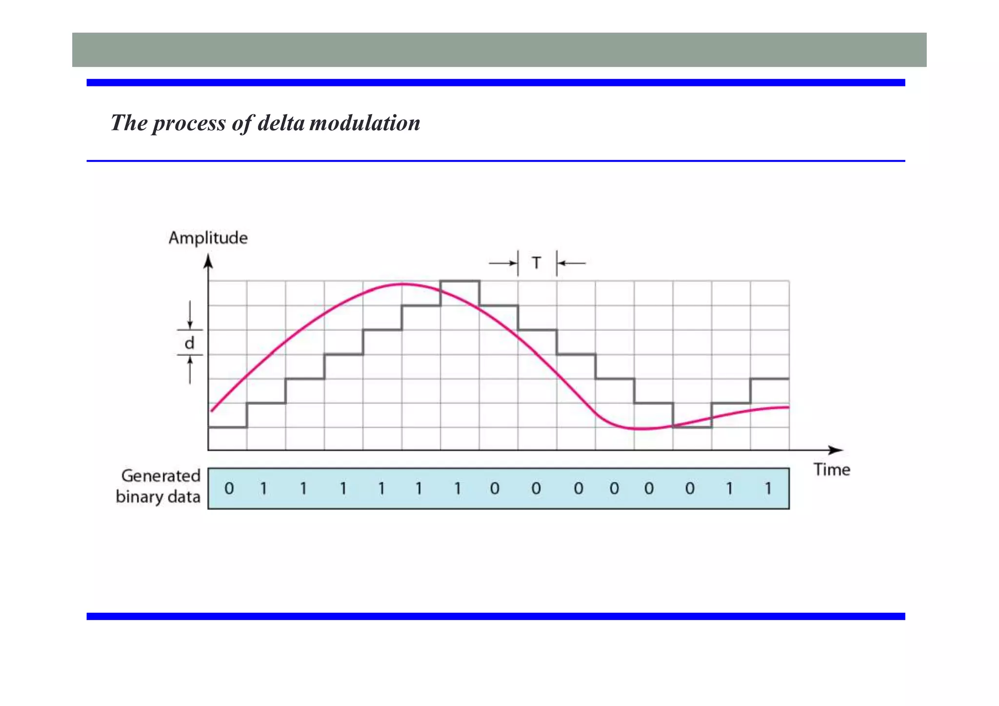
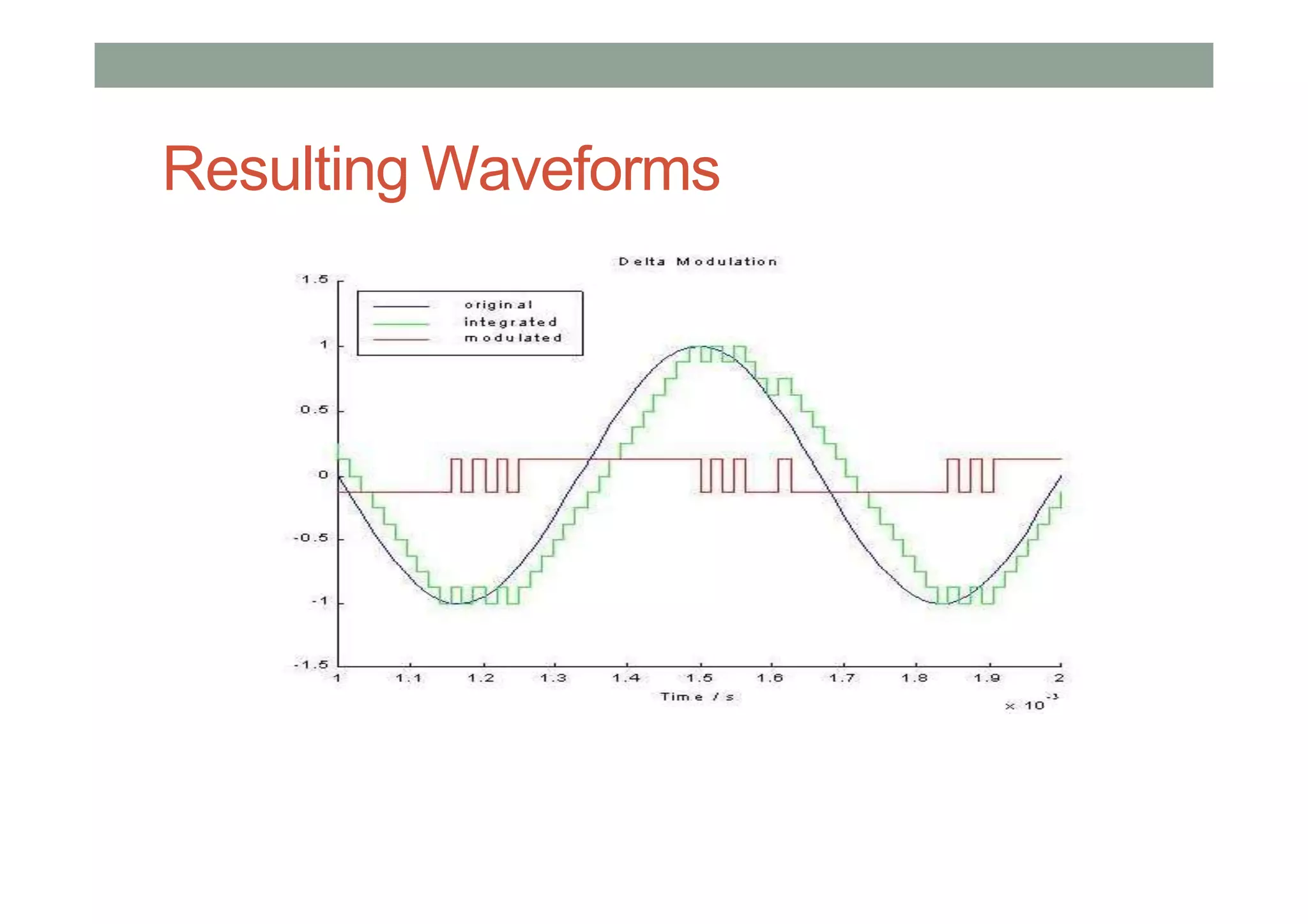
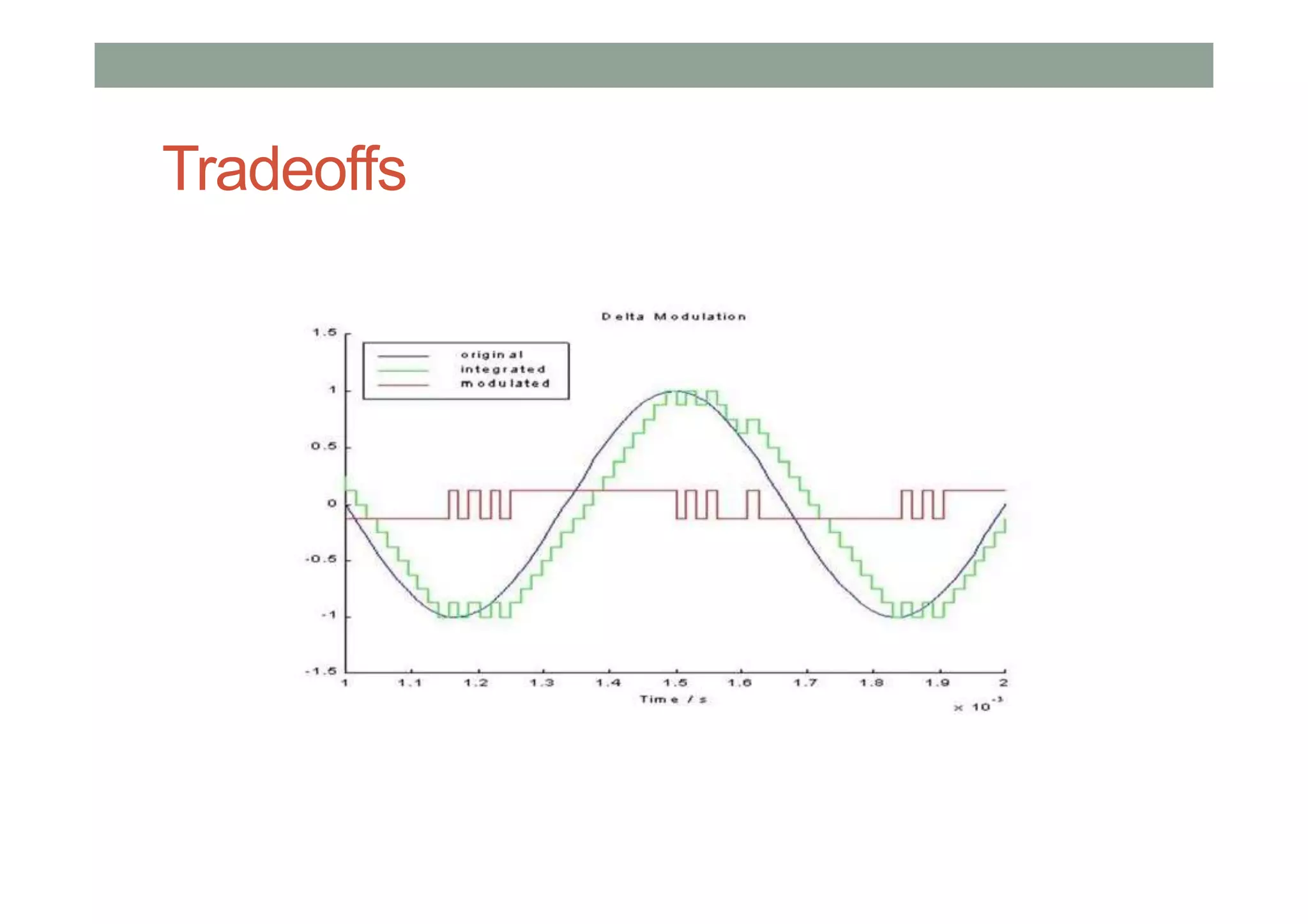
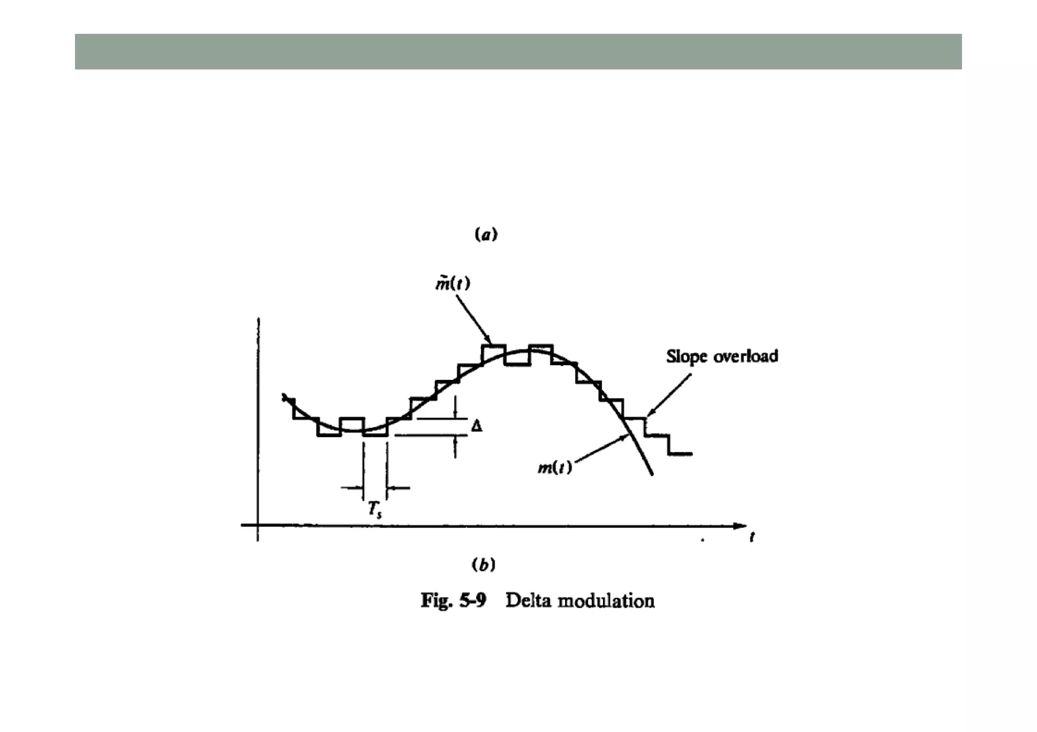
![• Delta modulation, a special case of DPCM where the
differences eQ[n] are represented with 1 bit as ±∆](https://image.slidesharecdn.com/communicationsystem-lec7-200806102232/75/Communication-system-lec7-9-2048.jpg)