Downloaded 16 times

![PEMP
RMD 2501
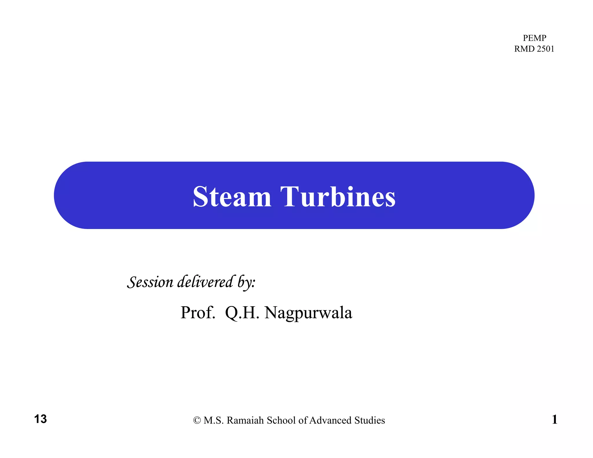
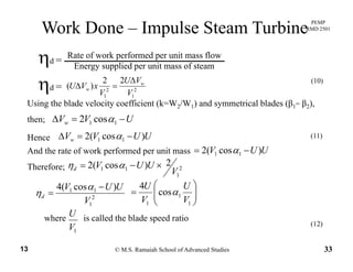
Degree of Reaction
( )
( )
21
hh
hh −
=Λ
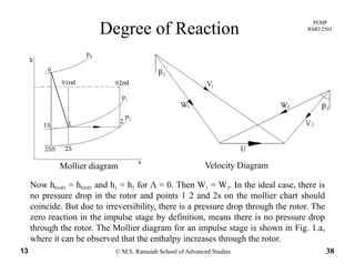
But for a normal stage, V0 = V2 and since h00 = h01 in the nozzle, then;
(17)
( )0201 hh −
We know that (h01 – h02) = ( ) ( ) 0
2
2
2
2
1
21 =
−
+− ww VV
hh
Substituting for (h h ) in equation (17)Substituting for (h1- h2) in equation (17),
( )
( )[ ]
2
1
2
2
2 hh
VV ww −
=Λ
( )
( )[ ]
2
1
2
2
2
ww
VVU
VV
−
−
=
(18)
( )[ ]02012 hh − ( )[ ]212 ww VVU −
Assuming the axial velocity is constant through out the stage, then
( )VV − 22
(18)
( )
( )[ ]UVVUU
VV
ww
ww
−++
−
=Λ
21
12
2
( )( )VVVV +−
© M.S. Ramaiah School of Advanced Studies13 36
( )( )
( )[ ]21
1212
2 ww
wwww
VVU
VVVV
+
+−
=Λ (19)](https://image.slidesharecdn.com/steamturbines-191229120443/85/Steam-turbines-36-320.jpg)
![PEMP
RMD 2501
F t 1
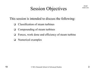
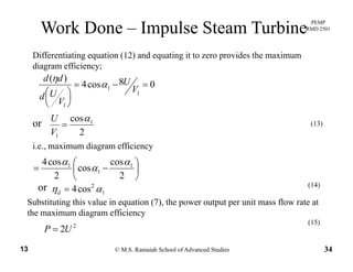
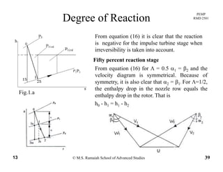
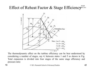
Effect of Reheat Factor & Stage Efficiency
For stage 1
111
1
1
'
21
21
1
1
1.,. ssa
s
a
s
a
s WWor
W
W
hh
hh
W
W
ei Δ=Δ
Δ
=
−
−
== ηη
[ ][ ]44332211 ssssssssaa WWWWWW Δ+Δ+Δ+ΔΣ=ΣΔ=Δ∴ ηηηη
For same stage efficiency in each stage 4321 ssss ηηηη ===
[ ][ ] sssssssa WWWWWW ΣΔ=Δ+Δ+Δ+ΔΣ= ηη 4321 (23)
From equation (22) and (23),
s
s
ss
W
W
WW
ΣΔ
=∴
ΣΔ=
ηη
ηη
0
00
(24)
s
s
W
ηη0
The slope of constant pressure lines on h-s plane is given by
T
h
⎟
⎞
⎜
⎛ ∂
© M.S. Ramaiah School of Advanced Studies13 45
T
s
h
p
=⎟
⎠
⎞
⎜
⎝
⎛
∂
∂](https://image.slidesharecdn.com/steamturbines-191229120443/85/Steam-turbines-45-320.jpg)
![PEMP
RMD 2501
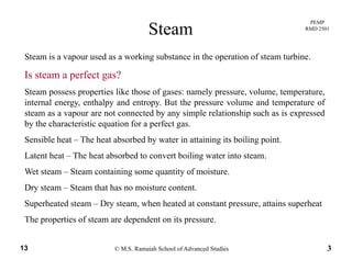
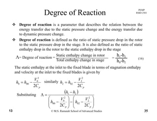
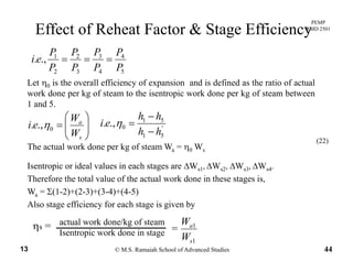
Effect of Reheat Factor & Stage Efficiency
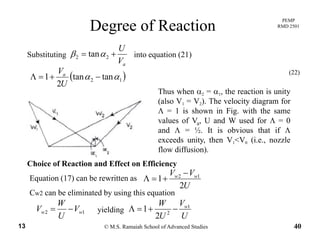
This shows that the constant pressure lines must diverge towards the right.
Therefore
.
F i I i b i h h h l i h
1>
ΣΔ
s
s
W
W
For expansion process. It is obvious that the enthalpy increases when we move
towards right along the constant pressure line. Hence the summation of ΔWs1
ΔWs1 etc., is more than the total isentropic enthalpy drop Ws
Th ti f ti f i t i th l d f i di id l t t th t t l
[ ] [ ])4()3()2()21( ''''
4321 −+−+−+−Σ
=
Δ+Δ+Δ+ΔΣ
=
cbaWWWW
RF ssss
The ratio of summation of isentropic enthalpy drop for individual stage to the total
isentropic enthalpy drop as a whole is called Reheat factor. Thus
)51( −W
RF
s
s
s
W
W
RF
ΣΔ
=
Therefore the overall efficiency of the expansion process
(25)
As
Therefore the overall efficiency of the expansion process,
RFstage ×=ηη0
(26)
1)/( >ΣΔ= ss WWRF
th ll ffi i f th t bi i t th th t ffi i i
© M.S. Ramaiah School of Advanced Studies13 46
the overall efficiency of the turbine η0 is greater than than stage efficiencies ηs
sei ηη >0.,. for turbines (27)](https://image.slidesharecdn.com/steamturbines-191229120443/85/Steam-turbines-46-320.jpg)

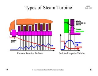
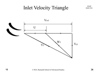
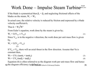
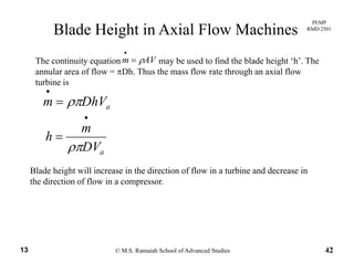
This document discusses steam turbines. It begins by outlining the session objectives which are to classify steam turbines, discuss compounding of steam turbines, and cover forces, work done and efficiency. It then provides information on steam properties, the steam power plant process, types of steam turbines including impulse and reaction turbines, and losses that occur in steam turbines. It also discusses velocity triangles used to understand flow in turbine blades.

![[PPT] on Steam Turbine](https://cdn.slidesharecdn.com/ss_thumbnails/spsharmafinalppt-140608082156-phpapp01-thumbnail.jpg?width=640&height=640&fit=bounds)


