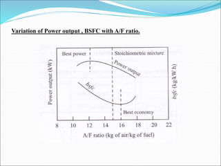
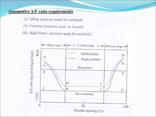
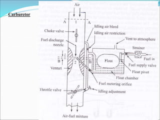
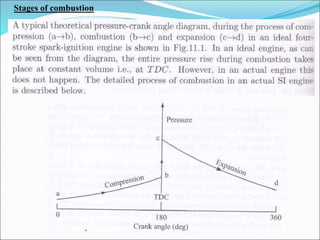
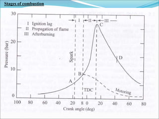
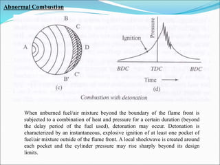
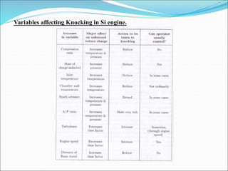
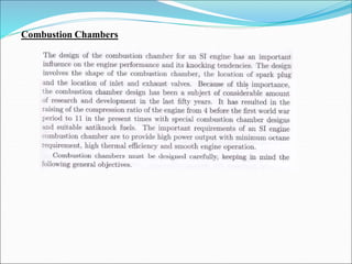
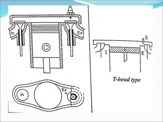
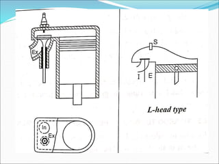
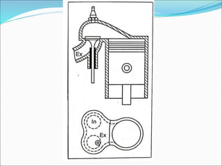
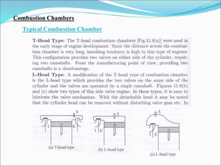
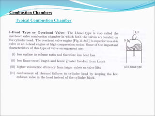
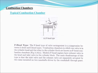
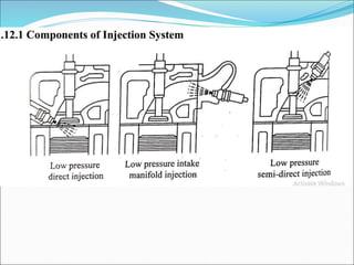
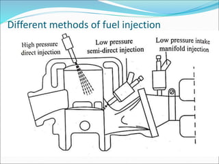
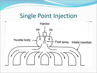
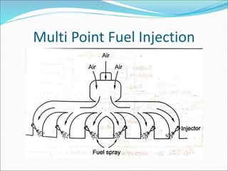
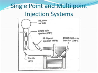
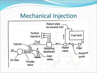
UNIT I SPARK IGNITION ENGINES
Air-fuel ratio requirements – stages of combustion – normal
and abnormal combustion – factors affecting knock – fuel
injection systems – mono point, multipoint and direct injection
combustion chambers – effects of compression ratio –
introduction to thermodynamic analysis of combustion process.
Air-fuel ratio or Mixture requirements
Variation of Power output , BSFC with A/F ratio.
Automotive A/F ratio requirements
Carburetor
Stages of combustion
Normal Combustion
Under ideal conditions the common internal combustion engine burns the
fuel/air mixture in the cylinder in an orderly and controlled fashion.
Abnormal Combustion
When unburned fuel/air mixture beyond the boundary of the flame front is
subjected to a combination of heat and pressure for a certain duration (beyond
the delay period of the fuel used), detonation may occur. Detonation is
characterized by an instantaneous, explosive ignition of at least one pocket of
fuel/air mixture outside of the flame front. A local shockwave is created around
each pocket and the cylinder pressure may rise sharply beyond its design
limits.
Knocking
Knocking (also called knock, detonation, spark knock, pinging or pinking) in spark-
ignition IC engine occurs when combustion of the air/fuel mixture in the cylinder
starts off correctly in response to ignition by the spark plug, but one or more pockets
of air/fuel mixture explode outside the envelope of the normal combustion front.
The fuel-air charge is meant to be ignited by the spark plug only, and at a precise
point in the piston's stroke. Knock occurs when the peak of the combustion process
no longer occurs at the optimum moment for the 4 stroke cycle. The shock wave
creates the characteristic metallic "pinging" sound, and cylinder pressure increases
dramatically. Effects of engine knocking range from inconsequential to completely
destructive.
Factors affecting knock
1. Density Factors
1. Density Factors
2. Time Factors
2. Time Factors
3. Composition Factors
Variables affecting Knocking in Si engine.
Combustion Chambers
Combustion Chamber design
for SI Engine
Combustion Chambers
1. Smooth Engine Operation
Combustion Chambers
2. High Power Output and thermal Efficiency
Combustion Chambers
Typical Combustion Chamber
Combustion Chambers
Typical Combustion Chamber
Combustion Chambers
Typical Combustion Chamber
TYPES OF INJECTION SYSTEMS
 The fuel injection system can be classified as:
 1. Gasoline direct injection into the cylinder (GDI)
 2. Port injection
(a) Timed
(b) Continuous
 3. Manifold injection
 i) Continuous injection systems
This system usually has a rotary pump. The pump
maintains a fuel line gauge pressure of about 0.75 to 1.5
bar. The system injects the fuel through a nozzle located
in the manifold immediately downstream of the throttle
plate
ii) Timed fuel injection system:
This system has a fuel supply pump which sends
fuel at a low pressure of about 2 bar when the engine is
running at maximum speed. A fuel metering or injection
pump and a nozzle are the other parts of the system
Different methods of fuel injection
Single Point Injection
Multi Point Fuel Injection
Single Point and Multi point
Injection Systems
Mechanical Injection
Electronic Injection

UNIT-I SPARK IGNITION ENGINES.ppt