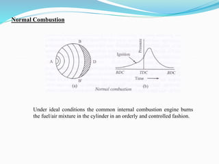
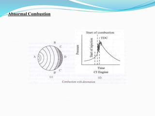
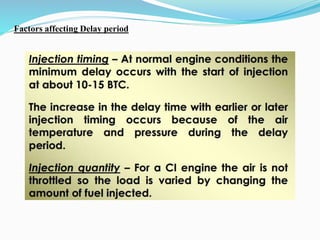
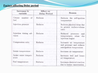
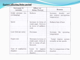
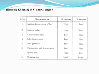
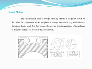
COMPRESSION IGNITION ENGINES
Diesel Fuel Injection Systems - Stages of combustion – Knocking –
Factors affecting knock – Direct and Indirect injection systems –
Combustion chambers – Fuel Spray behaviour – Spray structure and
spray penetration – Air motion - Introduction to Turbocharging.
The main purpose of the fuel injection system is
to deliver fuel into the cylinders of an engine. In
order for the engine to effectively make use of
this fuel:
 Fuel must be injected at the proper time, that is, the
injection timing must be controlled and
 The correct amount of fuel must be delivered to meet
power requirement, that is, injection metering must
be controlled.
Many specialized concepts and terms are used to
describe the components and the operation of
diesel fuel injection systems.
 Nozzle
 Nozzle
 Injector commonly refers to the nozzle holder and
nozzle assembly holder or injector body
 Start of injection (SOI) or injection timing
 Start of delivery
 End of injection (EOI)
 Injected fuel quantity
 Injection duration
 Injection pattern
 Multiple injection event
 Low pressure side components—These components
serve to safely and reliably deliver fuel from the tank to
the fuel injection system. Low pressure side components
include the fuel tank, fuel supply pump and the fuel
filter.
 High pressure side components—Components that
create high pressures, meter and deliver the fuel to
the combustion chamber. They include the high
pressure pump the fuel injector and fuel injection
nozzle. Some systems may also include an accumulator.
Stages of combustion in CI
engine
In the Compression Ignition Engine, the combustion
process will be completed in the four stages in an actual
engine.
Ignition Lag
Rapid Combustion
Controlled Combustion
After Burning
Ignition Lag
 The time interval between the injection of the fuel
and the start of the self-ignition of the fuel is known
as ignition lag or Ignition delay.
 It is also referred to as the preparation phase
 The fuel does not ignite immediately upon the
injection of fuel into the combustion chamber.
 There will be a definitely a certain amount of period
will be delayed between the first droplet of the
fuel injected into the combustion chamber and
the time at which it starts the burning phase.
 There are two chances that can cause the ignition
delay. Physical delay and chemical delay.
 Physical delay due to the complete injection of fuel,
atomisation, vaporization and mixing of air and fuel
and raised to its self-ignition point.
 The chemical delay due to the burning slowly starts
and then accelerates until the complete ignition takes
place.
Rapid Combustion
 The period of rapid combustion also known as the
uncontrolled combustion.
 This rapid combustion will starts right After the
ignition delay period ends.
 During this period the heat release is maximum.
 The pressure released during this period depends
on the ignition delay period.
 If the ignition delay period is more, then the
pressure rise is more due to the more fuel will be
accumulated during the delay period.
Controlled Combustion
 The rapid combustion followed by the third stage
called the controlled combustion.
 During the rapid combustion, the cycle reaches its
maximum pressure and the temperature.
 Which means the fuel droplets injected into the
combustion chamber during the rapid combustion
stage will burn faster with reduced ignition delay as
soon as they find the necessary oxygen and any
further pressure rise is controlled by the injection
 At the point at where it reaches the maximum
cycle pressure the rapid combustion ends and
the controlled combustion starts.
 The period of the controlled combustion is
assumed to end at the maximum cycle
temperature.
After Burning
 The combustion process will not stop right
after the completion of the injection
process.
 The unburnt particles left in the combustion
particles will start burning as soon as they
get in contact with the oxygen.
 This process continued for a certain period
amount of time called the after burning.
 Knocking, in an internal-combustion engine, sharp
sounds caused by premature combustion of part of
the compressed air-fuel mixture in the cylinder.
 In a properly functioning engine, the charge burns with
the flame front progressing smoothly from the point of
ignition across the combustion chamber.
 However, at high compression ratios, depending on the
composition of the fuel, some of the charge may
spontaneously ignite ahead of the flame front and
burn in an uncontrolled manner, producing intense high-
frequency pressure waves.
 These pressure waves force parts of the engine to vibrate,
which produces an audible knock.
Causes of Knocking
1. Low Quality Fuel
2. Carbon Deposits in the Cylinder Wall, and
3. Advanced or Delayed Sparking
4. Improper fuel supply.
Knocking in CI Engine
Knocking in SI and CI Engine
Normal Combustion
Under ideal conditions the common internal combustion engine burns
the fuel/air mixture in the cylinder in an orderly and controlled fashion.
Abnormal Combustion
Factors affecting Delay period
Reducing Knocking in SI and CI engine
The main reason of knocking in a CI engine is the ignition delay,
after the compression stroke has ended.
Following parameters will minimize knocking in CI
engines.
 Compression ratio: high
 Self ignition temp: low
 Delay period: less
 Inlet temp and pressure: high
 Combustion chamber temp: high
 RPM : low
 Engine size : small
 Cetane Rating: High
Combustion Chamber in CI engine
1. Direct Injection type
2. Indirect Injection type
1. Direct Injection Type.
• Shallow depth Chamber
• Hemispherical Chamber
• Cylindrical Chamber
• Toroidal Chamber
Direct Injection Type
Shallow depth Chamber Hemispherical Chamber
Direct Injection Type
Cylindrical Chamber Toroidal Chamber
2. Indirect Injection Type.
Indirect Injection Type
1. Swirl Chamber
Indirect Injection Type
2. Precombustion Chamber
Indirect Injection Type
3. Air-Cell Combustion Chamber
 A significant difference between a
turbocharged diesel engine and a traditional
naturally aspirated gasoline engine is the air
entering a diesel engine is compressed
before the fuel is injected. This is where the
turbocharger is critical to the power output
and efficiency of the diesel engine.
 It is the job of the turbocharger to compress more
air flowing into the engine’s cylinder. When air is
compressed the oxygen molecules are packed
closer together. This increase in air means that
more fuel can be added for the same size naturally
aspirated engine. This then generates increased
mechanical power and overall efficiency
improvement of the combustion process.
Therefore, the engine size can be reduced for a
turbocharged engine leading to better packaging,
weight saving benefits and overall improved fuel
economy.
Turbo charging
1. Exhaust Turbo charging of Single cylinder engine.
Turbo charging
2. Exhaust Turbo charging of a V type engine.
Fuel Spray Behaviour
Spray Formation
 The spray characteristics of fuel mainly
depend on the fuel injection pressure,
density, viscosity, ambient pressure, and
temperature.
 Among these parameters, fuel injection
pressure significantly affects the spray
structure
Fuel Spray
AIR MOTION WITHIN THE CYLINDER
The air motion inside the cylinder greatly influences the performance of diesel
engines. It is one of the major factors that controls the fuel-air mixing in diesel engines. Air-
fuel mixing influences combustion, performance and emission level in the engine. The air
motion inside the cylinder mainly depends on manifold design, inlet and exhaust valve profile
and combustion chamber configuration. The initial in-cylinder intake flow pattern is set up by
the intake process, and then it is modified during the compression process. The shape of the
bowl in the piston and the intake system, control the turbulence level and air-fuel mixing of the
DI diesel engine. The variation of shape of intake system, shape of piston cavity, etc. lead to a
change in the flow field inside the engine.
EFFECTS OF AIR MOTION
• Atomizes the injected fuel into droplets of different sizes.
• Distributes the fuel droplets uniformly in the air charge.
• Mixes injected fuel droplets with the air mass.
• Assists combustion of fuel droplets.
• Peels off the combustion products from the surface of the burning drops as they are being
consumed.
• Supplies fresh air to the interior portion of the fuel drops and thereby ensures complete
combustion.
• Reduces delay period.
• Reduces after burning of the fuel.
• Better utilization of air contained in the cylinder.
TYPES OF AIR MOTION
The air motion in a diesel engine is generally caused by either by the intake port
during the suction stroke or by combustion chamber geometry during the
compression stroke. Three different elements of the air motion present during
intake to expansion strokes in a diesel engine cylinder have been classified as
1) Swirl
2) Squish
3) Turbulence
Swirl Motion
Swirl is defined as the organized rotation of the charge about the cylinder
axis. It is created by bringing the intake flow into the cylinder with an initial angular
momentum. Swirl is generated during the intake process in DI diesel engines by the
intake port and subsequently by combustion chamber geometry during the compression
stroke.
Squish Motion
The squish motion of air is brought about by a recess in the piston crown. At
the end of the compression stroke, the piston is brought to within a very small distance
from the cylinder head. This fact causes a flow of air from the periphery of the cylinder
to its center and into the recess in the piston crown.

unit-2-COMPRESSION IGNITION engine system

  • 1.
    COMPRESSION IGNITION ENGINES DieselFuel Injection Systems - Stages of combustion – Knocking – Factors affecting knock – Direct and Indirect injection systems – Combustion chambers – Fuel Spray behaviour – Spray structure and spray penetration – Air motion - Introduction to Turbocharging.
  • 2.
    The main purposeof the fuel injection system is to deliver fuel into the cylinders of an engine. In order for the engine to effectively make use of this fuel:  Fuel must be injected at the proper time, that is, the injection timing must be controlled and  The correct amount of fuel must be delivered to meet power requirement, that is, injection metering must be controlled.
  • 3.
    Many specialized conceptsand terms are used to describe the components and the operation of diesel fuel injection systems.  Nozzle  Nozzle  Injector commonly refers to the nozzle holder and nozzle assembly holder or injector body  Start of injection (SOI) or injection timing  Start of delivery  End of injection (EOI)  Injected fuel quantity  Injection duration
  • 4.
     Injection pattern Multiple injection event  Low pressure side components—These components serve to safely and reliably deliver fuel from the tank to the fuel injection system. Low pressure side components include the fuel tank, fuel supply pump and the fuel filter.  High pressure side components—Components that create high pressures, meter and deliver the fuel to the combustion chamber. They include the high pressure pump the fuel injector and fuel injection nozzle. Some systems may also include an accumulator.
  • 5.
    Stages of combustionin CI engine In the Compression Ignition Engine, the combustion process will be completed in the four stages in an actual engine. Ignition Lag Rapid Combustion Controlled Combustion After Burning
  • 7.
    Ignition Lag  Thetime interval between the injection of the fuel and the start of the self-ignition of the fuel is known as ignition lag or Ignition delay.  It is also referred to as the preparation phase  The fuel does not ignite immediately upon the injection of fuel into the combustion chamber.  There will be a definitely a certain amount of period will be delayed between the first droplet of the fuel injected into the combustion chamber and the time at which it starts the burning phase.
  • 8.
     There aretwo chances that can cause the ignition delay. Physical delay and chemical delay.  Physical delay due to the complete injection of fuel, atomisation, vaporization and mixing of air and fuel and raised to its self-ignition point.  The chemical delay due to the burning slowly starts and then accelerates until the complete ignition takes place.
  • 9.
    Rapid Combustion  Theperiod of rapid combustion also known as the uncontrolled combustion.  This rapid combustion will starts right After the ignition delay period ends.  During this period the heat release is maximum.  The pressure released during this period depends on the ignition delay period.  If the ignition delay period is more, then the pressure rise is more due to the more fuel will be accumulated during the delay period.
  • 10.
    Controlled Combustion  Therapid combustion followed by the third stage called the controlled combustion.  During the rapid combustion, the cycle reaches its maximum pressure and the temperature.  Which means the fuel droplets injected into the combustion chamber during the rapid combustion stage will burn faster with reduced ignition delay as soon as they find the necessary oxygen and any further pressure rise is controlled by the injection
  • 11.
     At thepoint at where it reaches the maximum cycle pressure the rapid combustion ends and the controlled combustion starts.  The period of the controlled combustion is assumed to end at the maximum cycle temperature.
  • 12.
    After Burning  Thecombustion process will not stop right after the completion of the injection process.  The unburnt particles left in the combustion particles will start burning as soon as they get in contact with the oxygen.  This process continued for a certain period amount of time called the after burning.
  • 13.
     Knocking, inan internal-combustion engine, sharp sounds caused by premature combustion of part of the compressed air-fuel mixture in the cylinder.  In a properly functioning engine, the charge burns with the flame front progressing smoothly from the point of ignition across the combustion chamber.  However, at high compression ratios, depending on the composition of the fuel, some of the charge may spontaneously ignite ahead of the flame front and burn in an uncontrolled manner, producing intense high- frequency pressure waves.  These pressure waves force parts of the engine to vibrate, which produces an audible knock.
  • 14.
    Causes of Knocking 1.Low Quality Fuel 2. Carbon Deposits in the Cylinder Wall, and 3. Advanced or Delayed Sparking 4. Improper fuel supply.
  • 15.
  • 16.
    Knocking in SIand CI Engine
  • 17.
    Normal Combustion Under idealconditions the common internal combustion engine burns the fuel/air mixture in the cylinder in an orderly and controlled fashion.
  • 18.
  • 19.
  • 20.
  • 21.
  • 22.
  • 23.
  • 24.
    Reducing Knocking inSI and CI engine
  • 25.
    The main reasonof knocking in a CI engine is the ignition delay, after the compression stroke has ended. Following parameters will minimize knocking in CI engines.  Compression ratio: high  Self ignition temp: low  Delay period: less  Inlet temp and pressure: high  Combustion chamber temp: high  RPM : low  Engine size : small  Cetane Rating: High
  • 26.
    Combustion Chamber inCI engine 1. Direct Injection type 2. Indirect Injection type 1. Direct Injection Type. • Shallow depth Chamber • Hemispherical Chamber • Cylindrical Chamber • Toroidal Chamber
  • 27.
    Direct Injection Type Shallowdepth Chamber Hemispherical Chamber
  • 28.
    Direct Injection Type CylindricalChamber Toroidal Chamber
  • 29.
  • 30.
  • 31.
    Indirect Injection Type 2.Precombustion Chamber
  • 32.
    Indirect Injection Type 3.Air-Cell Combustion Chamber
  • 33.
     A significantdifference between a turbocharged diesel engine and a traditional naturally aspirated gasoline engine is the air entering a diesel engine is compressed before the fuel is injected. This is where the turbocharger is critical to the power output and efficiency of the diesel engine.
  • 34.
     It isthe job of the turbocharger to compress more air flowing into the engine’s cylinder. When air is compressed the oxygen molecules are packed closer together. This increase in air means that more fuel can be added for the same size naturally aspirated engine. This then generates increased mechanical power and overall efficiency improvement of the combustion process. Therefore, the engine size can be reduced for a turbocharged engine leading to better packaging, weight saving benefits and overall improved fuel economy.
  • 35.
    Turbo charging 1. ExhaustTurbo charging of Single cylinder engine.
  • 36.
    Turbo charging 2. ExhaustTurbo charging of a V type engine.
  • 38.
  • 40.
  • 41.
     The spraycharacteristics of fuel mainly depend on the fuel injection pressure, density, viscosity, ambient pressure, and temperature.  Among these parameters, fuel injection pressure significantly affects the spray structure
  • 44.
  • 49.
    AIR MOTION WITHINTHE CYLINDER The air motion inside the cylinder greatly influences the performance of diesel engines. It is one of the major factors that controls the fuel-air mixing in diesel engines. Air- fuel mixing influences combustion, performance and emission level in the engine. The air motion inside the cylinder mainly depends on manifold design, inlet and exhaust valve profile and combustion chamber configuration. The initial in-cylinder intake flow pattern is set up by the intake process, and then it is modified during the compression process. The shape of the bowl in the piston and the intake system, control the turbulence level and air-fuel mixing of the DI diesel engine. The variation of shape of intake system, shape of piston cavity, etc. lead to a change in the flow field inside the engine.
  • 50.
    EFFECTS OF AIRMOTION • Atomizes the injected fuel into droplets of different sizes. • Distributes the fuel droplets uniformly in the air charge. • Mixes injected fuel droplets with the air mass. • Assists combustion of fuel droplets. • Peels off the combustion products from the surface of the burning drops as they are being consumed. • Supplies fresh air to the interior portion of the fuel drops and thereby ensures complete combustion. • Reduces delay period. • Reduces after burning of the fuel. • Better utilization of air contained in the cylinder.
  • 51.
    TYPES OF AIRMOTION The air motion in a diesel engine is generally caused by either by the intake port during the suction stroke or by combustion chamber geometry during the compression stroke. Three different elements of the air motion present during intake to expansion strokes in a diesel engine cylinder have been classified as 1) Swirl 2) Squish 3) Turbulence
  • 52.
    Swirl Motion Swirl isdefined as the organized rotation of the charge about the cylinder axis. It is created by bringing the intake flow into the cylinder with an initial angular momentum. Swirl is generated during the intake process in DI diesel engines by the intake port and subsequently by combustion chamber geometry during the compression stroke.
  • 53.
    Squish Motion The squishmotion of air is brought about by a recess in the piston crown. At the end of the compression stroke, the piston is brought to within a very small distance from the cylinder head. This fact causes a flow of air from the periphery of the cylinder to its center and into the recess in the piston crown.