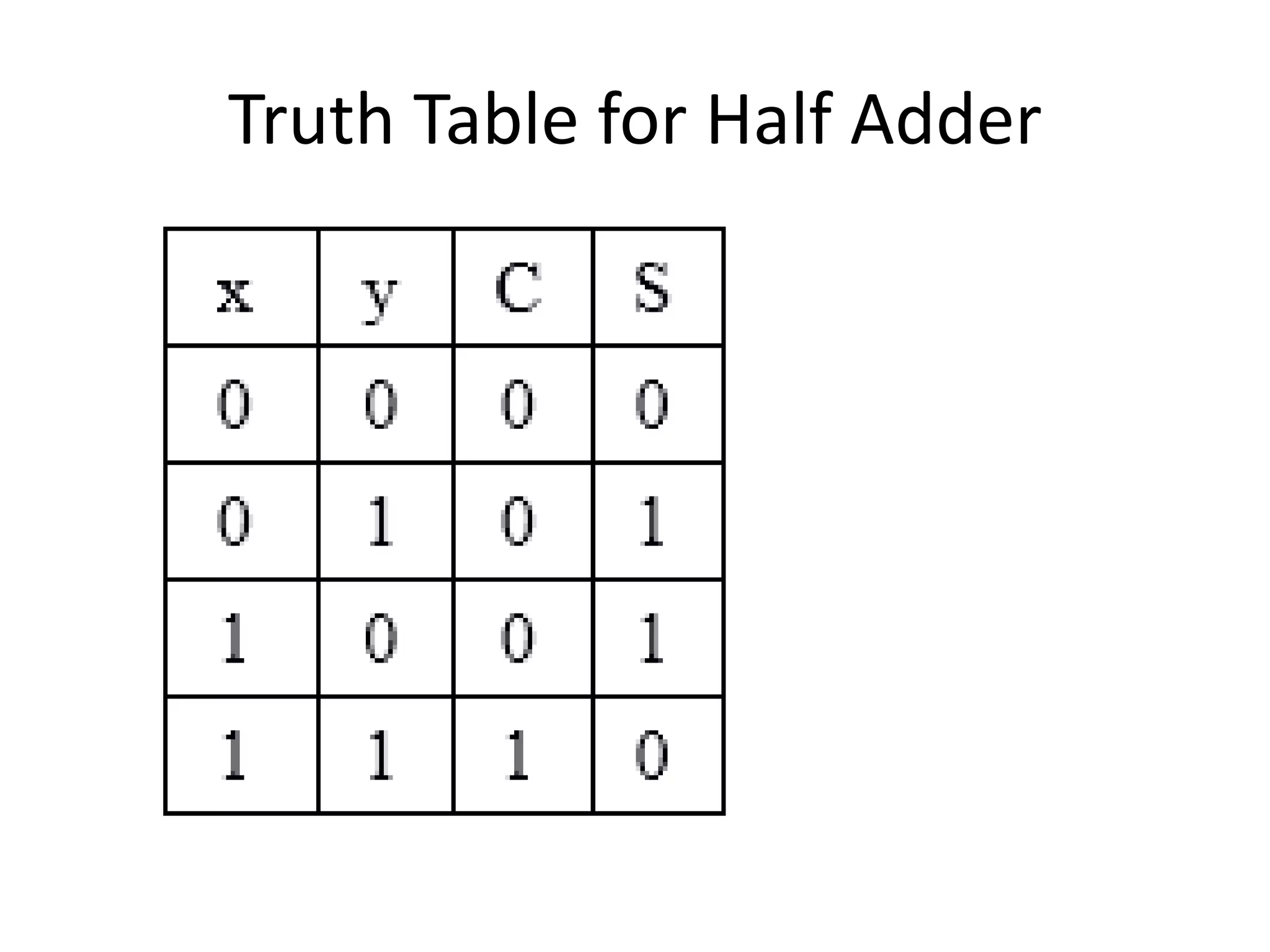
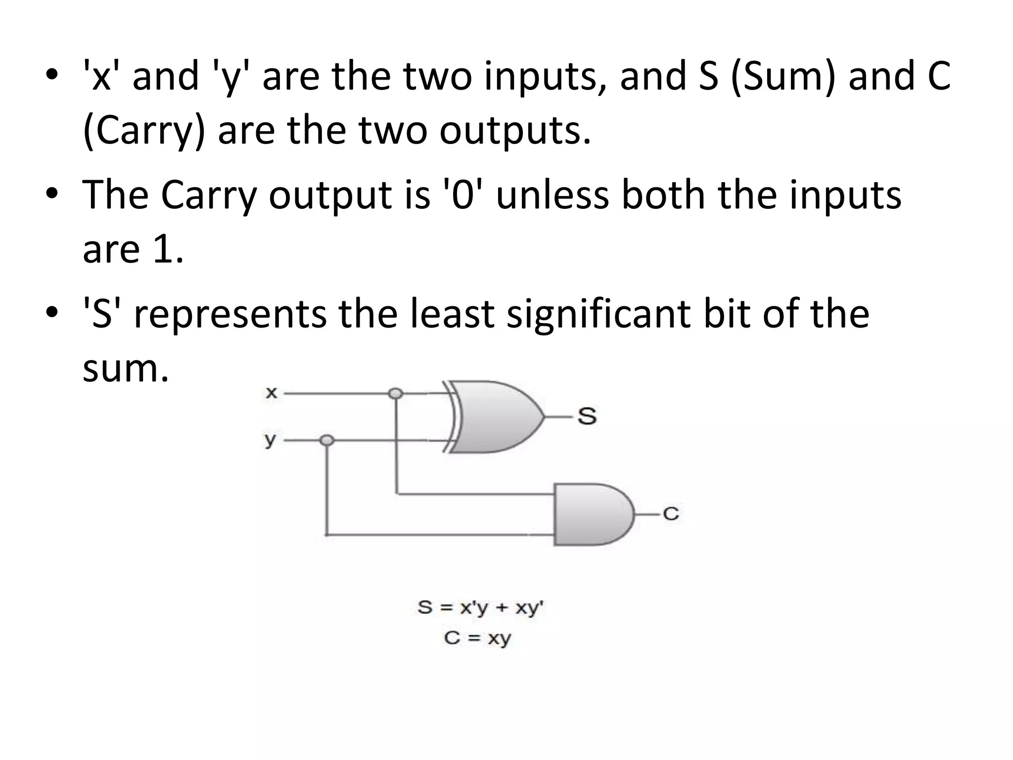
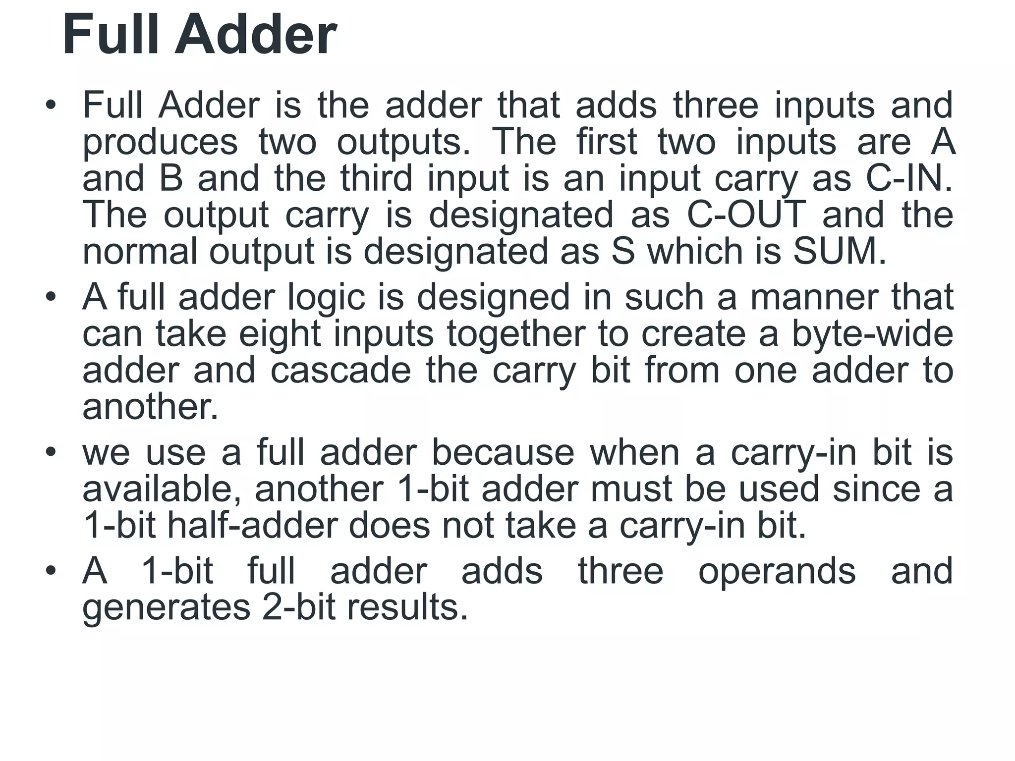
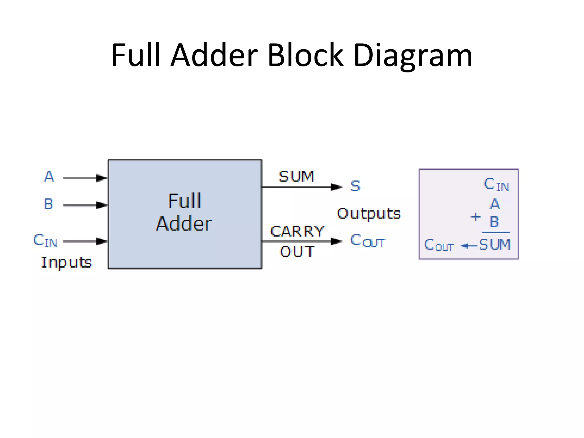
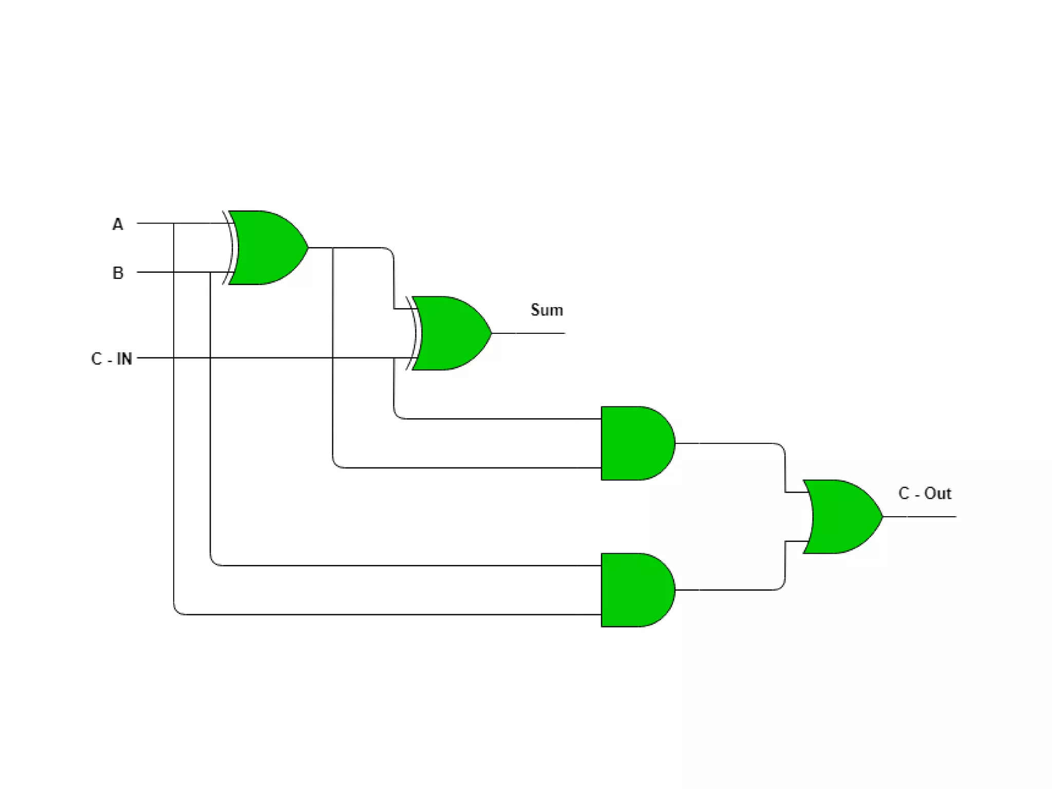
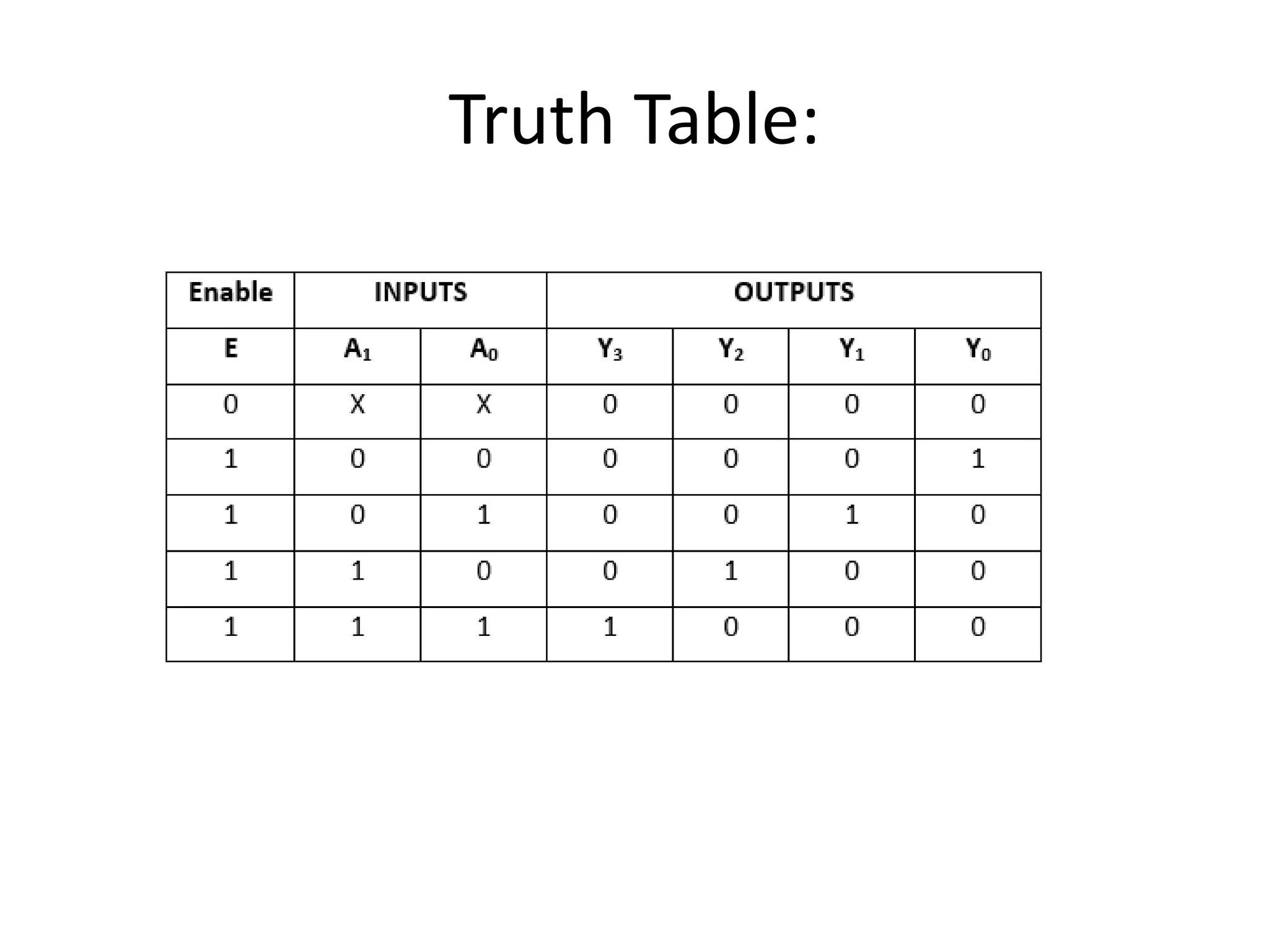
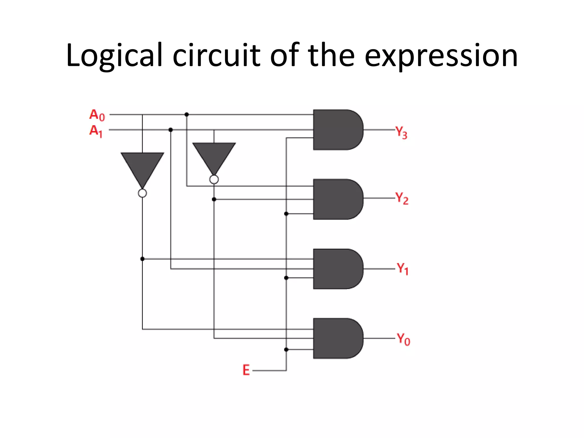
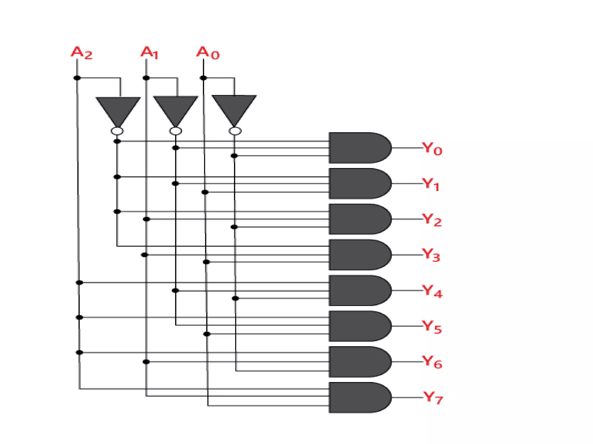
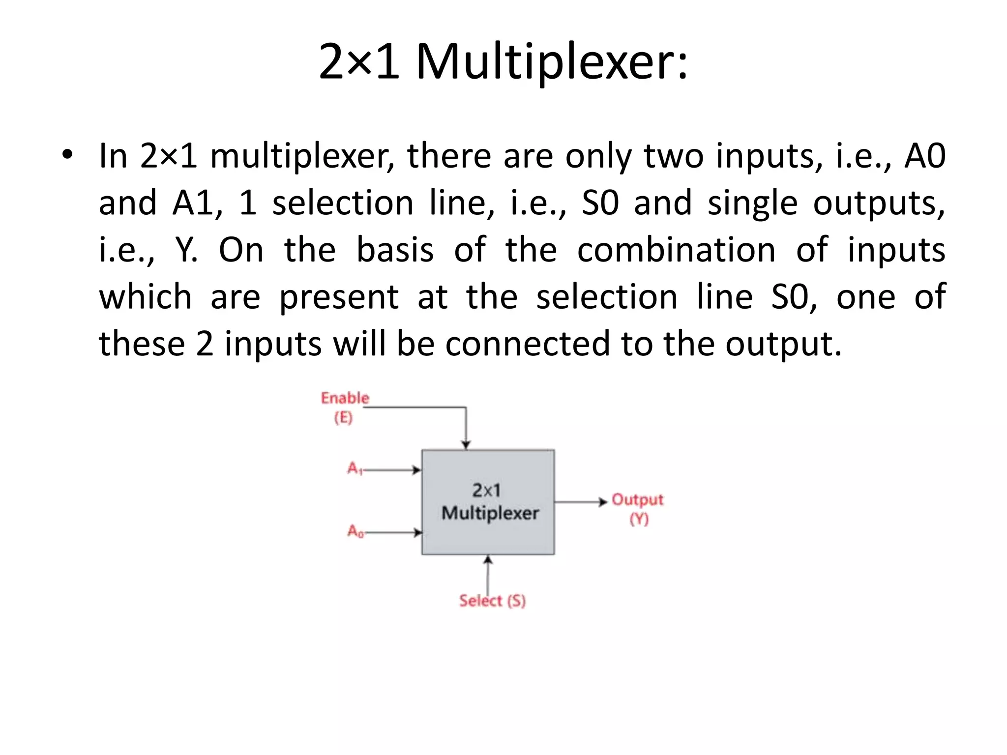
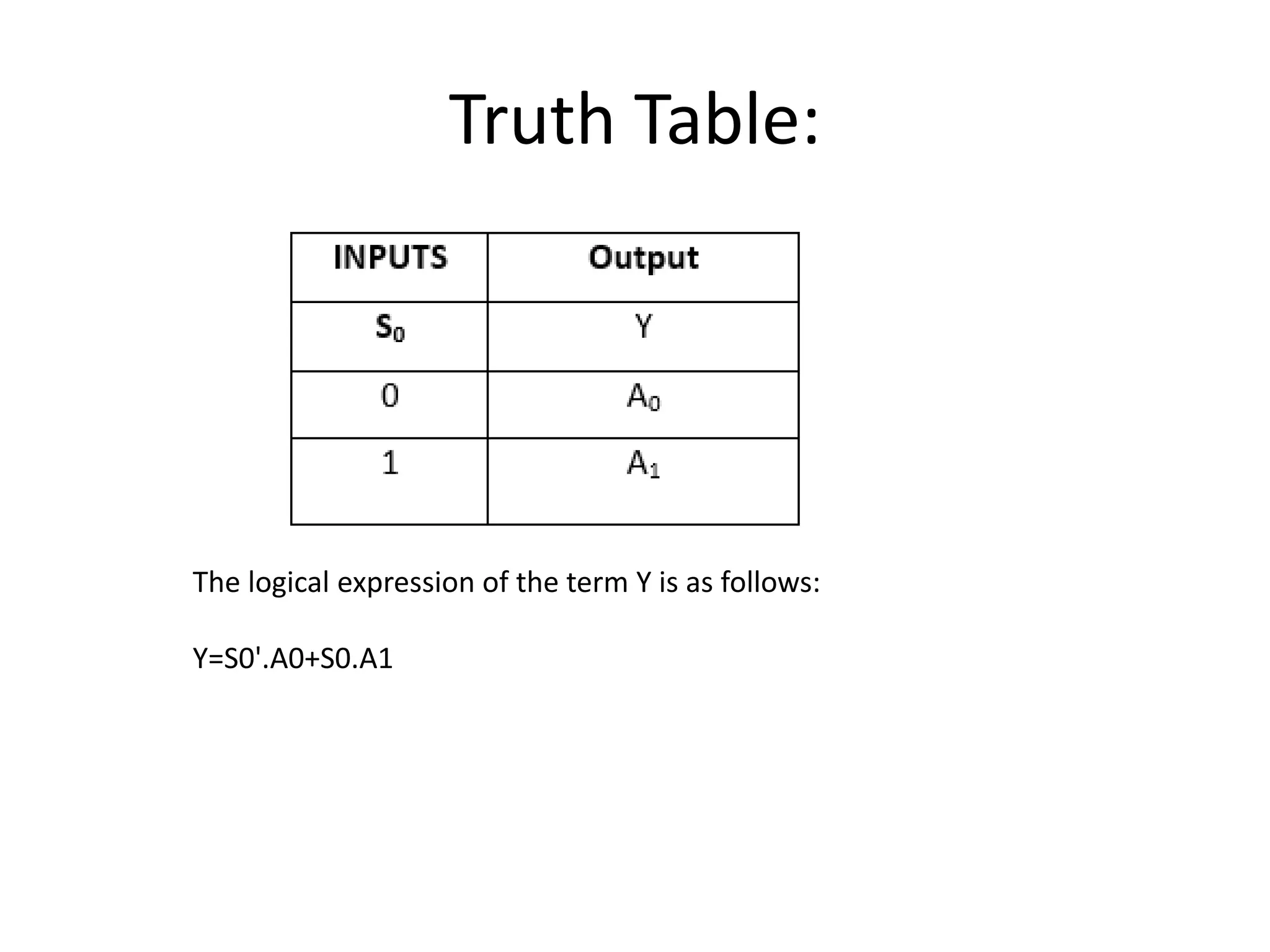
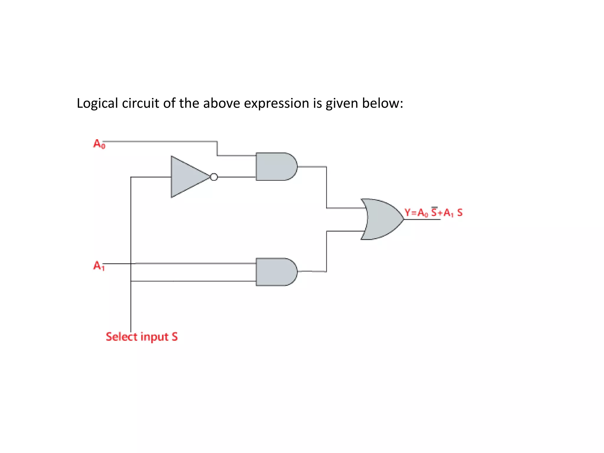
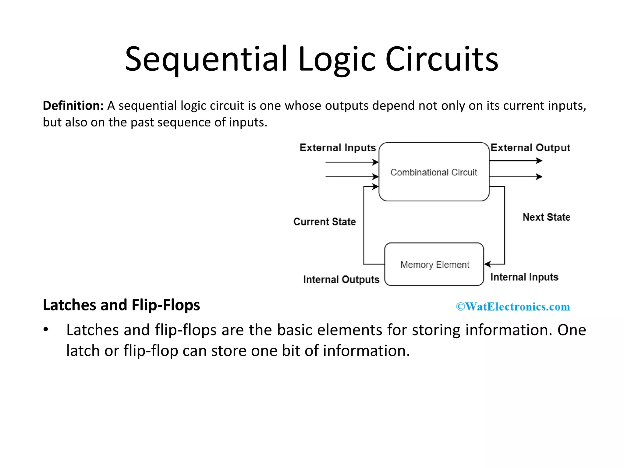
2. Combinational circuit is a circuit in which we
combine the different gates in the circuit, for
example encoder, decoder, multiplexer and
demultiplexer. Some of the characteristics of
combinational circuits are following −
• The output of combinational circuit at any
instant of time, depends only on the levels
present at input terminals.
• The combinational circuit do not use any
memory. The previous state of input does not
have any effect on the present state of the
circuit.
• A combinational circuit can have an n
number of inputs and m number of outputs.
3. • Combinational circuits consist of Logic
gates. These circuits operate with binary
values. The outputs of combinational circuit
depends on the combination of present
inputs. The following figure shows the block
diagram of combinational circuit.
• This combinational circuit has ‘n’ input
variables and ‘m’ outputs. Each combination
of input variables will affect the outputs .
4. Design procedure of Combinational
circuits
• Find the required number of input variables and
outputs from given specifications.
• Formulate the Truth table. If there are ‘n’ input
variables, then there will be 2n possible
combinations. For each combination of input, find
the output values.
• Find the Boolean expressions for each output. If
necessary, simplify those expressions.
• Implement the above Boolean expressions
corresponding to each output by using Logic
gates.
5. Half - Adder
• A Half-adder circuit needs two binary inputs and
two binary outputs. The input variable shows
the augend and addend bits whereas the output
variable produces the sum and carry. We can
understand the function of a half-adder by
formulating a truth table. The truth table for a
half-adder is:
7. • 'x' and 'y' are the two inputs, and S (Sum) and C
(Carry) are the two outputs.
• The Carry output is '0' unless both the inputs
are 1.
• 'S' represents the least significant bit of the
sum.
8. Full Adder
• Full Adder is the adder that adds three inputs and
produces two outputs. The first two inputs are A
and B and the third input is an input carry as C-IN.
The output carry is designated as C-OUT and the
normal output is designated as S which is SUM.
• A full adder logic is designed in such a manner that
can take eight inputs together to create a byte-wide
adder and cascade the carry bit from one adder to
another.
• we use a full adder because when a carry-in bit is
available, another 1-bit adder must be used since a
1-bit half-adder does not take a carry-in bit.
• A 1-bit full adder adds three operands and
generates 2-bit results.
12. Decoder
• The combinational circuit that change the binary
information into 2N output lines is known
as Decoders. The binary information is passed in
the form of N input lines.
• The output lines define the 2N-bit code for the
binary information. In simple words,
the Decoder performs the reverse operation of
the Encoder.
• At a time, only one input line is activated for
simplicity. The produced 2N-bit output code is
equivalent to the binary information.
13. Decoder is a combinational circuit that has ‘n’ input
lines and maximum of 2n output lines. One of these
outputs will be active High based on the combination of
inputs present, when the decoder is enabled. That
means decoder detects a particular code. The outputs
of the decoder are nothing but the min terms of ‘n’
input variables lines, when it is enabled.
14. 2 to 4 line decoder:
• In the 2 to 4 line decoder, there is a total of three inputs, i.e.,
A0, and A1 and E and four outputs, i.e., Y0, Y1, Y2, and Y3. For
each combination of inputs, when the enable 'E' is set to 1,
one of these four outputs will be 1. The block diagram and the
truth table of the 2 to 4 line decoder are given below.
18. Multiplexer
• A multiplexer is a combinational circuit that has 2n input
lines and a single output line. Simply, the multiplexer is a
multi-input and single-output combinational circuit. The
binary information is received from the input lines and
directed to the output line. On the basis of the values of
the selection lines, one of these data inputs will be
connected to the output.
• Unlike encoder and decoder, there are n selection lines and
2n input lines. So, there is a total of 2N possible
combinations of inputs. A multiplexer is also treated as
Mux.
19. 2×1 Multiplexer:
• In 2×1 multiplexer, there are only two inputs, i.e., A0
and A1, 1 selection line, i.e., S0 and single outputs,
i.e., Y. On the basis of the combination of inputs
which are present at the selection line S0, one of
these 2 inputs will be connected to the output.
22. Sequential Logic Circuits
Definition: A sequential logic circuit is one whose outputs depend not only on its current inputs,
but also on the past sequence of inputs.
Latches and Flip-Flops
• Latches and flip-flops are the basic elements for storing information. One
latch or flip-flop can store one bit of information.
23. • for latches, their outputs are constantly
affected by their inputs as long as the enable
signal is asserted. In other words, when they
are enabled, their content changes
immediately when their inputs change.
• Flip-flops, on the other hand, have their
content change only either at the rising or
falling edge of the enable signal. This enable
signal is usually the controlling clock signal.
After the rising or falling edge of the clock, the
flip-flop content remains constant even if the
input changes.