Download to read offline

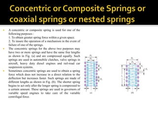
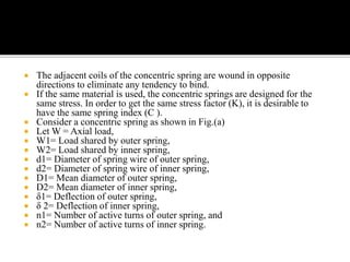
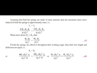

Concentric or composite springs are used to obtain greater spring force in less space or ensure mechanism function if one spring fails. They have two or more same-length springs compressed equally. Concentric springs can also provide nonlinear spring force by using springs of different lengths, so the shorter spring engages after longer spring compresses. The coils wind in opposite directions to prevent binding. When using the same material, concentric springs are designed for equal stress by having the same spring index. A problem is presented involving calculating load sharing, dimensions, and coils of a concentric aircraft engine valve spring under given deflection, stress, spring index, and material properties.