Downloaded 139 times


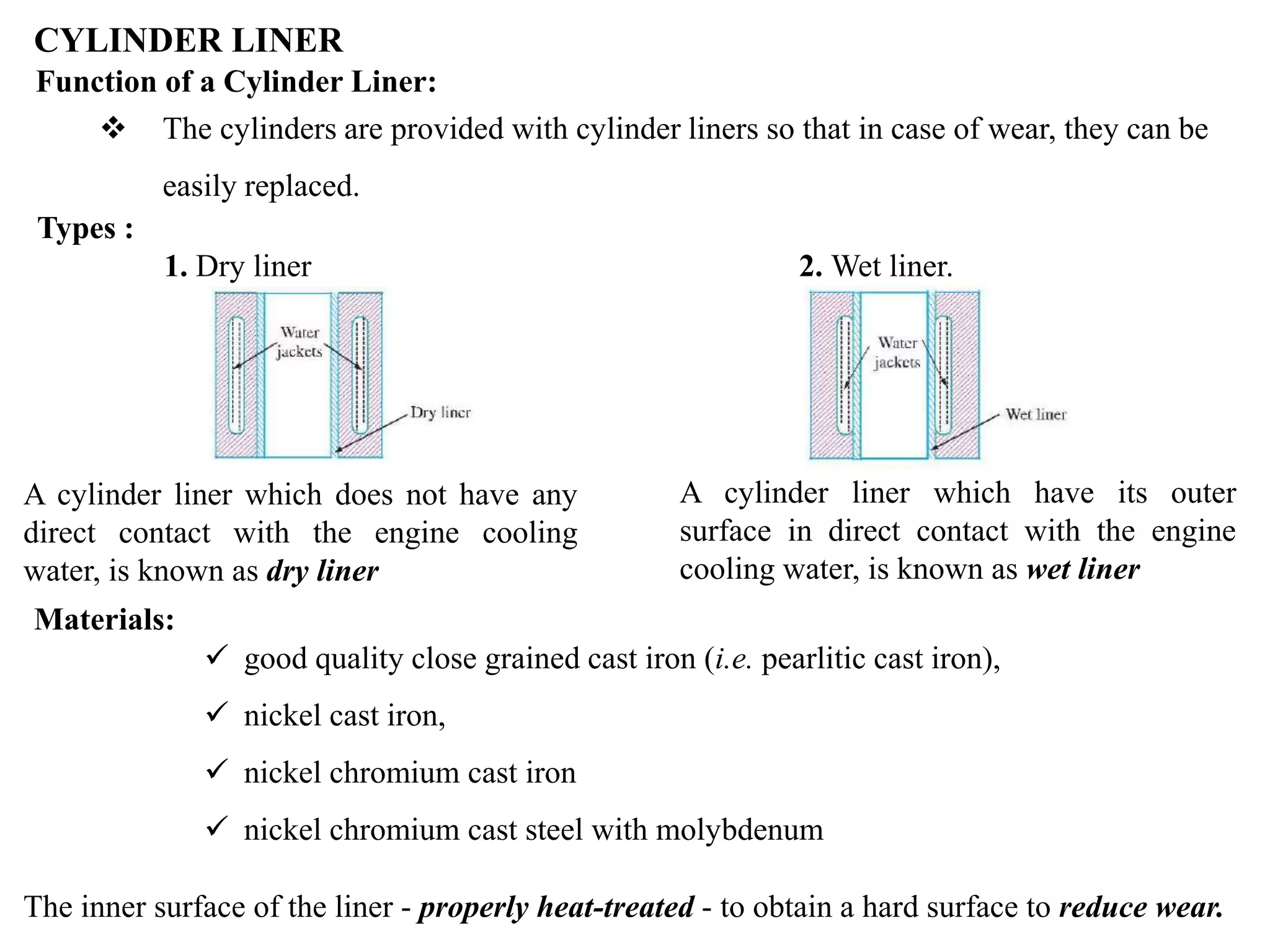


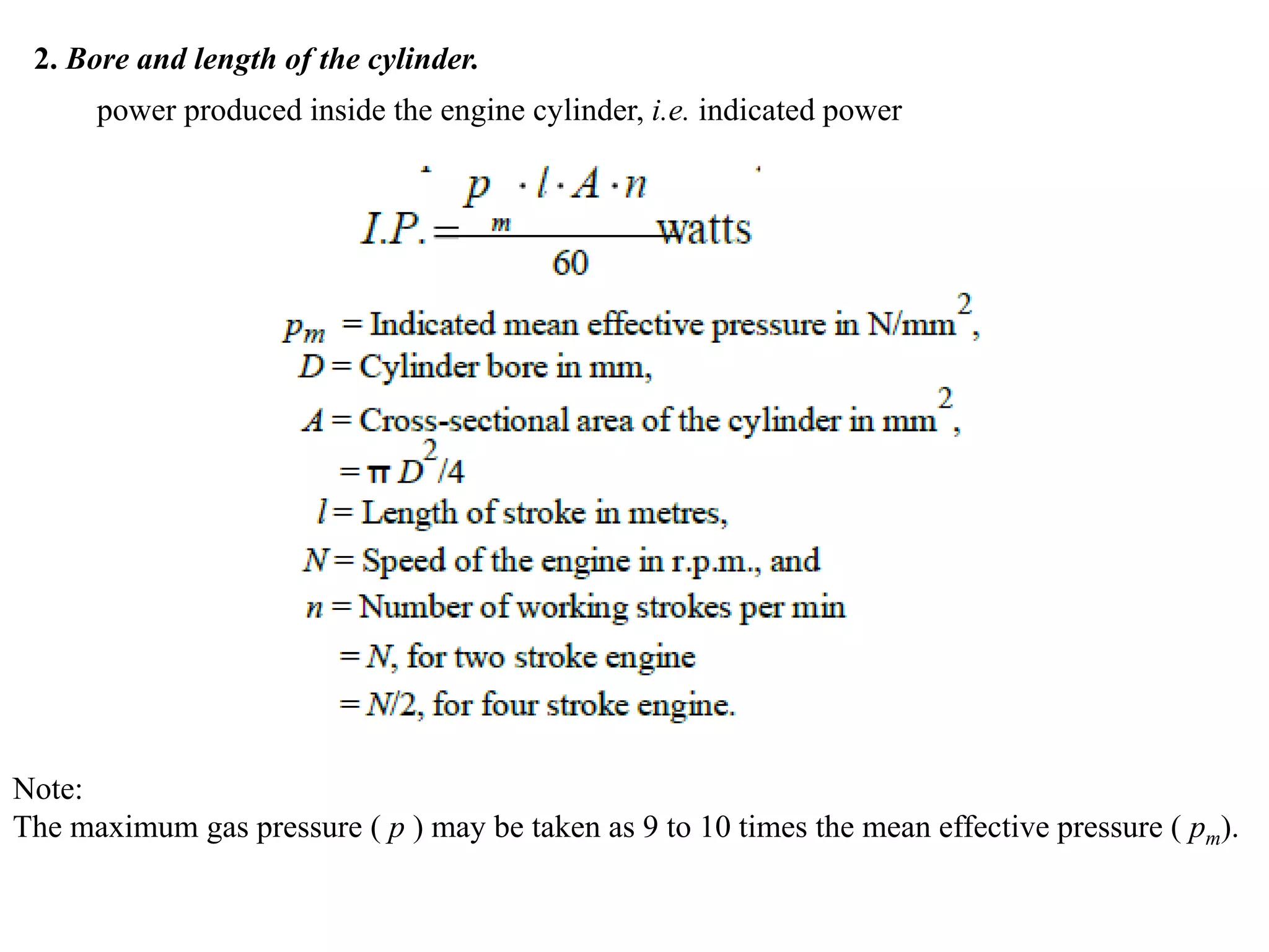


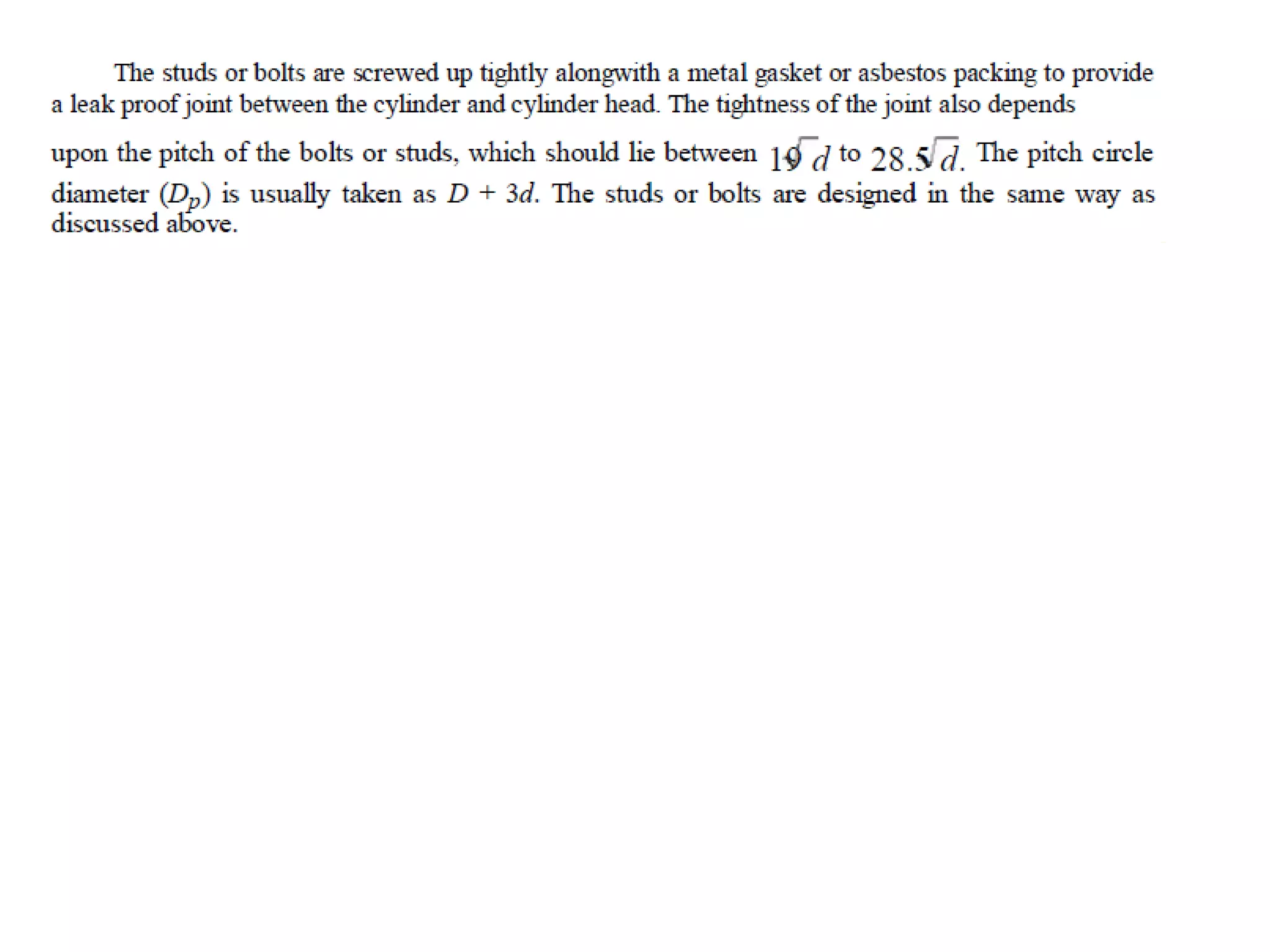


The document discusses the design of cylinder components in an internal combustion engine. It describes the principal parts of an engine including the cylinder and cylinder liner. The cylinder is usually made of cast iron or cast steel to withstand high temperatures and pressures. Cylinder liners are used for replaceability and can be dry or wet types. The design of a cylinder involves determining the cylinder wall thickness, bore and length, flange and studs, and cylinder head. Formulas are provided to calculate the cylinder wall thickness based on gas pressure and permissible stresses. The bore is selected based on the required engine power. Cylinder flanges use studs 0.75-1 times the flange thickness. The cylinder head accommodates ports and


