This document discusses the coagulation and flocculation processes in water treatment. Coagulation involves adding chemicals called coagulants to water to combine colloidal and suspended solid particles so they can be removed. Important coagulants include alum and ferric chloride. Flocculation follows coagulation and involves gentle mixing to form larger flocs from the combined particles that are then more easily removed by sedimentation. The factors that influence coagulation and flocculation include coagulant type and dosage, water pH, temperature, and turbidity.


![Removal of Dissolved Solids
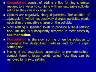
(1) Softening
Purpose: to remove metallic ions that cause hardness
(particularly Ca++ and Mg++)
Hardness:
Carbonate hardness : bicarbonate and carbonate salts.
[e.g. Ca(HCO3)2, CaCO3, Mg(HCO3)2, MgCO3].
Non-carbonate hardness : non-carbonate salts.
[e.g. CaSO4, CaCl2, MgSO4, MgCl2].
Types of Softening Processes
(1) Precipitation Softening (Lime-Soda Softening)
Lime, CaO: When slaked with water, Ca(OH)2 (lime slurry) is
formed:
CaO + H2O Ca(OH)2](https://image.slidesharecdn.com/2ksu-newcoagulationflocculation-230831051034-b1db5763/85/2_KSU-New_coagulation__flocculation-pdf-28-320.jpg)


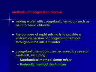
![Complete removal of hardness is not possible because of solubility limits of CaCO3
and Mg(OH)2 of about 40 mg/L as CaCO3 [30 mg/L of CaCO3 as CaCO3 + 10 mg/L of
Mg(OH)2 as CaCO3]. That is, a hardness of about 40 mg/L as CaCO3 remains in the
softened water.
Re-carbonation (addition of CO2 after lime treatment)
Stage One: CO2 is added to lower the pH to about 10.3 and convert the dissolved
excess lime into solid CaCO3:
Ca(OH)2 + CO2 CaCO3 + H2O
Stage Two: CO2 is added to reduce the pH to the range of 8.5 to 9.5 to convert most
of the remaining carbonate to bicarbonates:
CaCO3 + CO2 + H2O Ca(HCO3)2](https://image.slidesharecdn.com/2ksu-newcoagulationflocculation-230831051034-b1db5763/85/2_KSU-New_coagulation__flocculation-pdf-32-320.jpg)


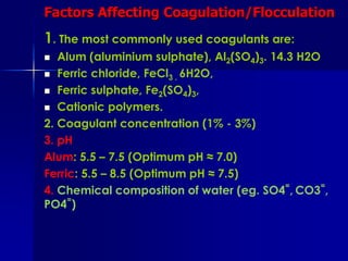
![Meq/l bar graph for the raw water before treatment
Components MEQ/L Application Lime Soda Ash
Equation Meq/l Meq/l
CO2 0.40 7-15 0.40 0
Ca(HCO3)2 2.00 7-16 2.00 0
Mg(HCO3)2 0.70 7-17 1.40 0
MgSO4 0.51 7-18 & 7-19 0.51 0.51
4.31 0.51
Lime dosage = stoichiometric quantity + excess lime (35 mg/l CaO)
= 4.31 X 28 + 35 = 156 MG/L CaO
[note: eq. wt of CaO = (40 + 16) / 2 = 28]
Soda ash dosage = 0.51 x 53 = 27 mg/l Na2 CO3
[note: eq. wt. of Na2CO3 = (23 x 2 + 12 + 16 x 3) / 2 = 106/2 = 53]
0.0 2.00 3.21 3.81
CO2 Ca++
Mg++
Na+
0.4 HCO3
- SO4=
Cl-
0.0 2.70 3.3 3.81
0.0 2.00 3.21 3.81
CO2 Ca++
Mg++
Na+
0.4 HCO3
- SO4=
Cl-
0.0 2.70 3.3 3.81](https://image.slidesharecdn.com/2ksu-newcoagulationflocculation-230831051034-b1db5763/85/2_KSU-New_coagulation__flocculation-pdf-37-320.jpg)


