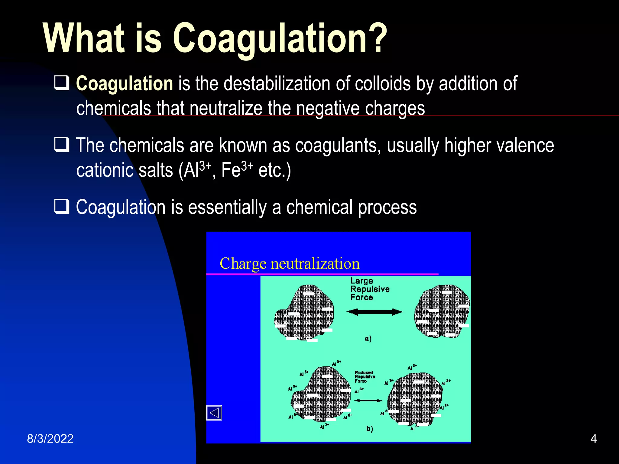
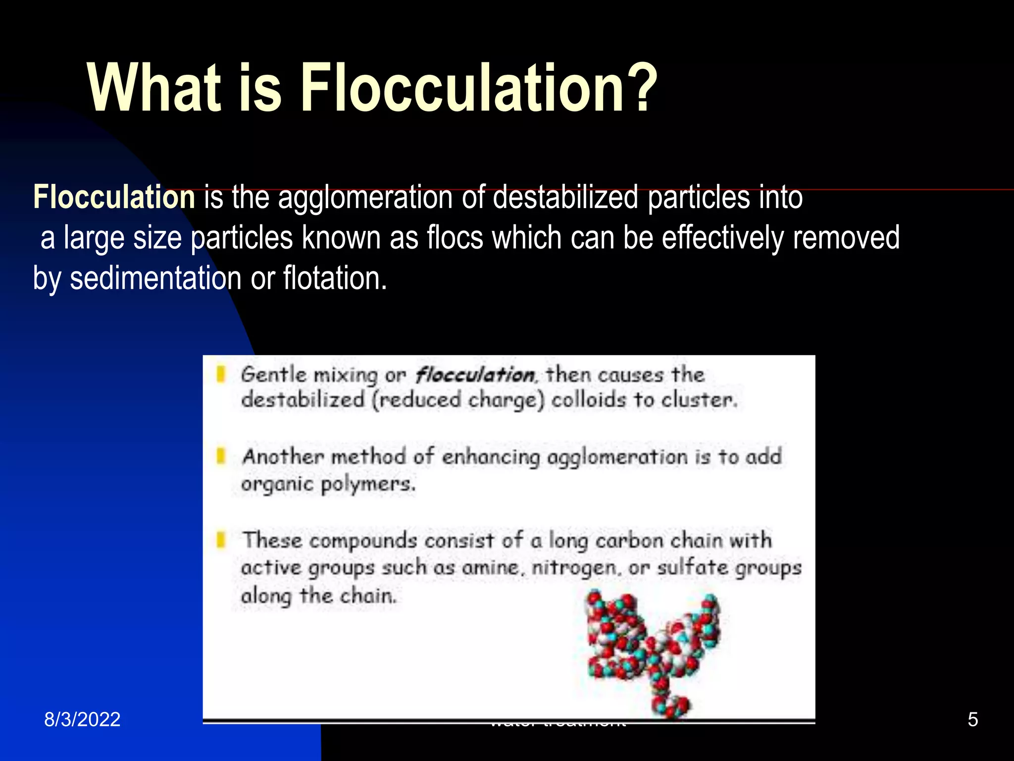
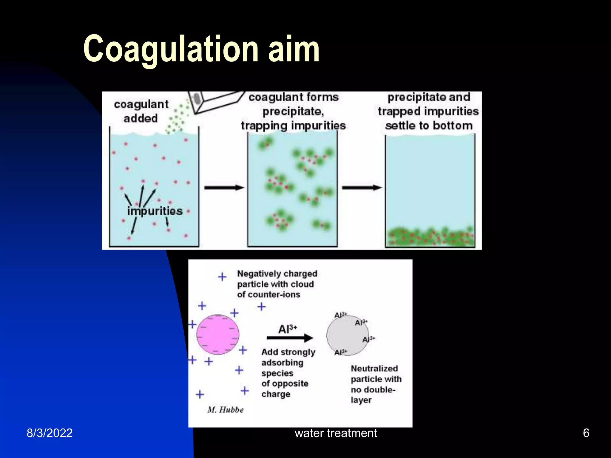
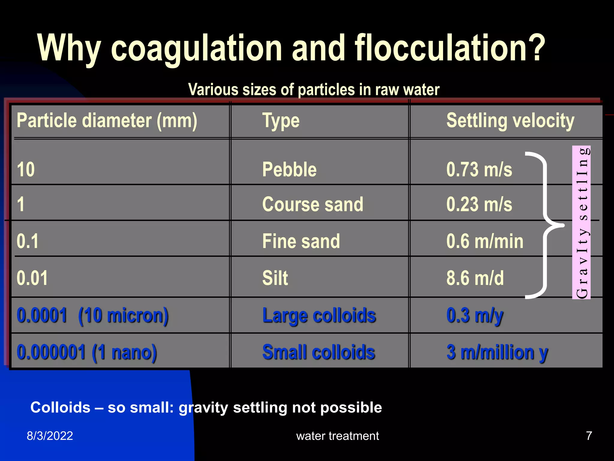
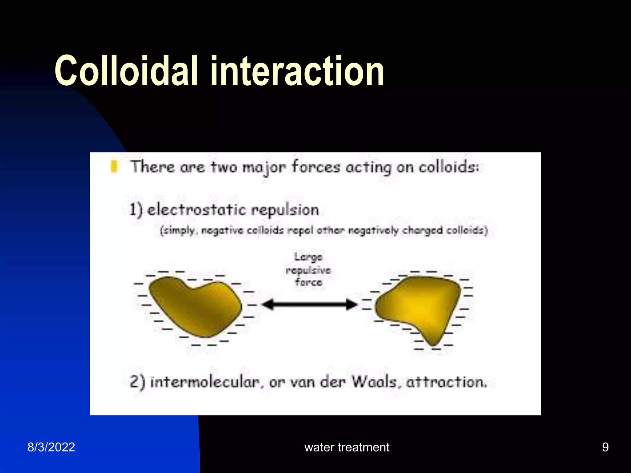
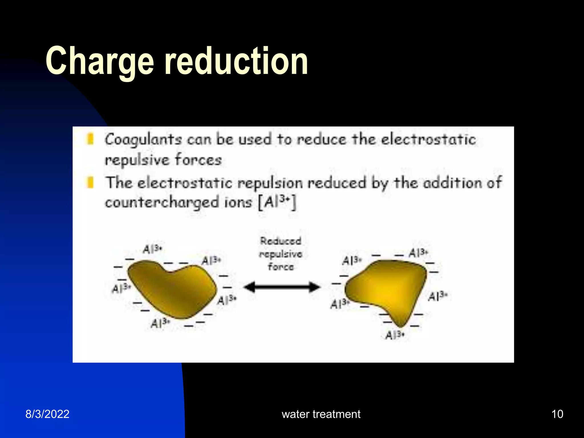
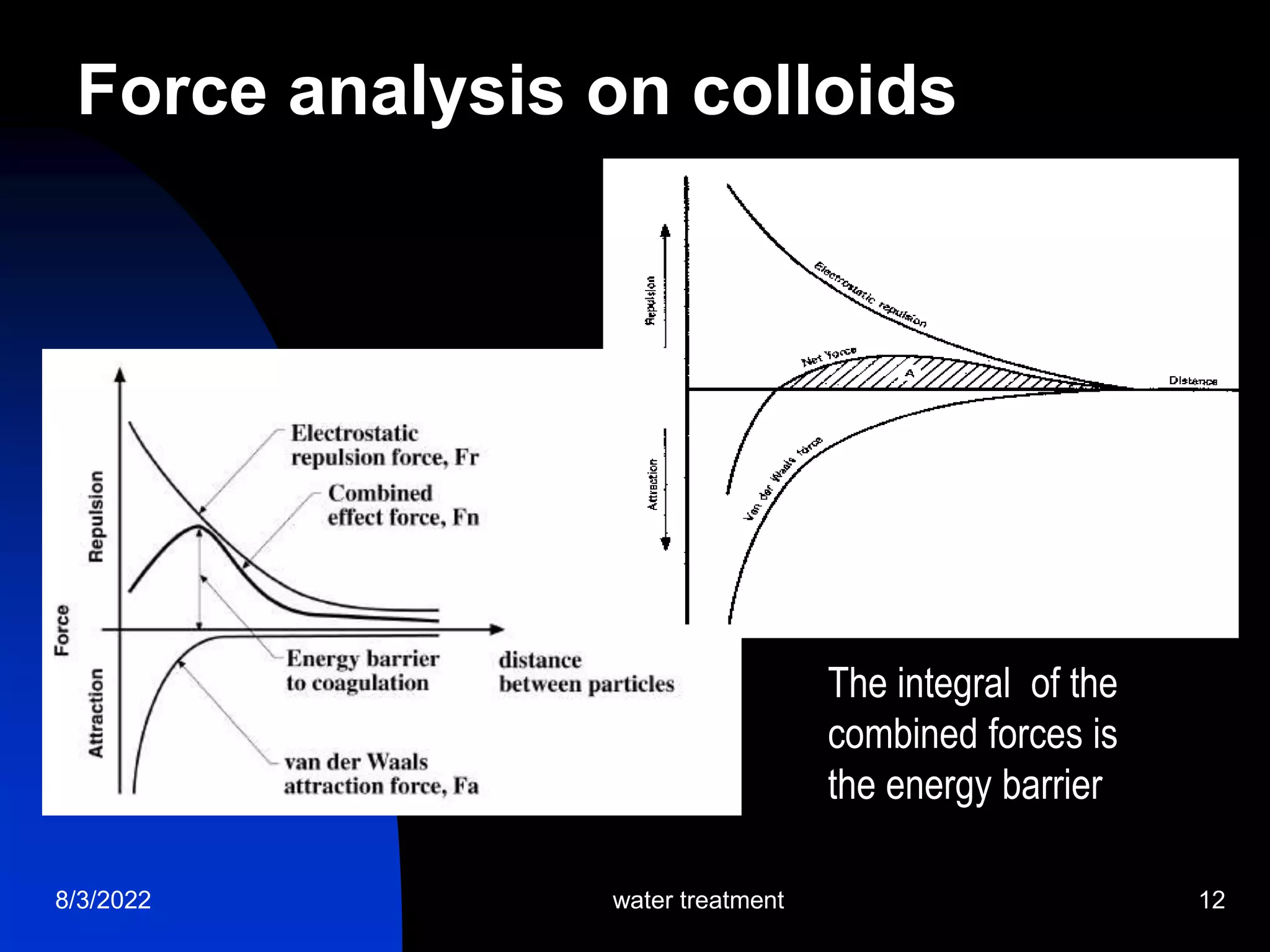
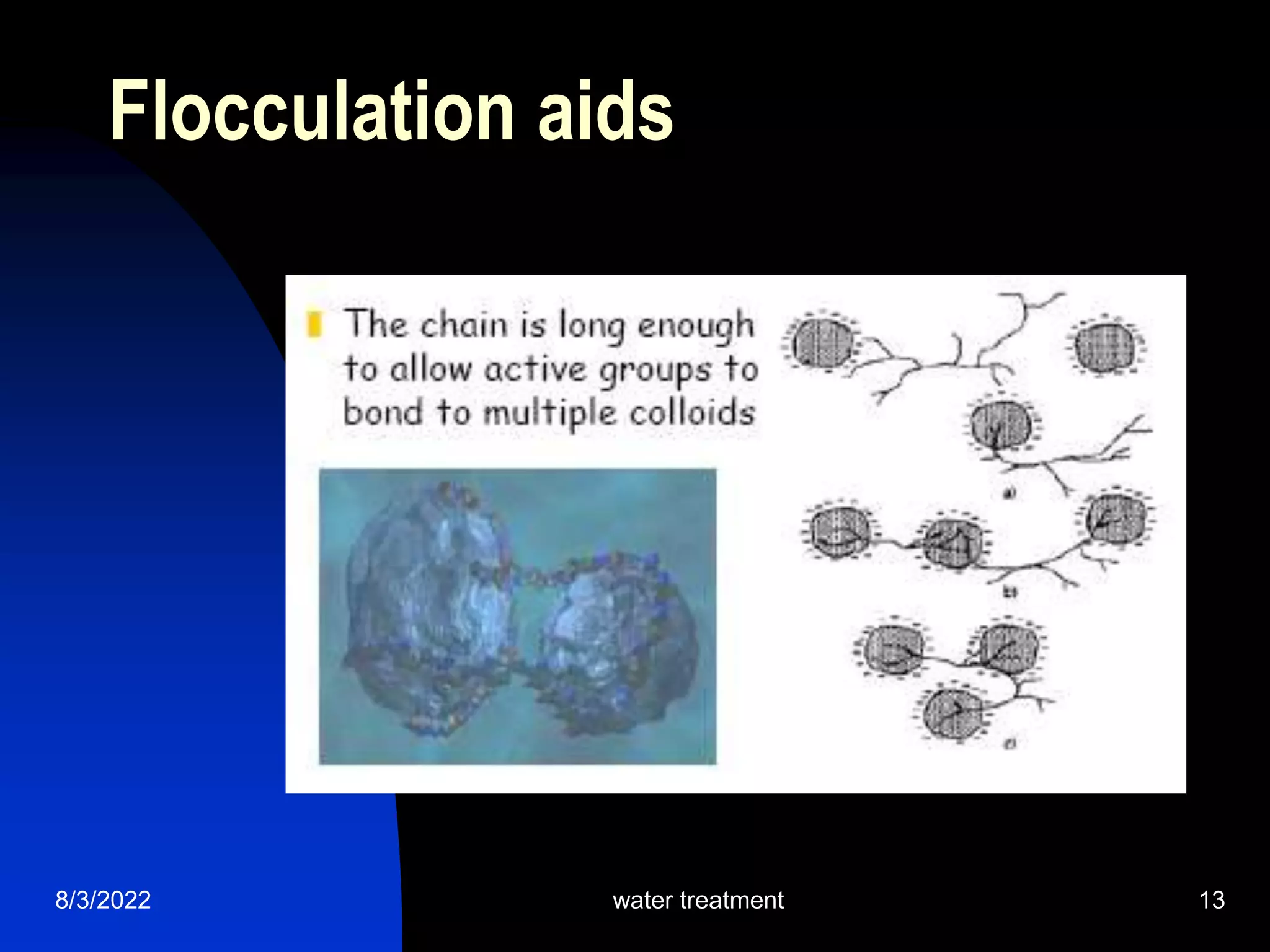
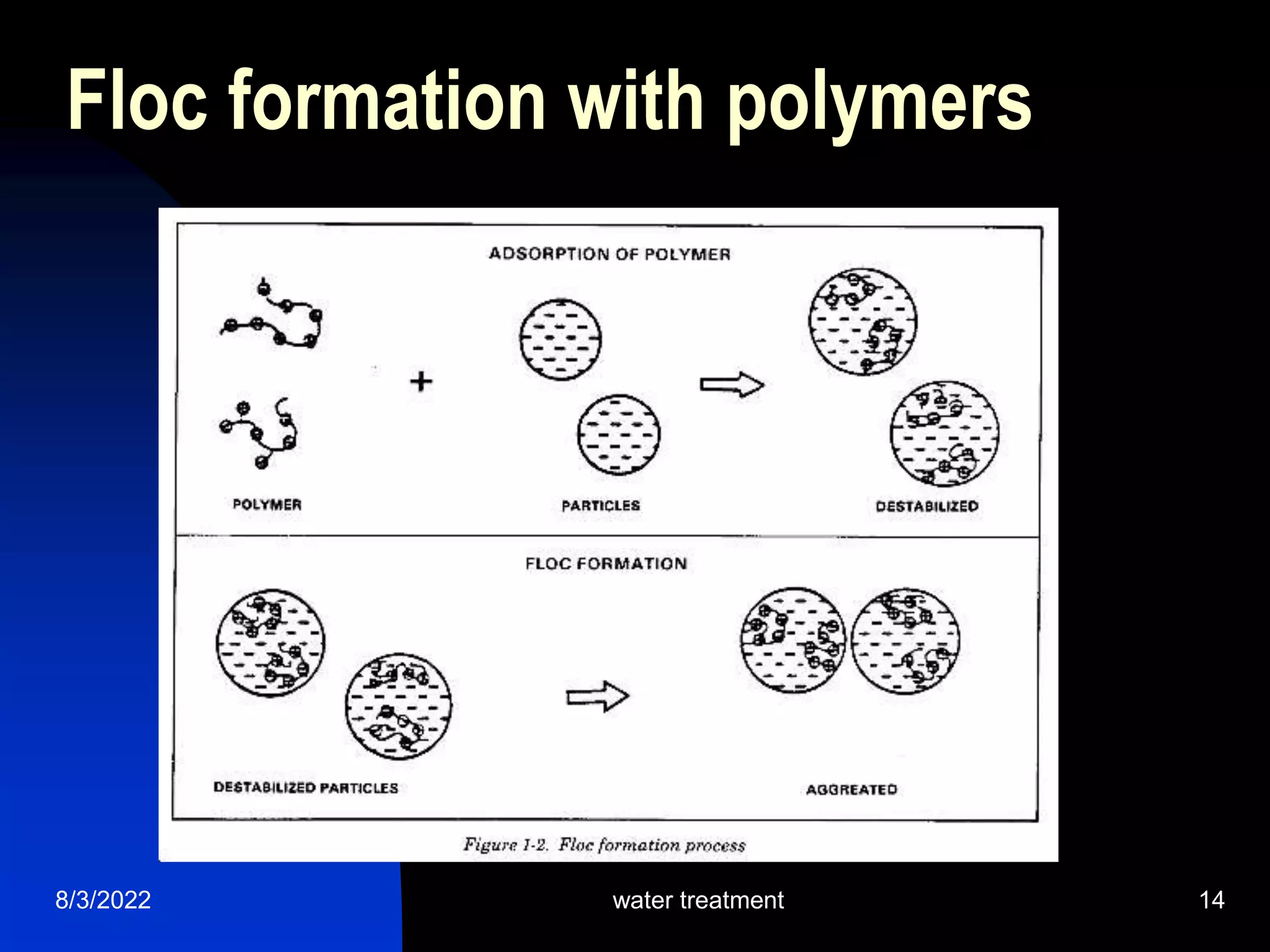
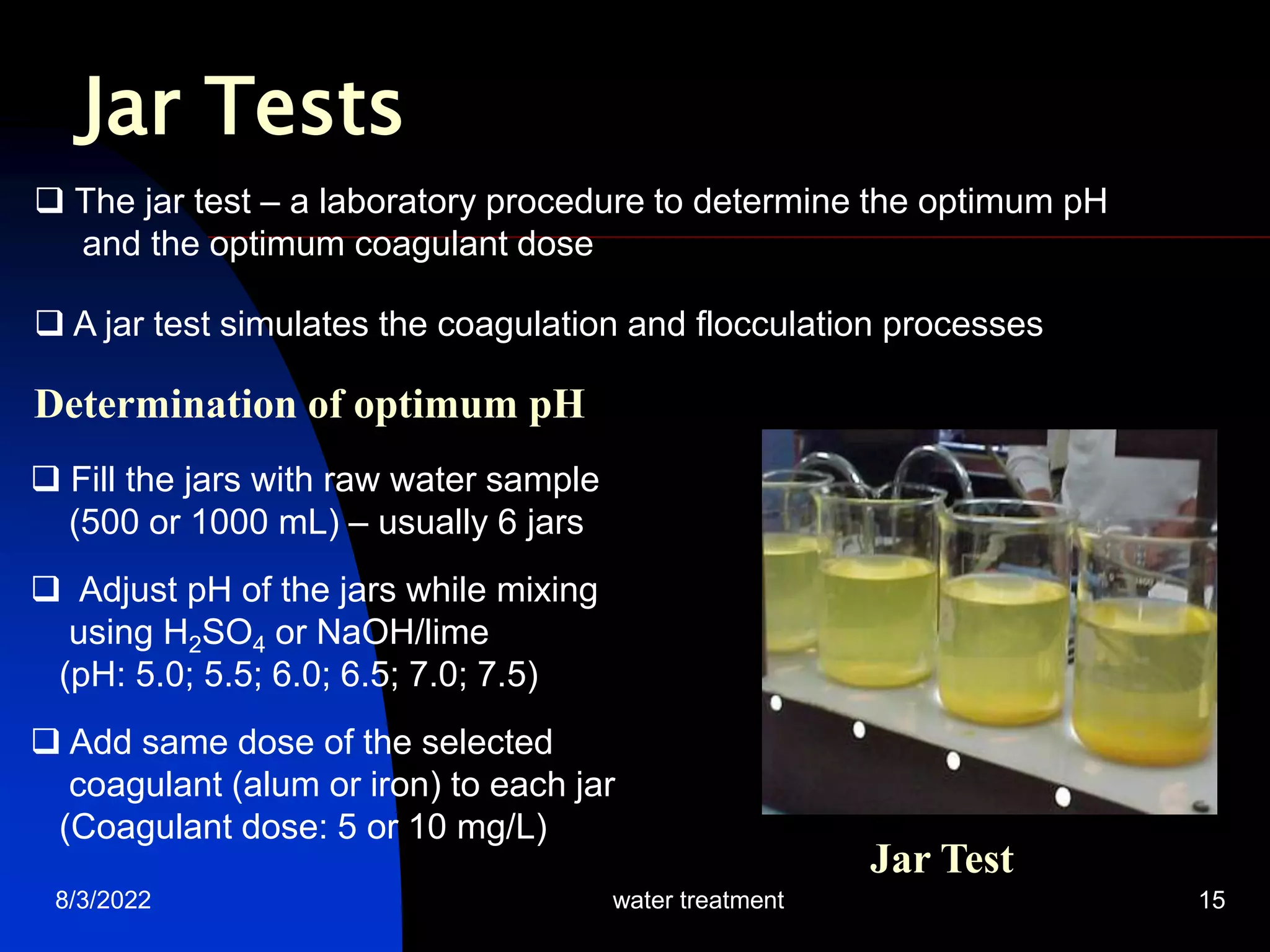
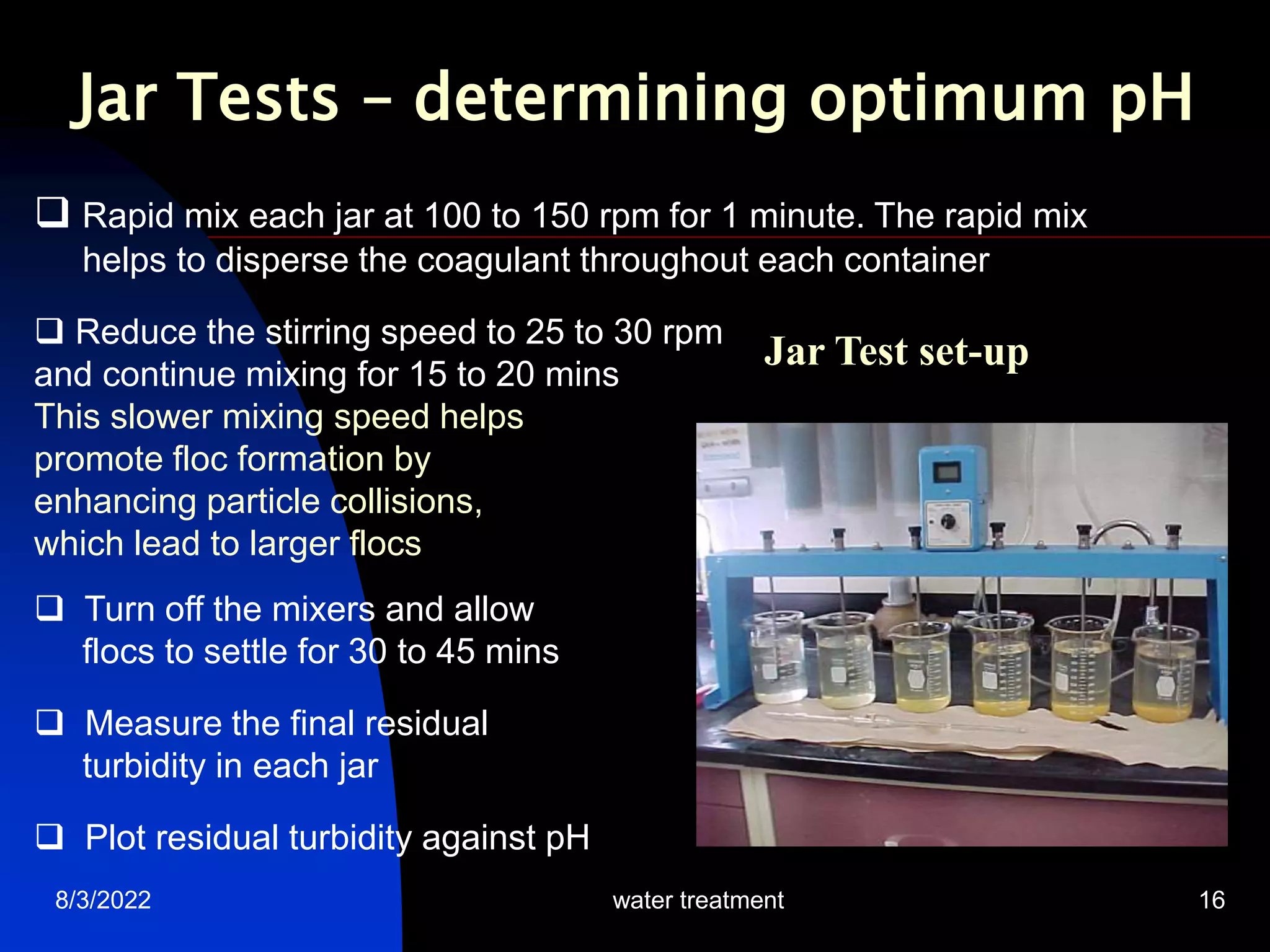
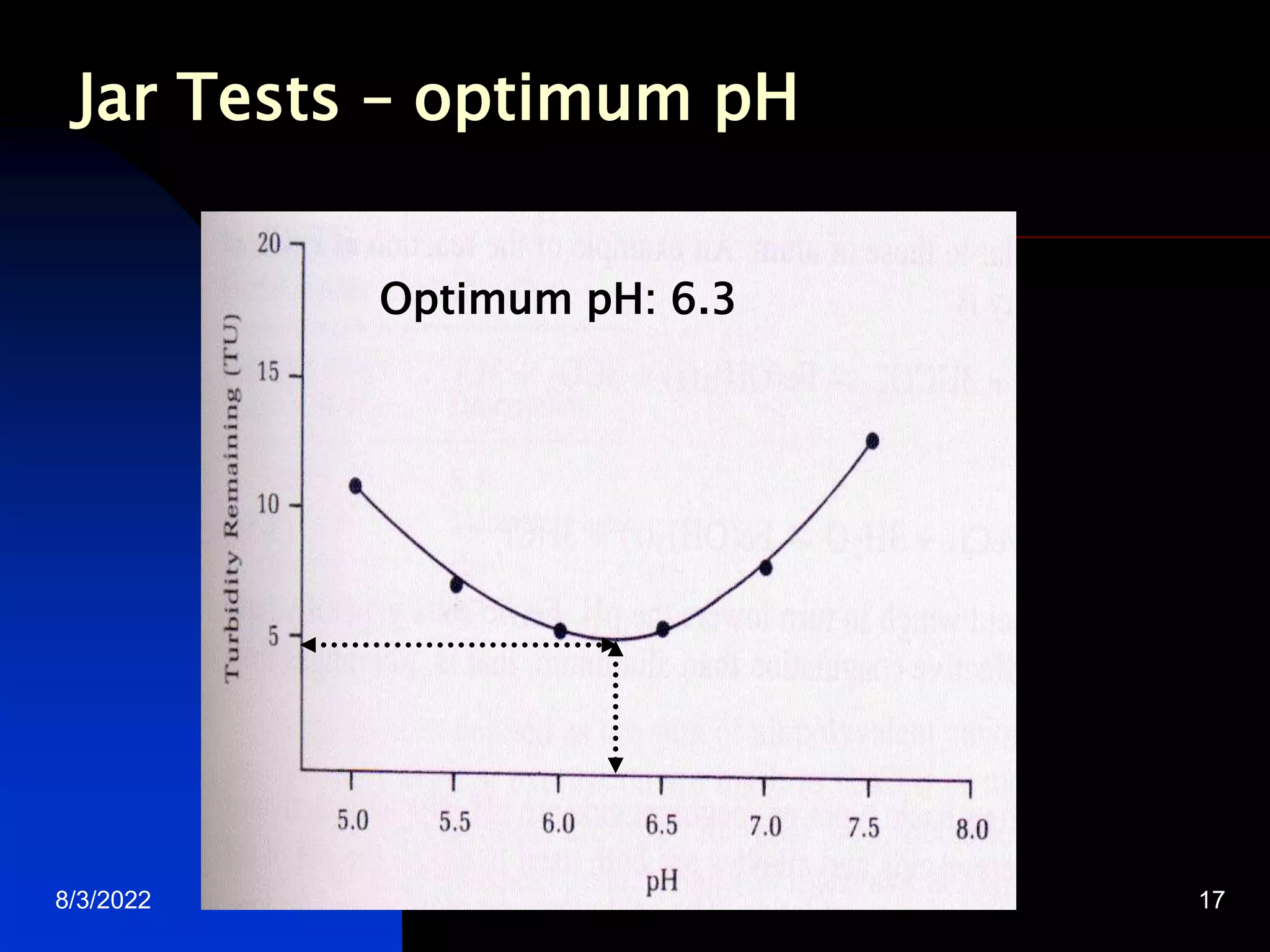
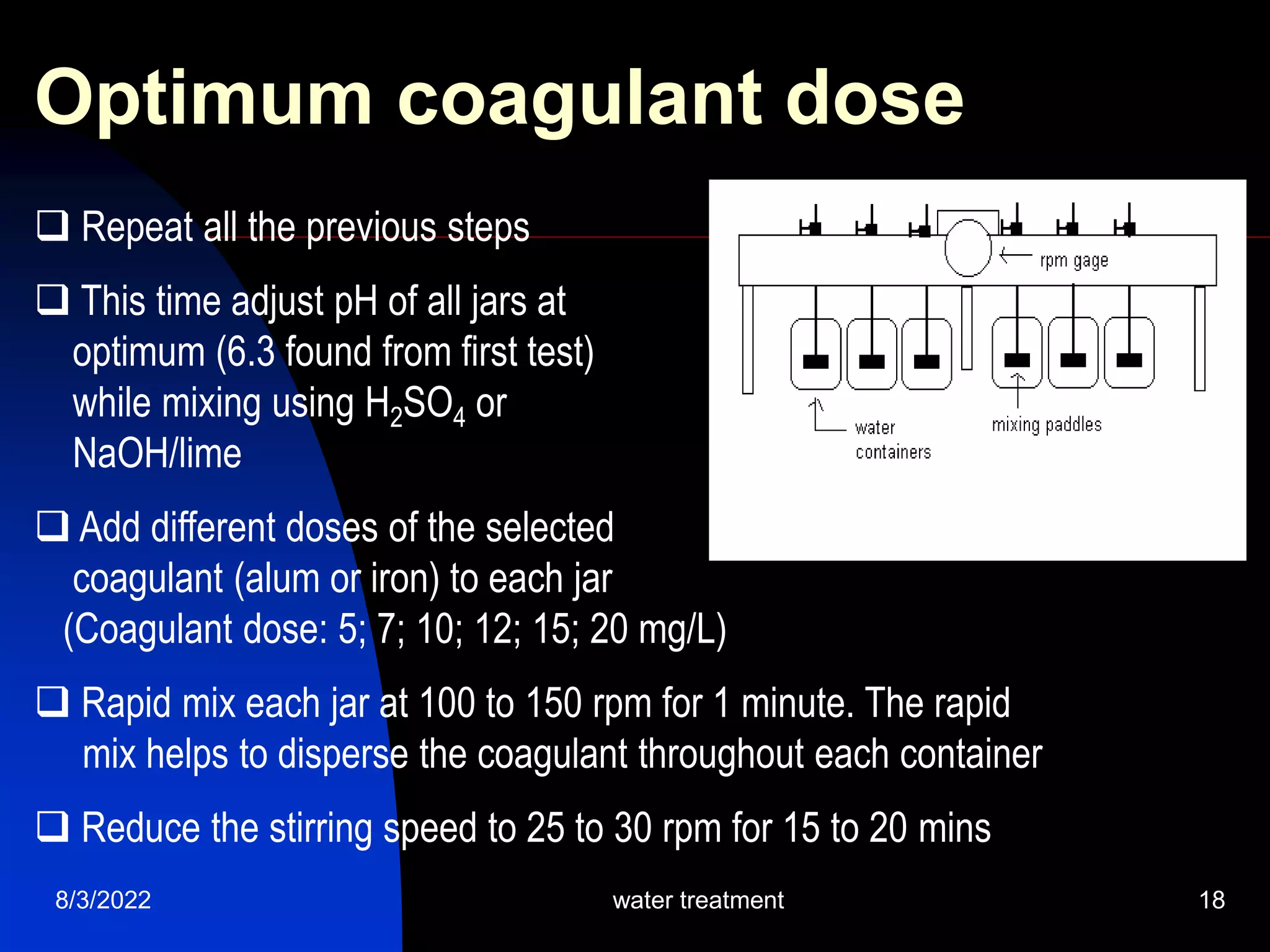
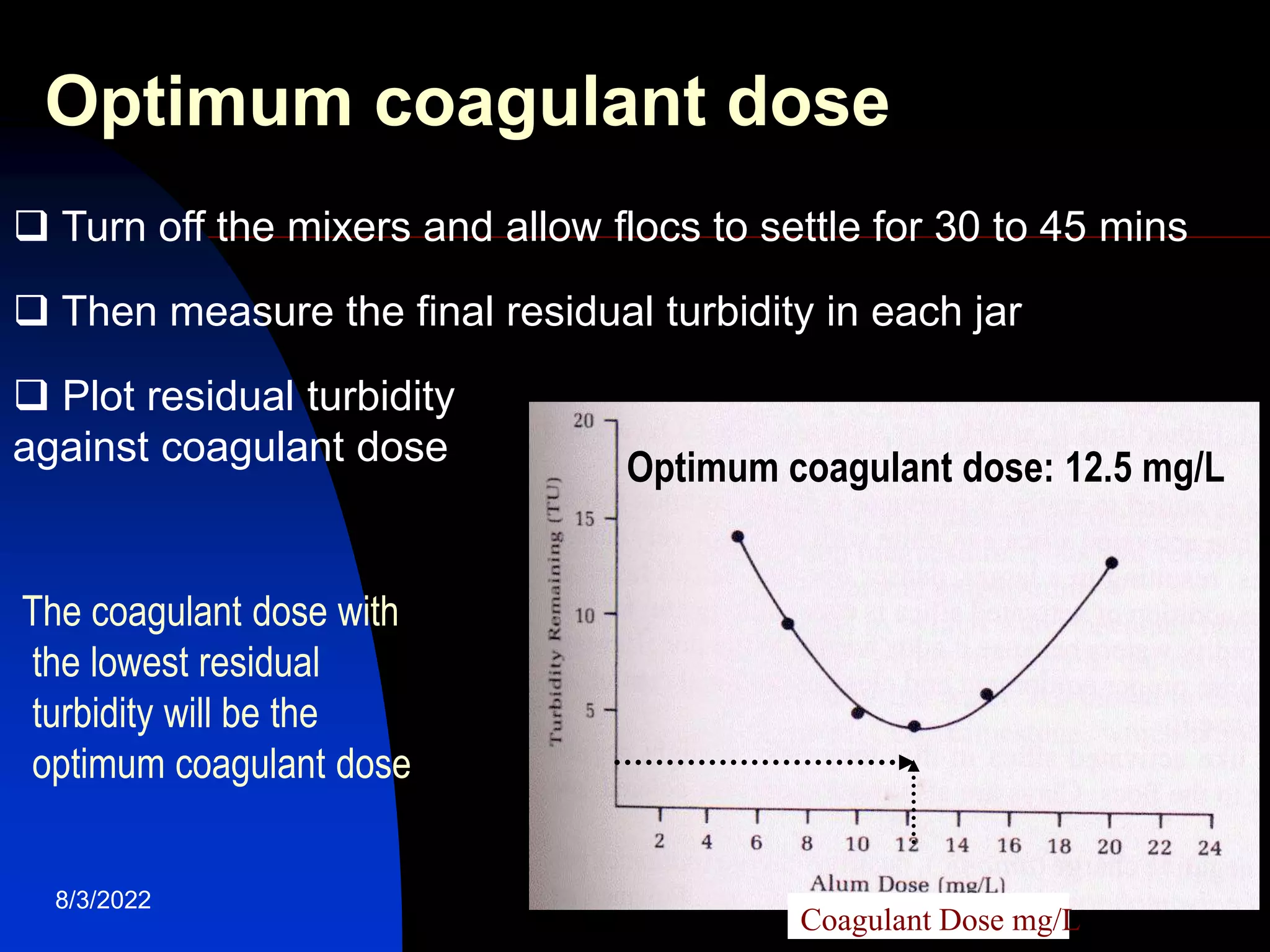
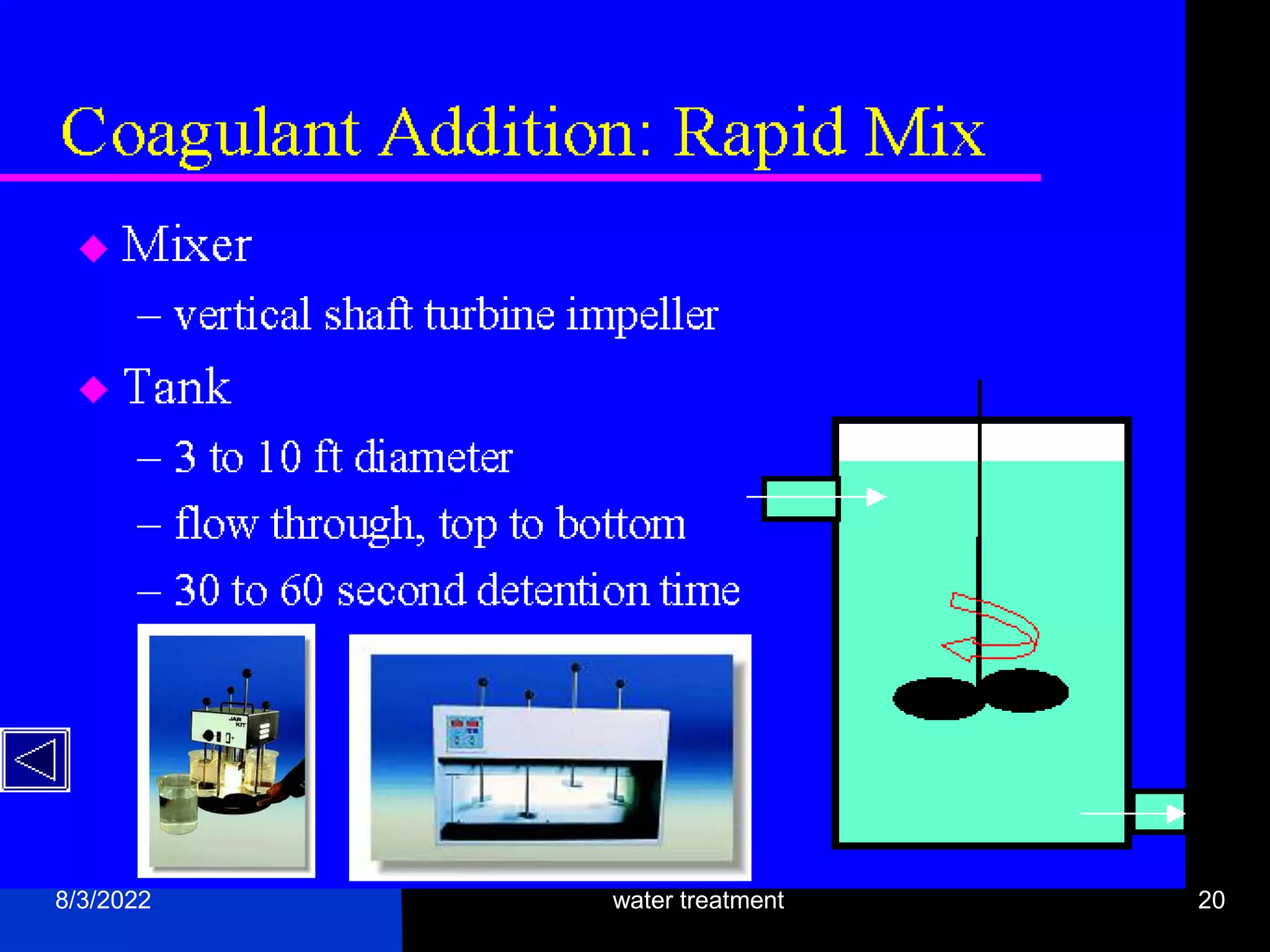
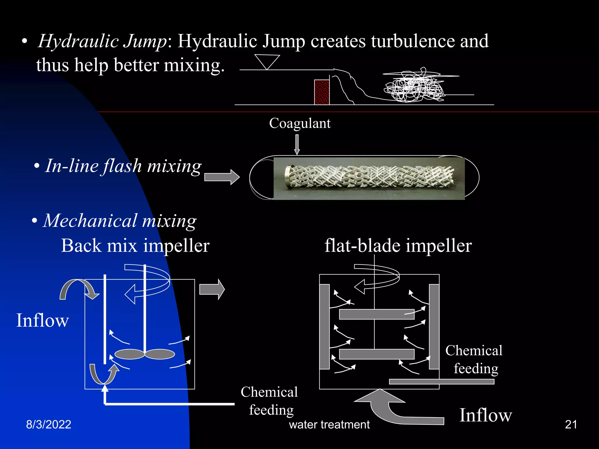
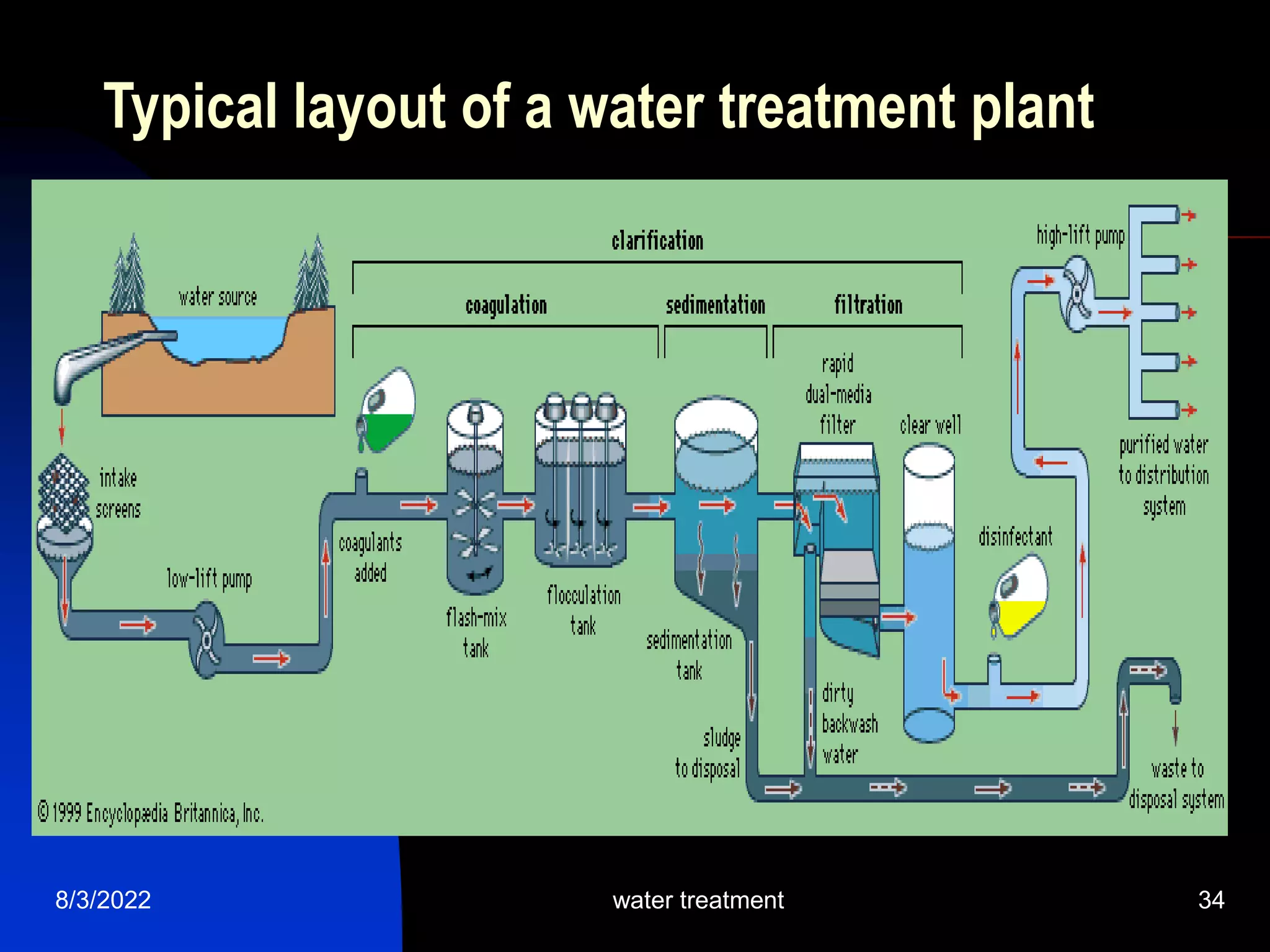
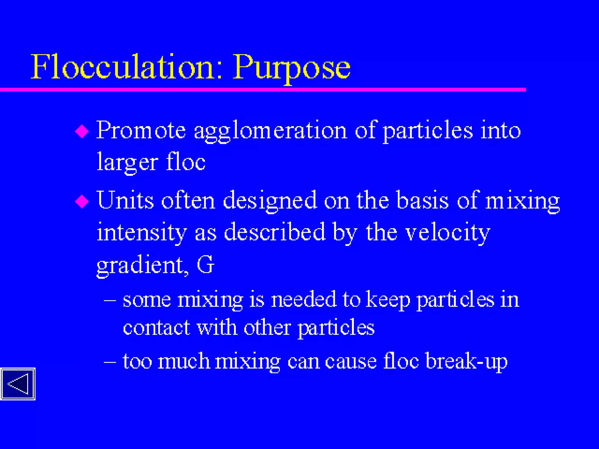
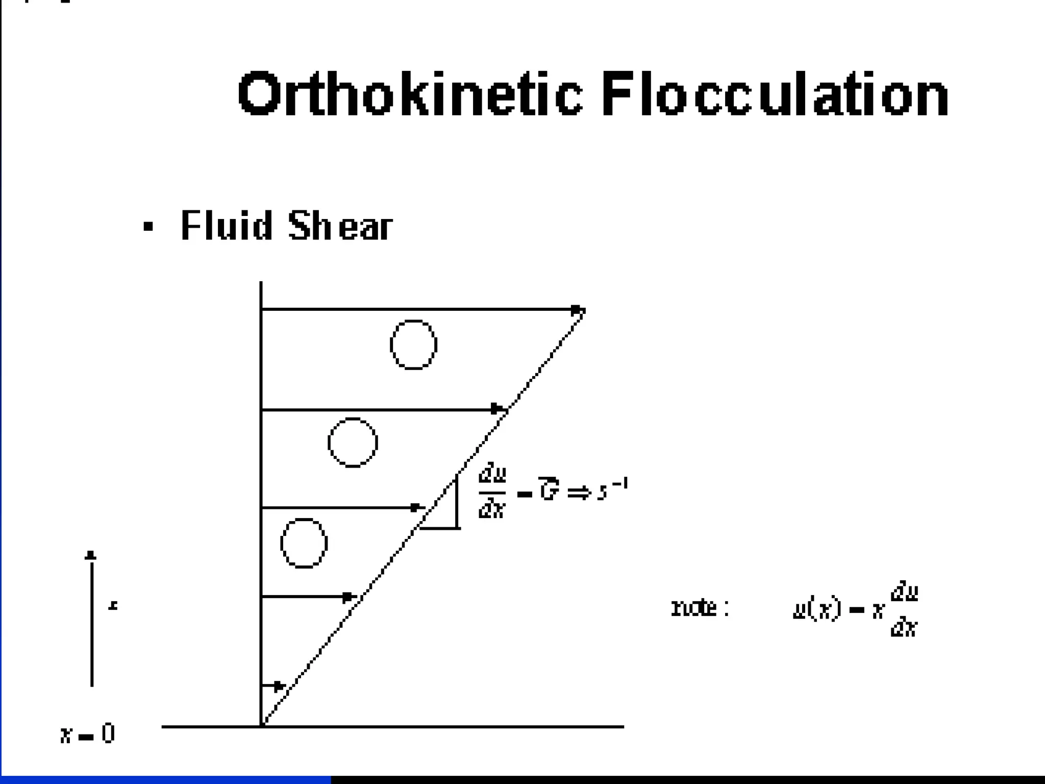
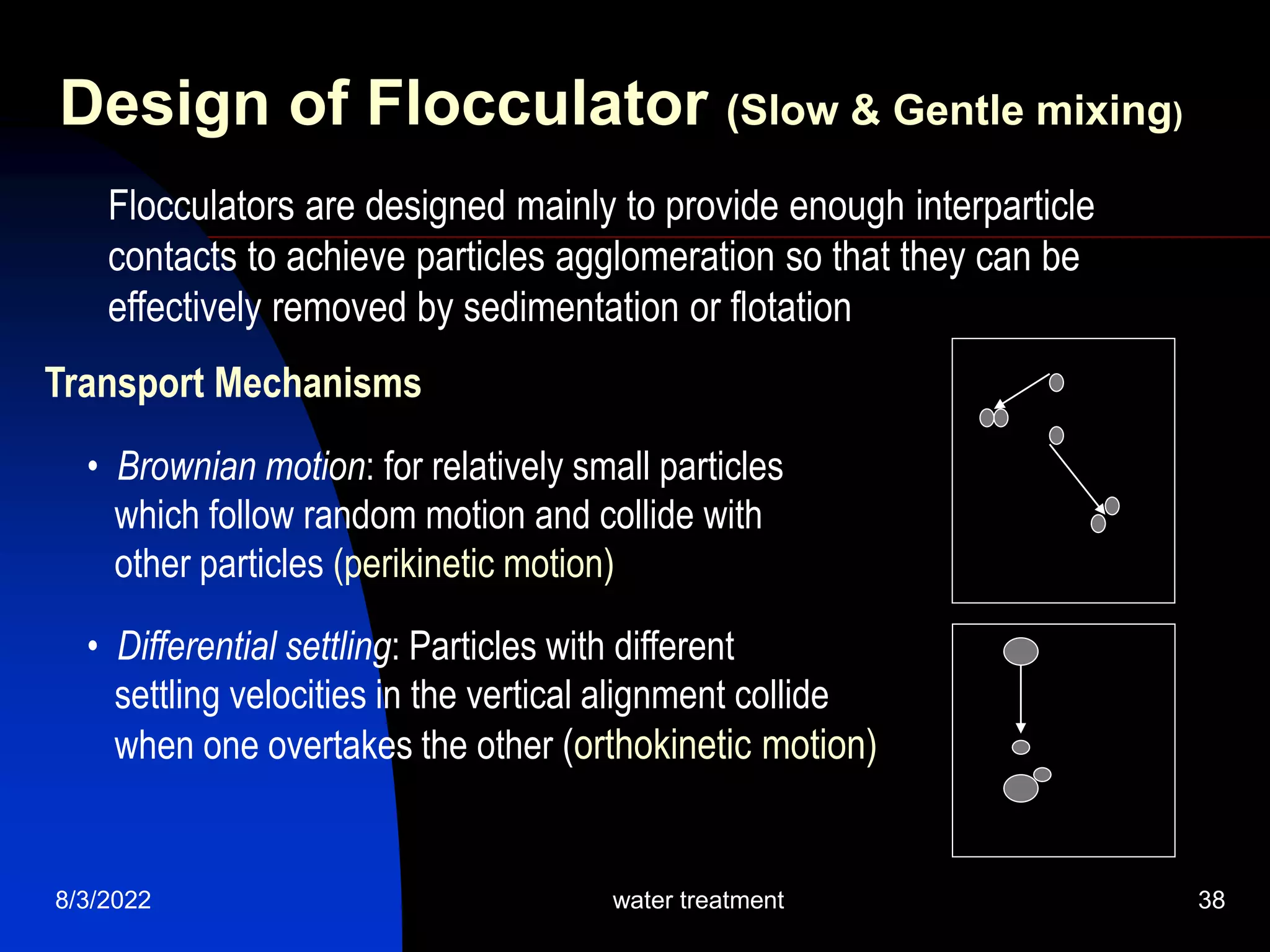
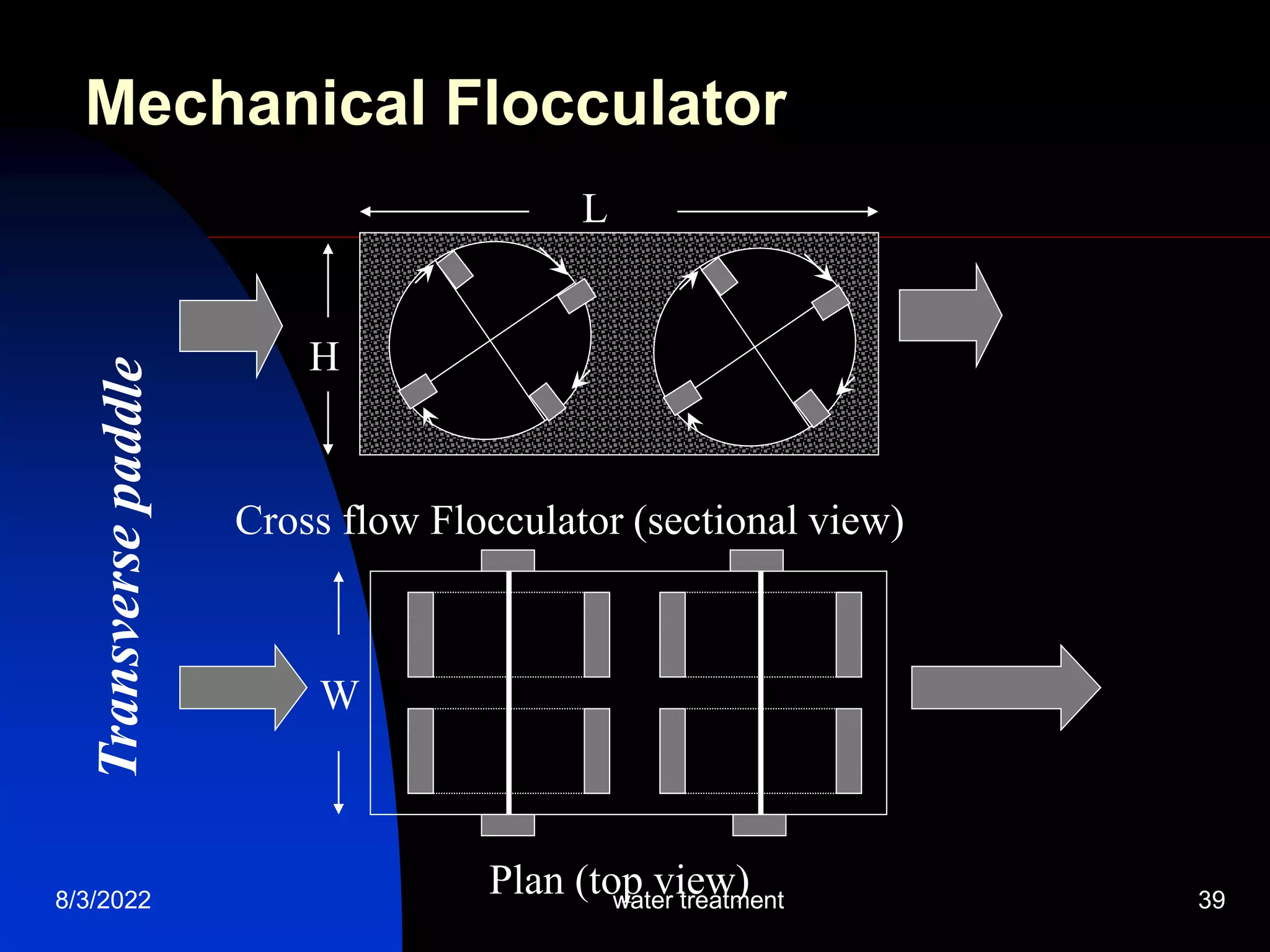
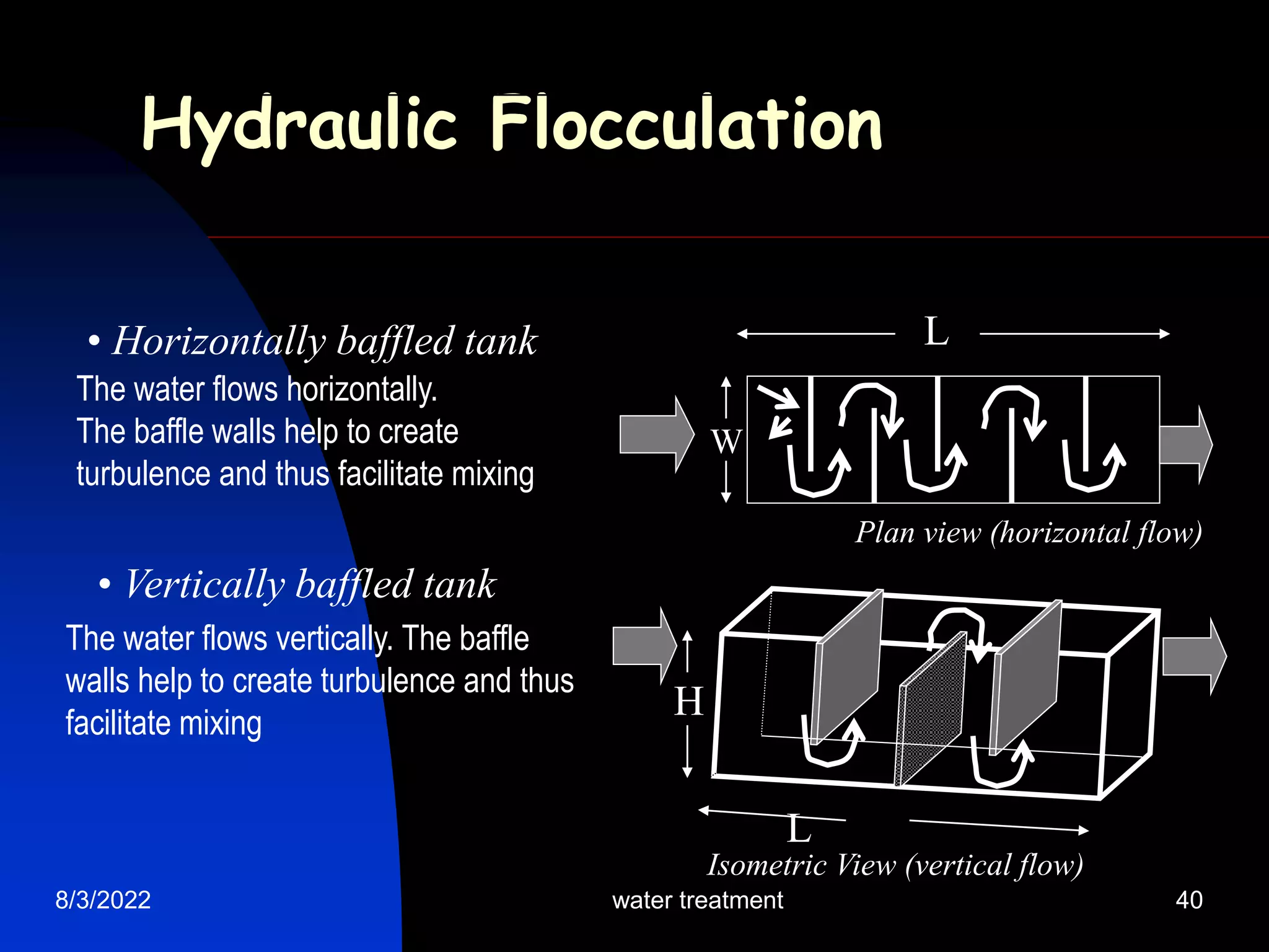
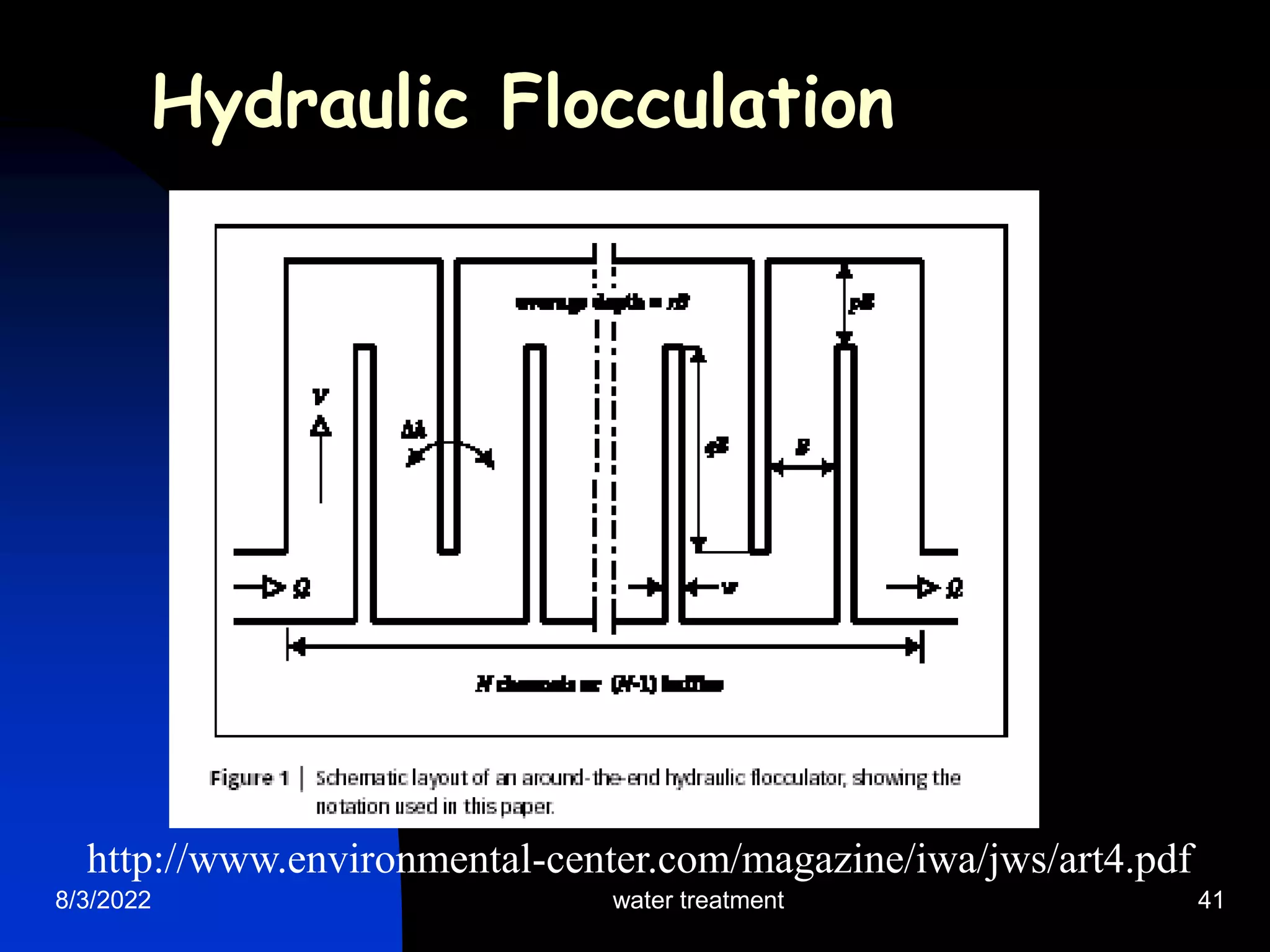
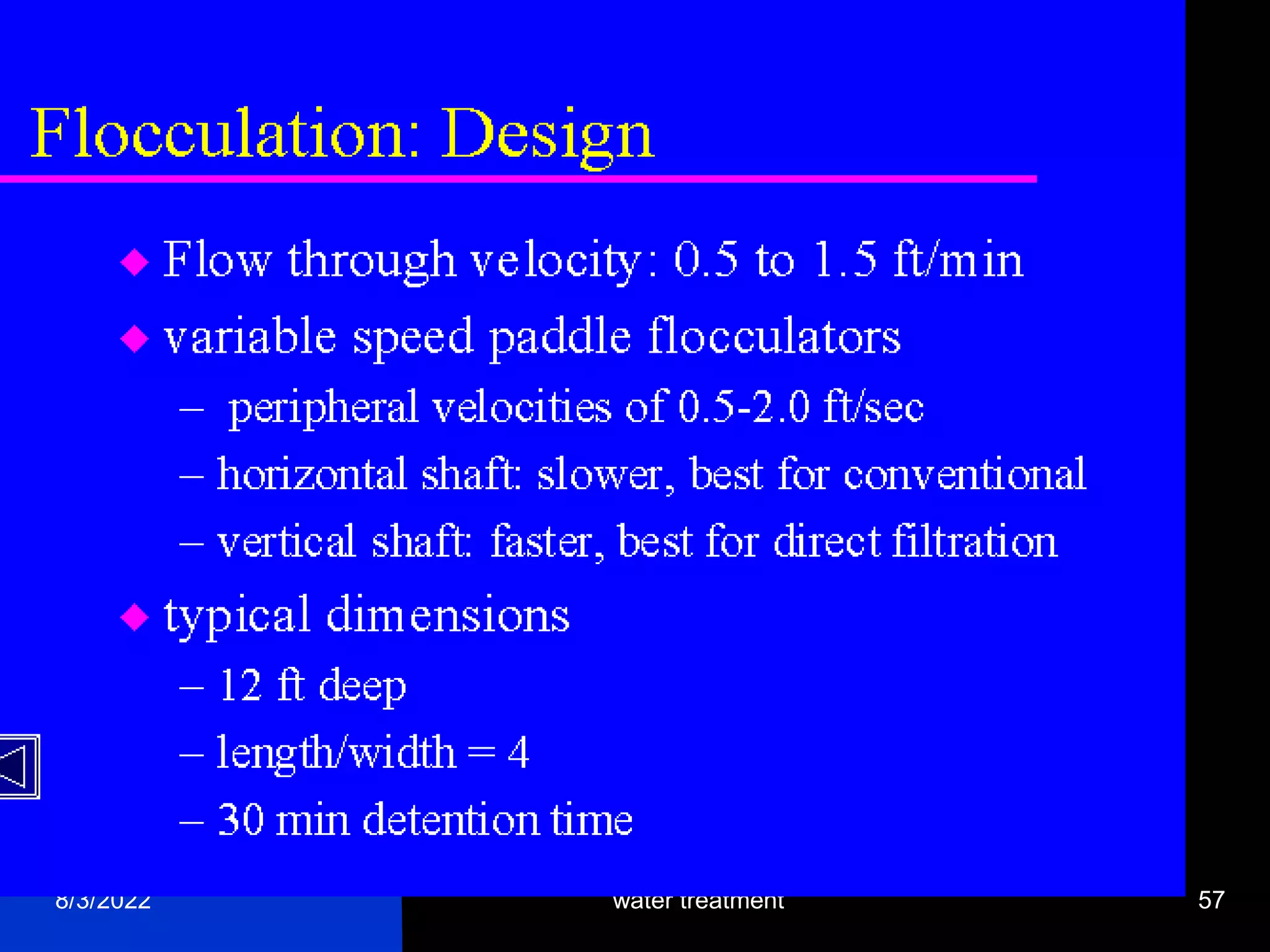
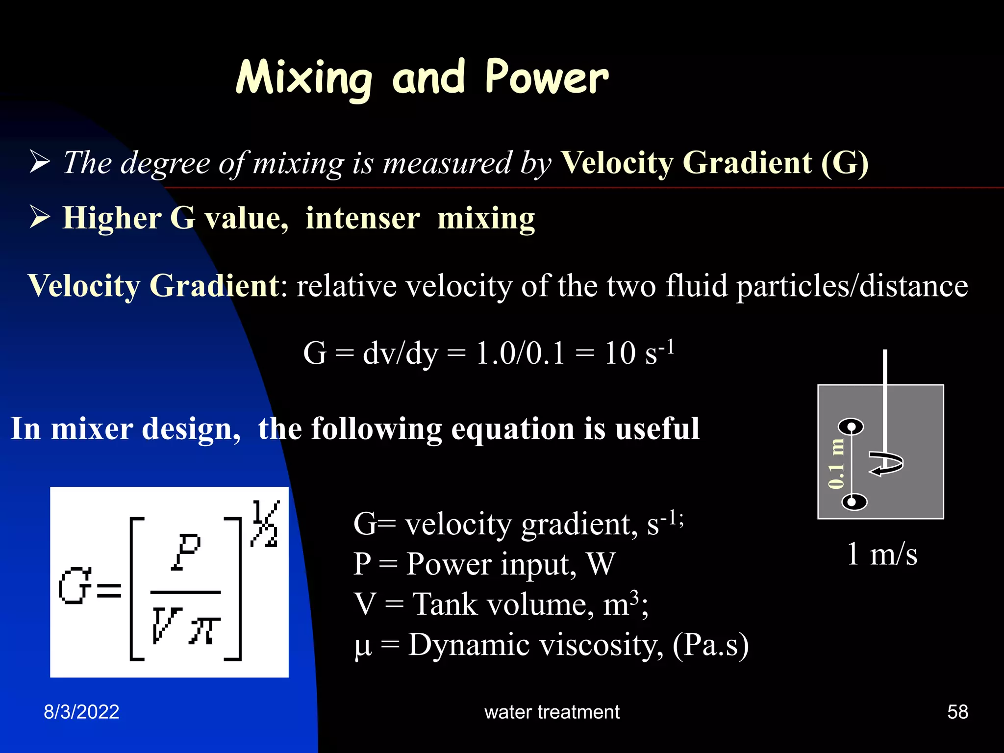
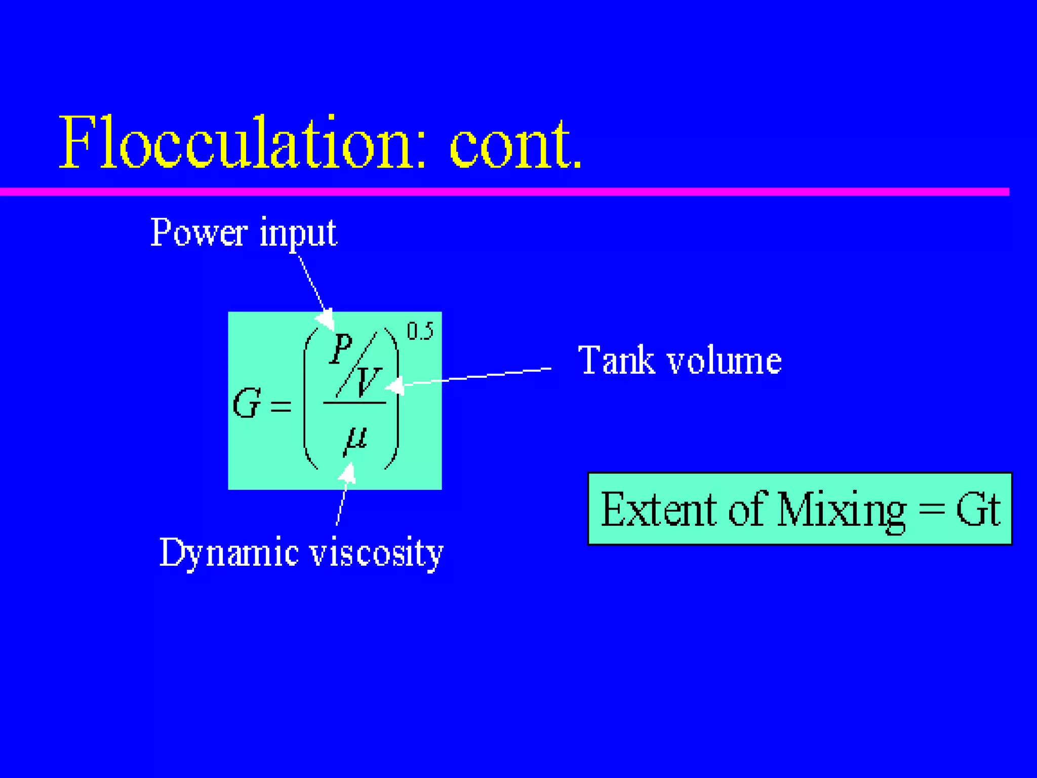
8/3/2022 water treatment 1
Coagulation and
Flocculation in
Water Treatment
J(Hans) van Leeuwen
8/3/2022 water treatment 2
Introduction
The need to clarify water
 Aesthetics and health
 Colloids – impart color and turbidity
to water – aesthetical acceptability
 Microbes are colloids too
8/3/2022 water treatment 3
COAGULATION &
FLOCCULATION
 Removal of colloidal
substances from water
 Potable water requirements
 health, aesthetics, economic
 Colloids
 Size of colloids - light waves
 Brownian motion
 Stability of colloids
8/3/2022 water treatment 4
What is Coagulation?
 Coagulation is the destabilization of colloids by addition of
chemicals that neutralize the negative charges
 The chemicals are known as coagulants, usually higher valence
cationic salts (Al3+, Fe3+ etc.)
 Coagulation is essentially a chemical process
--
-
-
-
-
- --
-
-
-
-
-
--
-
-
-
-
- --
-
-
-
-
-
8/3/2022 water treatment 5
What is Flocculation?
Flocculation is the agglomeration of destabilized particles into
a large size particles known as flocs which can be effectively removed
by sedimentation or flotation.
Coagulation aim
8/3/2022 water treatment 6
8/3/2022 water treatment 7
Why coagulation and flocculation?
Various sizes of particles in raw water
Particle diameter (mm) Type Settling velocity
10 Pebble 0.73 m/s
1 Course sand 0.23 m/s
0.1 Fine sand 0.6 m/min
0.01 Silt 8.6 m/d
0.0001 (10 micron) Large colloids 0.3 m/y
0.000001 (1 nano) Small colloids 3 m/million y
Colloids – so small: gravity settling not possible
G
r
a
v
I
t
y
s
e
t
t
l
I
n
g
8/3/2022 water treatment 8
Colloid Stability
---
-
-
- ---
-
-
-
Repulsion
Colloid - A Colloid - B
 Colloids have a net negative surface charge
 Electrostatic force prevents them from agglomeration
 Brownian motion keeps the colloids in suspension
H2O
Colloid
 Impossible to remove colloids by gravity settling
Colloidal interaction
8/3/2022 water treatment 9
Charge reduction
8/3/2022 water treatment 10
8/3/2022 water treatment 11
 Colloids can be destabilized by charge
neutralization
 Positively charges ions (Na+, Mg2+, Al3+,
Fe3+ etc.) neutralize the colloidal negative
charges and thus destabilize them.
 With destabilization, colloids aggregate in
size and start to settle
Colloid Destabilization
8/3/2022 water treatment 12
Force analysis on colloids
The integral of the
combined forces is
the energy barrier
Flocculation aids
8/3/2022 water treatment 13
Floc formation with polymers
8/3/2022 water treatment 14
8/3/2022 water treatment 15
Jar Tests
Determination of optimum pH
 The jar test – a laboratory procedure to determine the optimum pH
and the optimum coagulant dose
 A jar test simulates the coagulation and flocculation processes
 Fill the jars with raw water sample
(500 or 1000 mL) – usually 6 jars
 Adjust pH of the jars while mixing
using H2SO4 or NaOH/lime
(pH: 5.0; 5.5; 6.0; 6.5; 7.0; 7.5)
 Add same dose of the selected
coagulant (alum or iron) to each jar
(Coagulant dose: 5 or 10 mg/L)
Jar Test
8/3/2022 water treatment 16
Jar Test set-up
 Rapid mix each jar at 100 to 150 rpm for 1 minute. The rapid mix
helps to disperse the coagulant throughout each container
 Reduce the stirring speed to 25 to 30 rpm
and continue mixing for 15 to 20 mins
This slower mixing speed helps
promote floc formation by
enhancing particle collisions,
which lead to larger flocs
 Turn off the mixers and allow
flocs to settle for 30 to 45 mins
 Measure the final residual
turbidity in each jar
 Plot residual turbidity against pH
Jar Tests – determining optimum pH
8/3/2022 water treatment 17
Optimum pH: 6.3
Jar Tests – optimum pH
8/3/2022 water treatment 18
Optimum coagulant dose
 Repeat all the previous steps
 This time adjust pH of all jars at
optimum (6.3 found from first test)
while mixing using H2SO4 or
NaOH/lime
 Add different doses of the selected
coagulant (alum or iron) to each jar
(Coagulant dose: 5; 7; 10; 12; 15; 20 mg/L)
 Rapid mix each jar at 100 to 150 rpm for 1 minute. The rapid
mix helps to disperse the coagulant throughout each container
 Reduce the stirring speed to 25 to 30 rpm for 15 to 20 mins
8/3/2022 water treatment 19
 Turn off the mixers and allow flocs to settle for 30 to 45 mins
 Then measure the final residual turbidity in each jar
 Plot residual turbidity
against coagulant dose
Coagulant Dose mg/L
Optimum coagulant dose: 12.5 mg/L
The coagulant dose with
the lowest residual
turbidity will be the
optimum coagulant dose
Optimum coagulant dose
8/3/2022 water treatment 20
8/3/2022 water treatment 21
• Hydraulic Jump: Hydraulic Jump creates turbulence and
thus help better mixing.
• Mechanical mixing
• In-line flash mixing
Inflow
Chemical
feeding
Chemical
feeding
Inflow
Back mix impeller flat-blade impeller
Coagulant
8/3/2022 water treatment 22
8/3/2022 water treatment 23
8/3/2022 water treatment 24
Inflow
Chemical
feeding
Inflow
Chemical
feeding
8/3/2022 water treatment 25
8/3/2022 water treatment 26
 Relative coagulating power
Na+ = 1; Mg2+ = 30
Al3+ > 1000; Fe3+ > 1000
 Typical coagulants
Aluminum sulfate: Al2(SO4)3.14 H2O
Iron salt- Ferric sulfate: Fe2(SO4)3
Iron salt- Ferric chloride: Fe2Cl3
Polyaluminum chloride (PAC): Al2(OH)3Cl3
8/3/2022 water treatment 27
Aluminum Chemistry
1 mole of alum consumes 6 moles of bicarbonate (HCO3
-)
Al2(SO4)3.14 H2O + 6HCO3
-  2Al(OH)3+ 6CO2 + 14H2O + 3SO4
-2
If alkalinity is not enough, pH will reduce greatly
Lime or sodium carbonate may be needed to neutralize the acid.
(Optimum pH: 5.5 – 6.5)
With alum addition, what happens to water pH?
Al2(SO4)3.14 H2O  2Al(OH)3+ 8H2O + 3H2SO4
-2
Al3+ species as a function of pH
8/3/2022 water treatment 28
8/3/2022 water treatment 29
Alkalinity calculation
Al2(SO4)3.14 H2O + 6HCO3
-  2Al(OH)3+ 6CO2 + 14H2O + 3SO4
-2
594 mg 366 mg
If 200 mg/L of alum to be added to achieve complete coagulation.
How much alkalinity is consumed in mg/L as CaCO3?
594 mg alum consumes 366 mg HCO3
-
200 mg alum will consume (366/594) x 200 mg HCO3
-
= 123 mg HCO3
-
Alkalinity in mg/L as CaCO3 = 123 x (50/61)
= 101 mg/L as CaCO3
8/3/2022 water treatment 30
Iron Chemistry
FeCl3+ 3HCO3
-  Fe(OH)3+ 3CO2 + 3Cl-
With iron salt addition, what happens to water pH?
(Wider pH range of: 4 – 9; Best pH range of 4.5 – 5.5)
1 mole of FeCl3 consumes 3 moles of bicarbonate (HCO3
-)
If alkalinity is not enough, pH will reduce greatly due to hydrochloric
acid formation. Lime or sodium carbonate may be needed to neutralize
the acid. Lime is the cheapest.
If 200 mg/L of ferric chloride is added for coagulation, how
much alkalinity is consumed in mg/L as CaCO3?
Exercise: Alkalinity calculation
Fe species as a function of pH
8/3/2022 water treatment 31
8/3/2022 water treatment 32
COAGULANT AIDS
Other substances than
coagulants used:
- Clay minerals
- Silicates
- Polymers
Polymers are often
either anionic or
cationic to aid
coagulation.
Polymers also
reinforce flocs
8/3/2022 water treatment 33
FLOCCULATION
Flocculation - agglomeration of colloids by collisions to form separable flocs
Examples - milk, blood, seawater
Mechanisms - perikinetic, collisions from Brownian motion
- orthokinetic, induced collisions through stirring
Orthokinetic flocculation
Velocity gradient, relative movement between colloids in a fluid body
RMS velocity gradient
Camp No. Gt Typical 2x 10⁴ - 105
8/3/2022 water treatment 34
Typical layout of a water treatment plant
8/3/2022 water treatment 35
Topics of Discussion
 The place of flocculation within a water
treatment process
 The use of coagulation and flocculation
in the water industry
 Softening
 Separation of flocs by settling
and flotation
8/3/2022 water treatment 36
8/3/2022 water treatment 37
Slide 13 of 27
8/3/2022 water treatment 38
Transport Mechanisms
• Brownian motion: for relatively small particles
which follow random motion and collide with
other particles (perikinetic motion)
• Differential settling: Particles with different
settling velocities in the vertical alignment collide
when one overtakes the other (orthokinetic motion)
Design of Flocculator (Slow & Gentle mixing)
Flocculators are designed mainly to provide enough interparticle
contacts to achieve particles agglomeration so that they can be
effectively removed by sedimentation or flotation
8/3/2022 water treatment 39
Cross flow Flocculator (sectional view)
Plan (top view)
L
H
W
Mechanical Flocculator
8/3/2022 water treatment 40
Hydraulic Flocculation
• Horizontally baffled tank
Plan view (horizontal flow)
• Vertically baffled tank
L
Isometric View (vertical flow)
L
W
H
The water flows horizontally.
The baffle walls help to create
turbulence and thus facilitate mixing
The water flows vertically. The baffle
walls help to create turbulence and thus
facilitate mixing
8/3/2022 water treatment 41
http://www.environmental-center.com/magazine/iwa/jws/art4.pdf
Hydraulic Flocculation
8/3/2022 water treatment 42
Hydraulic flocculators
8/3/2022 water treatment 43
Hydraulic flocculators: simple technology
8/3/2022 water treatment 44
Hydraulic Flocculation: Pipe
8/3/2022 water treatment 45
Hydraulic Flocculation: Pipe
8/3/2022 water treatment 46
Hydraulic Flocculation:Large stirrers
8/3/2022 water treatment 47
Mechanical flocculators
8/3/2022 water treatment 48
Mecahnical flocculators
8/3/2022 water treatment 49
Mechanical flocculators
Another mechanical
flocculator
8/3/2022 water treatment 50
8/3/2022 water treatment 51
Slide 26 of 27
Differential settling flocculation
8/3/2022 water treatment 52
Flocculators integrated with settling
8/3/2022 water treatment 53
Flocculators integrated with settling
8/3/2022 water treatment 54
Flocculators both sides of settling
8/3/2022 water treatment 55
Flocculator perforated wall (in background)
8/3/2022 water treatment 56
8/3/2022 water treatment 57
8/3/2022 water treatment 58
Velocity Gradient: relative velocity of the two fluid particles/distance
G = dv/dy = 1.0/0.1 = 10 s-1
Mixing and Power
 The degree of mixing is measured by Velocity Gradient (G)
 Higher G value, intenser mixing
0.1
m
1 m/s
In mixer design, the following equation is useful
G= velocity gradient, s-1;
P = Power input, W
V = Tank volume, m3;
 = Dynamic viscosity, (Pa.s)
8/3/2022 water treatment 59
 G value for coagulation: 700 to 1000 S-1; 3000 to 5000 S-1 for
Mixing time: 30 to 60 S in-line blender; 1-2 sec
 G value for flocculation: 20 to 80 S-1;
Mixing time: 20 to 60 min
In the flocculator design, Gt (also known Camp No.); a product
of G and t is commonly used as a design parameter
Typical Gt for flocculation is 2 x 10⁴ - 105
Large G and small T gives small but dense floc
Small G and large T gives big but light flocs
We need big as well as dense flocs
which can be obtained by designing
flocculator with different G values 1 2 3
G1:40 G2:30 G3:20
8/3/2022 water treatment 60
Power Calculation
What horsepower level do we need to supply to a flocculation
basin to provide a G value of 100s-1 and a Gt of 100,000 for 10
MGD flow? (Given:  = 0.89 x 10⁻³ Pa.s; 1 hp = 745.7 watts)
Solution:
Retention time, t = Gt/G = 100,000/100 = 1000 secs
Volume of Flocculation basin, V = (0.438 m3/sec) x (1000 sec)
= 438 m3
P = G2 V x 
= 1002 x 438 x 0.89 x10-3 = 3900 W
= 3900/746 = 5.2 hp
8/3/2022
water treatment 61
WATER TREATMENT ENERGY CALCULATIONS
F = ma. In a gravity field, F = mg
Force in N, where a N is the force to accelerate 1kg @1m/s2
Force to move h, Potential energy = Fh = mgh
Dimensions MLT-2L, kgm2s-2 = Nm or J
Force moving at a certain speed, introduces time dimension
Dimensions here are MT-1, L/s (1L=1kg)
Rate of energy usage, or power, P = mgh/t
Dimensions are now ML2T-3, or kgm2s-3 = J/s or W.
Power (W) to pump water to h, flow rate in L/s (or kg/s)
W = kg/s x h x 9.8 m/s2
kW, divide by 1000 HP, divide by 746
8/3/2022 water treatment 62
Viscosity of water is a measure of its resistance to flow
The cgs unit is the Poise, 1 gcm-1s-1.
Water viscosity is c. 1cP = 0.01P = 0.001 Pa.s
Pa = N/m2 or kgms-2m-2, so Pa.s = kgms-2m-2s = kgm-1s-1
This could also have been derived from going from
gcm-1s-1, multiplying by 100/1000.
Therefore 1cP = 0.001kgm-1s-1
VISCOSITY MEASUREMENT
8/3/2022 water treatment 63
Calculation of Velocity Gradient
Calculate the velocity gradient in a flocculator, where
the required energy is 1 J/L. Flow rate is 4ML/d,
retention time = 20 min
Volume, V = 4000/(24 x 60/20) = 55.5 m3
Flow rate = 4000 x 1000 = 46.3 L/s
24 x 60 x 60
_____ _________________
G =  P/V =  1 x 46.3/0.001x55.5
= 28 s-1
8/3/2022 water treatment 64
Calculate height required for hydraulic flocculator
Calculate the head difference in water through a
hydraulic flocculator, where the required energy
input is 1 J/L and the flow rate is 4 ML/d.
Power = energy/time
1 J x L/s = kg/s x 9.8 x h
Therefore, h = 1/9.8 m
= 0.102m
8/3/2022 water treatment 65
Calculate Camp No
Calculate the Camp No for the hydraulic
flocculator in the previous example
Camp No = G.t
= 28 x 20 x 60
= 33,000
(within the boundaries of 20,000 – 200,000)
8/3/2022 water treatment 66
Where F = drag force, N
CD = dimensionless drag coefficient for plates moving faces normal to direction of motion
A = cross-sectional area of the paddles, m2
 = relative velocity between paddles and fluid, m/s
 = density, 1000 kg/m3
The power input can be computed as the product of drag force and velocity:
P = F = CDA3/2
If this is substituted in the equation for G, the mean velocity gradient G becomes
G2 = P/V = CDA3/ 2V
CDA2
2
F = CDA2/2
PADDLE FLOCCULATORS
8/3/2022 water treatment 67
What you need to know
 How to determine the velocity
gradient and volume, chemical
and energy requirements for
flocculation
 Be able to size settling tanks on
the basis of particle settling rates
and identify important zones in
the settling tank
 Softening calculations
8/3/2022 water treatment 68
Disinfection Byproducts: A Reference Resource
Disinfection byproducts are formed when disinfectants used in water treatment plants react with bromide and/or natural
organic matter (i.e., decaying vegetation) present in the source water. Different disinfectants produce different types or amounts
of disinfection byproducts. Disinfection byproducts for which regulations have been established have been identified in drinking
water, including trihalomethanes, haloacetic acids, bromate, and chlorite. ------------------------
Trihalomethanes (THM) are a group of four chemicals that are formed along with other disinfection byproducts when chlorine or
other disinfectants used to control microbial contaminants in drinking water react with naturally occurring organic and inorganic
matter in water. The trihalomethanes are chloroform, bromodichloromethane, dibromochloromethane, and bromoform. EPA has
published the Stage 1 Disinfectants/Disinfection Byproducts Rule to regulate total trihalomethanes (TTHM) at a maximum
allowable annual average level of 80 parts per billion. This standard replaced the current standard of a maximum allowable
annual average level of 100 parts per billion in December 2001 for large surface water public water systems. The standard
became effective for the first time in December 2003 for small surface water and all ground water systems. ------------------------
Haloacetic Acids (HAA5) are a group of chemicals that are formed along with other disinfection byproducts when chlorine or
other disinfectants used to control microbial contaminants in drinking water react with naturally occurring organic and inorganic
matter in water. The regulated haloacetic acids, known as HAA5, are: monochloroacetic acid, dichloroacetic acid, trichloroacetic
acid, monobromoacetic acid, and dibromoacetic acid. EPA has published the Stage 1 Disinfectants/Disinfection Byproducts Rule
to regulate HAA5 at 60 parts per billion annual average. This standard became effective for large surface water public water
systems in December 2001 and for small surface water and all ground water public water systems in December 2003. -------------
Bromate is a chemical that is formed when ozone used to disinfect drinking water reacts with naturally occurring bromide found
in source water. EPA has established the Stage 1 Disinfectants/Disinfection Byproducts Rule to regulate bromate at annual
average of 10 parts per billion in drinking water. This standard will become effective for large public water systems by December
2001 and for small surface water and all ground public water systems in December 2003. ------------------------
Chlorite is a byproduct formed when chlorine dioxide is used to disinfect water. EPA has published the Stage1
Disinfectants/Disinfection Byproducts Rule to regulate chlorite at a monthly average level of 1 part per million in drinking water.
This standard became effective for large surface water public water systems in December 2001 and for small surface water and
all ground water public water systems in December 2003
8/3/2022 water treatment 69
8/3/2022 water treatment 70

VAN LEEUWEN 2011 Coagulation and Flocculation(0).ppt

  • 1.
    8/3/2022 water treatment1 Coagulation and Flocculation in Water Treatment J(Hans) van Leeuwen
  • 2.
    8/3/2022 water treatment2 Introduction The need to clarify water  Aesthetics and health  Colloids – impart color and turbidity to water – aesthetical acceptability  Microbes are colloids too
  • 3.
    8/3/2022 water treatment3 COAGULATION & FLOCCULATION  Removal of colloidal substances from water  Potable water requirements  health, aesthetics, economic  Colloids  Size of colloids - light waves  Brownian motion  Stability of colloids
  • 4.
    8/3/2022 water treatment4 What is Coagulation?  Coagulation is the destabilization of colloids by addition of chemicals that neutralize the negative charges  The chemicals are known as coagulants, usually higher valence cationic salts (Al3+, Fe3+ etc.)  Coagulation is essentially a chemical process -- - - - - - -- - - - - - -- - - - - - -- - - - - -
  • 5.
    8/3/2022 water treatment5 What is Flocculation? Flocculation is the agglomeration of destabilized particles into a large size particles known as flocs which can be effectively removed by sedimentation or flotation.
  • 6.
  • 7.
    8/3/2022 water treatment7 Why coagulation and flocculation? Various sizes of particles in raw water Particle diameter (mm) Type Settling velocity 10 Pebble 0.73 m/s 1 Course sand 0.23 m/s 0.1 Fine sand 0.6 m/min 0.01 Silt 8.6 m/d 0.0001 (10 micron) Large colloids 0.3 m/y 0.000001 (1 nano) Small colloids 3 m/million y Colloids – so small: gravity settling not possible G r a v I t y s e t t l I n g
  • 8.
    8/3/2022 water treatment8 Colloid Stability --- - - - --- - - - Repulsion Colloid - A Colloid - B  Colloids have a net negative surface charge  Electrostatic force prevents them from agglomeration  Brownian motion keeps the colloids in suspension H2O Colloid  Impossible to remove colloids by gravity settling
  • 9.
  • 10.
  • 11.
    8/3/2022 water treatment11  Colloids can be destabilized by charge neutralization  Positively charges ions (Na+, Mg2+, Al3+, Fe3+ etc.) neutralize the colloidal negative charges and thus destabilize them.  With destabilization, colloids aggregate in size and start to settle Colloid Destabilization
  • 12.
    8/3/2022 water treatment12 Force analysis on colloids The integral of the combined forces is the energy barrier
  • 13.
  • 14.
    Floc formation withpolymers 8/3/2022 water treatment 14
  • 15.
    8/3/2022 water treatment15 Jar Tests Determination of optimum pH  The jar test – a laboratory procedure to determine the optimum pH and the optimum coagulant dose  A jar test simulates the coagulation and flocculation processes  Fill the jars with raw water sample (500 or 1000 mL) – usually 6 jars  Adjust pH of the jars while mixing using H2SO4 or NaOH/lime (pH: 5.0; 5.5; 6.0; 6.5; 7.0; 7.5)  Add same dose of the selected coagulant (alum or iron) to each jar (Coagulant dose: 5 or 10 mg/L) Jar Test
  • 16.
    8/3/2022 water treatment16 Jar Test set-up  Rapid mix each jar at 100 to 150 rpm for 1 minute. The rapid mix helps to disperse the coagulant throughout each container  Reduce the stirring speed to 25 to 30 rpm and continue mixing for 15 to 20 mins This slower mixing speed helps promote floc formation by enhancing particle collisions, which lead to larger flocs  Turn off the mixers and allow flocs to settle for 30 to 45 mins  Measure the final residual turbidity in each jar  Plot residual turbidity against pH Jar Tests – determining optimum pH
  • 17.
    8/3/2022 water treatment17 Optimum pH: 6.3 Jar Tests – optimum pH
  • 18.
    8/3/2022 water treatment18 Optimum coagulant dose  Repeat all the previous steps  This time adjust pH of all jars at optimum (6.3 found from first test) while mixing using H2SO4 or NaOH/lime  Add different doses of the selected coagulant (alum or iron) to each jar (Coagulant dose: 5; 7; 10; 12; 15; 20 mg/L)  Rapid mix each jar at 100 to 150 rpm for 1 minute. The rapid mix helps to disperse the coagulant throughout each container  Reduce the stirring speed to 25 to 30 rpm for 15 to 20 mins
  • 19.
    8/3/2022 water treatment19  Turn off the mixers and allow flocs to settle for 30 to 45 mins  Then measure the final residual turbidity in each jar  Plot residual turbidity against coagulant dose Coagulant Dose mg/L Optimum coagulant dose: 12.5 mg/L The coagulant dose with the lowest residual turbidity will be the optimum coagulant dose Optimum coagulant dose
  • 20.
  • 21.
    8/3/2022 water treatment21 • Hydraulic Jump: Hydraulic Jump creates turbulence and thus help better mixing. • Mechanical mixing • In-line flash mixing Inflow Chemical feeding Chemical feeding Inflow Back mix impeller flat-blade impeller Coagulant
  • 22.
  • 23.
  • 24.
    8/3/2022 water treatment24 Inflow Chemical feeding Inflow Chemical feeding
  • 25.
  • 26.
    8/3/2022 water treatment26  Relative coagulating power Na+ = 1; Mg2+ = 30 Al3+ > 1000; Fe3+ > 1000  Typical coagulants Aluminum sulfate: Al2(SO4)3.14 H2O Iron salt- Ferric sulfate: Fe2(SO4)3 Iron salt- Ferric chloride: Fe2Cl3 Polyaluminum chloride (PAC): Al2(OH)3Cl3
  • 27.
    8/3/2022 water treatment27 Aluminum Chemistry 1 mole of alum consumes 6 moles of bicarbonate (HCO3 -) Al2(SO4)3.14 H2O + 6HCO3 -  2Al(OH)3+ 6CO2 + 14H2O + 3SO4 -2 If alkalinity is not enough, pH will reduce greatly Lime or sodium carbonate may be needed to neutralize the acid. (Optimum pH: 5.5 – 6.5) With alum addition, what happens to water pH? Al2(SO4)3.14 H2O  2Al(OH)3+ 8H2O + 3H2SO4 -2
  • 28.
    Al3+ species asa function of pH 8/3/2022 water treatment 28
  • 29.
    8/3/2022 water treatment29 Alkalinity calculation Al2(SO4)3.14 H2O + 6HCO3 -  2Al(OH)3+ 6CO2 + 14H2O + 3SO4 -2 594 mg 366 mg If 200 mg/L of alum to be added to achieve complete coagulation. How much alkalinity is consumed in mg/L as CaCO3? 594 mg alum consumes 366 mg HCO3 - 200 mg alum will consume (366/594) x 200 mg HCO3 - = 123 mg HCO3 - Alkalinity in mg/L as CaCO3 = 123 x (50/61) = 101 mg/L as CaCO3
  • 30.
    8/3/2022 water treatment30 Iron Chemistry FeCl3+ 3HCO3 -  Fe(OH)3+ 3CO2 + 3Cl- With iron salt addition, what happens to water pH? (Wider pH range of: 4 – 9; Best pH range of 4.5 – 5.5) 1 mole of FeCl3 consumes 3 moles of bicarbonate (HCO3 -) If alkalinity is not enough, pH will reduce greatly due to hydrochloric acid formation. Lime or sodium carbonate may be needed to neutralize the acid. Lime is the cheapest. If 200 mg/L of ferric chloride is added for coagulation, how much alkalinity is consumed in mg/L as CaCO3? Exercise: Alkalinity calculation
  • 31.
    Fe species asa function of pH 8/3/2022 water treatment 31
  • 32.
    8/3/2022 water treatment32 COAGULANT AIDS Other substances than coagulants used: - Clay minerals - Silicates - Polymers Polymers are often either anionic or cationic to aid coagulation. Polymers also reinforce flocs
  • 33.
    8/3/2022 water treatment33 FLOCCULATION Flocculation - agglomeration of colloids by collisions to form separable flocs Examples - milk, blood, seawater Mechanisms - perikinetic, collisions from Brownian motion - orthokinetic, induced collisions through stirring Orthokinetic flocculation Velocity gradient, relative movement between colloids in a fluid body RMS velocity gradient Camp No. Gt Typical 2x 10⁴ - 105
  • 34.
    8/3/2022 water treatment34 Typical layout of a water treatment plant
  • 35.
    8/3/2022 water treatment35 Topics of Discussion  The place of flocculation within a water treatment process  The use of coagulation and flocculation in the water industry  Softening  Separation of flocs by settling and flotation
  • 36.
  • 37.
    8/3/2022 water treatment37 Slide 13 of 27
  • 38.
    8/3/2022 water treatment38 Transport Mechanisms • Brownian motion: for relatively small particles which follow random motion and collide with other particles (perikinetic motion) • Differential settling: Particles with different settling velocities in the vertical alignment collide when one overtakes the other (orthokinetic motion) Design of Flocculator (Slow & Gentle mixing) Flocculators are designed mainly to provide enough interparticle contacts to achieve particles agglomeration so that they can be effectively removed by sedimentation or flotation
  • 39.
    8/3/2022 water treatment39 Cross flow Flocculator (sectional view) Plan (top view) L H W Mechanical Flocculator
  • 40.
    8/3/2022 water treatment40 Hydraulic Flocculation • Horizontally baffled tank Plan view (horizontal flow) • Vertically baffled tank L Isometric View (vertical flow) L W H The water flows horizontally. The baffle walls help to create turbulence and thus facilitate mixing The water flows vertically. The baffle walls help to create turbulence and thus facilitate mixing
  • 41.
    8/3/2022 water treatment41 http://www.environmental-center.com/magazine/iwa/jws/art4.pdf Hydraulic Flocculation
  • 42.
    8/3/2022 water treatment42 Hydraulic flocculators
  • 43.
    8/3/2022 water treatment43 Hydraulic flocculators: simple technology
  • 44.
    8/3/2022 water treatment44 Hydraulic Flocculation: Pipe
  • 45.
    8/3/2022 water treatment45 Hydraulic Flocculation: Pipe
  • 46.
    8/3/2022 water treatment46 Hydraulic Flocculation:Large stirrers
  • 47.
    8/3/2022 water treatment47 Mechanical flocculators
  • 48.
    8/3/2022 water treatment48 Mecahnical flocculators
  • 49.
    8/3/2022 water treatment49 Mechanical flocculators
  • 50.
  • 51.
    8/3/2022 water treatment51 Slide 26 of 27 Differential settling flocculation
  • 52.
    8/3/2022 water treatment52 Flocculators integrated with settling
  • 53.
    8/3/2022 water treatment53 Flocculators integrated with settling
  • 54.
    8/3/2022 water treatment54 Flocculators both sides of settling
  • 55.
    8/3/2022 water treatment55 Flocculator perforated wall (in background)
  • 56.
  • 57.
  • 58.
    8/3/2022 water treatment58 Velocity Gradient: relative velocity of the two fluid particles/distance G = dv/dy = 1.0/0.1 = 10 s-1 Mixing and Power  The degree of mixing is measured by Velocity Gradient (G)  Higher G value, intenser mixing 0.1 m 1 m/s In mixer design, the following equation is useful G= velocity gradient, s-1; P = Power input, W V = Tank volume, m3;  = Dynamic viscosity, (Pa.s)
  • 59.
    8/3/2022 water treatment59  G value for coagulation: 700 to 1000 S-1; 3000 to 5000 S-1 for Mixing time: 30 to 60 S in-line blender; 1-2 sec  G value for flocculation: 20 to 80 S-1; Mixing time: 20 to 60 min In the flocculator design, Gt (also known Camp No.); a product of G and t is commonly used as a design parameter Typical Gt for flocculation is 2 x 10⁴ - 105 Large G and small T gives small but dense floc Small G and large T gives big but light flocs We need big as well as dense flocs which can be obtained by designing flocculator with different G values 1 2 3 G1:40 G2:30 G3:20
  • 60.
    8/3/2022 water treatment60 Power Calculation What horsepower level do we need to supply to a flocculation basin to provide a G value of 100s-1 and a Gt of 100,000 for 10 MGD flow? (Given:  = 0.89 x 10⁻³ Pa.s; 1 hp = 745.7 watts) Solution: Retention time, t = Gt/G = 100,000/100 = 1000 secs Volume of Flocculation basin, V = (0.438 m3/sec) x (1000 sec) = 438 m3 P = G2 V x  = 1002 x 438 x 0.89 x10-3 = 3900 W = 3900/746 = 5.2 hp
  • 61.
    8/3/2022 water treatment 61 WATERTREATMENT ENERGY CALCULATIONS F = ma. In a gravity field, F = mg Force in N, where a N is the force to accelerate 1kg @1m/s2 Force to move h, Potential energy = Fh = mgh Dimensions MLT-2L, kgm2s-2 = Nm or J Force moving at a certain speed, introduces time dimension Dimensions here are MT-1, L/s (1L=1kg) Rate of energy usage, or power, P = mgh/t Dimensions are now ML2T-3, or kgm2s-3 = J/s or W. Power (W) to pump water to h, flow rate in L/s (or kg/s) W = kg/s x h x 9.8 m/s2 kW, divide by 1000 HP, divide by 746
  • 62.
    8/3/2022 water treatment62 Viscosity of water is a measure of its resistance to flow The cgs unit is the Poise, 1 gcm-1s-1. Water viscosity is c. 1cP = 0.01P = 0.001 Pa.s Pa = N/m2 or kgms-2m-2, so Pa.s = kgms-2m-2s = kgm-1s-1 This could also have been derived from going from gcm-1s-1, multiplying by 100/1000. Therefore 1cP = 0.001kgm-1s-1 VISCOSITY MEASUREMENT
  • 63.
    8/3/2022 water treatment63 Calculation of Velocity Gradient Calculate the velocity gradient in a flocculator, where the required energy is 1 J/L. Flow rate is 4ML/d, retention time = 20 min Volume, V = 4000/(24 x 60/20) = 55.5 m3 Flow rate = 4000 x 1000 = 46.3 L/s 24 x 60 x 60 _____ _________________ G =  P/V =  1 x 46.3/0.001x55.5 = 28 s-1
  • 64.
    8/3/2022 water treatment64 Calculate height required for hydraulic flocculator Calculate the head difference in water through a hydraulic flocculator, where the required energy input is 1 J/L and the flow rate is 4 ML/d. Power = energy/time 1 J x L/s = kg/s x 9.8 x h Therefore, h = 1/9.8 m = 0.102m
  • 65.
    8/3/2022 water treatment65 Calculate Camp No Calculate the Camp No for the hydraulic flocculator in the previous example Camp No = G.t = 28 x 20 x 60 = 33,000 (within the boundaries of 20,000 – 200,000)
  • 66.
    8/3/2022 water treatment66 Where F = drag force, N CD = dimensionless drag coefficient for plates moving faces normal to direction of motion A = cross-sectional area of the paddles, m2  = relative velocity between paddles and fluid, m/s  = density, 1000 kg/m3 The power input can be computed as the product of drag force and velocity: P = F = CDA3/2 If this is substituted in the equation for G, the mean velocity gradient G becomes G2 = P/V = CDA3/ 2V CDA2 2 F = CDA2/2 PADDLE FLOCCULATORS
  • 67.
    8/3/2022 water treatment67 What you need to know  How to determine the velocity gradient and volume, chemical and energy requirements for flocculation  Be able to size settling tanks on the basis of particle settling rates and identify important zones in the settling tank  Softening calculations
  • 68.
    8/3/2022 water treatment68 Disinfection Byproducts: A Reference Resource Disinfection byproducts are formed when disinfectants used in water treatment plants react with bromide and/or natural organic matter (i.e., decaying vegetation) present in the source water. Different disinfectants produce different types or amounts of disinfection byproducts. Disinfection byproducts for which regulations have been established have been identified in drinking water, including trihalomethanes, haloacetic acids, bromate, and chlorite. ------------------------ Trihalomethanes (THM) are a group of four chemicals that are formed along with other disinfection byproducts when chlorine or other disinfectants used to control microbial contaminants in drinking water react with naturally occurring organic and inorganic matter in water. The trihalomethanes are chloroform, bromodichloromethane, dibromochloromethane, and bromoform. EPA has published the Stage 1 Disinfectants/Disinfection Byproducts Rule to regulate total trihalomethanes (TTHM) at a maximum allowable annual average level of 80 parts per billion. This standard replaced the current standard of a maximum allowable annual average level of 100 parts per billion in December 2001 for large surface water public water systems. The standard became effective for the first time in December 2003 for small surface water and all ground water systems. ------------------------ Haloacetic Acids (HAA5) are a group of chemicals that are formed along with other disinfection byproducts when chlorine or other disinfectants used to control microbial contaminants in drinking water react with naturally occurring organic and inorganic matter in water. The regulated haloacetic acids, known as HAA5, are: monochloroacetic acid, dichloroacetic acid, trichloroacetic acid, monobromoacetic acid, and dibromoacetic acid. EPA has published the Stage 1 Disinfectants/Disinfection Byproducts Rule to regulate HAA5 at 60 parts per billion annual average. This standard became effective for large surface water public water systems in December 2001 and for small surface water and all ground water public water systems in December 2003. ------------- Bromate is a chemical that is formed when ozone used to disinfect drinking water reacts with naturally occurring bromide found in source water. EPA has established the Stage 1 Disinfectants/Disinfection Byproducts Rule to regulate bromate at annual average of 10 parts per billion in drinking water. This standard will become effective for large public water systems by December 2001 and for small surface water and all ground public water systems in December 2003. ------------------------ Chlorite is a byproduct formed when chlorine dioxide is used to disinfect water. EPA has published the Stage1 Disinfectants/Disinfection Byproducts Rule to regulate chlorite at a monthly average level of 1 part per million in drinking water. This standard became effective for large surface water public water systems in December 2001 and for small surface water and all ground water public water systems in December 2003
  • 69.
  • 70.