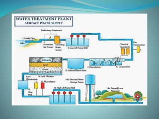
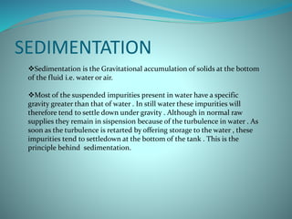
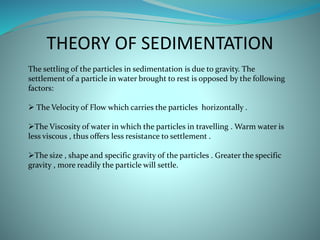
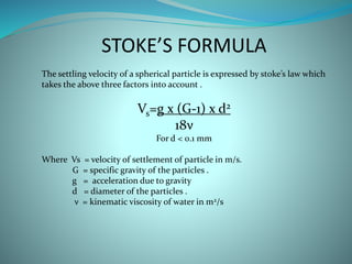
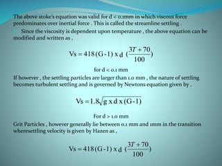
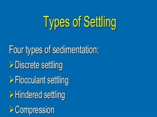
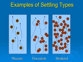
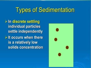
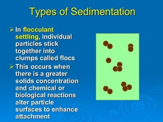
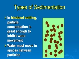
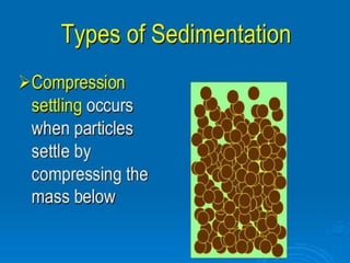
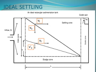
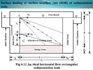
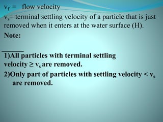
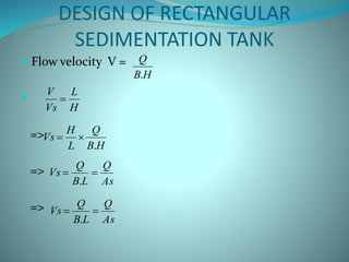
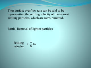
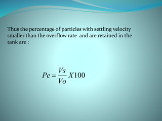
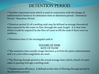
Group members:
Somu Kumar (BE/10523/14),
Nilkesh Mahato (BE/10538/14),
Manish Kumar (BE/10539/14),
Ashwini Kumar (BE/10544/14),
Nitin Agrawal (BE/10550/14),
Divya Pranay(BE/10564/14)
SEDIMENTATION
Sedimentation is the Gravitational accumulation of solids at the bottom
of the fluid i.e. water or air.
Most of the suspended impurities present in water have a specific
gravity greater than that of water . In still water these impurities will
therefore tend to settle down under gravity . Although in normal raw
supplies they remain in sispension because of the turbulence in water . As
soon as the turbulence is retarted by offering storage to the water , these
impurities tend to settledown at the bottom of the tank . This is the
principle behind sedimentation.
THEORY OF SEDIMENTATION
The settling of the particles in sedimentation is due to gravity. The
settlement of a particle in water brought to rest is opposed by the following
factors:
 The Velocity of Flow which carries the particles horizontally .
The Viscosity of water in which the particles in travelling . Warm water is
less viscous , thus offers less resistance to settlement .
The size , shape and specific gravity of the particles . Greater the specific
gravity , more readily the particle will settle.
STOKE’S FORMULA
The settling velocity of a spherical particle is expressed by stoke’s law which
takes the above three factors into account .
Vs=g x (G-1) x d2
18ν
For d < 0.1 mm
Where Vs = velocity of settlement of particle in m/s.
G = specific gravity of the particles .
g = acceleration due to gravity
d = diameter of the particles .
ν = kinematic viscosity of water in m2/s
The above stoke’s equation was valid for d < 0.1mm in which viscous force
predominates over inertial force . This is called the streamline settling .
 Since the viscosity is dependent upon temperature , the above equation can be
modified and written as ,
for d < 0.1 mm
If however , the settling particles are larger than 1.0 mm , the nature of settling
becomes turbulent settling and is governed by Newtons equation given by ,
For d > 1.0 mm
Grit Particles , however generally lie between 0.1 mm and 1mm in the transition
wheresettling velocity is given by Hazen as ,
)
100
703
(dx1)-(G418Vs


T
1)-(Gxdxg1.8Vs 
)
100
703
(dx1)-(G418Vs


T
SEDIMENTATION TANKS
Sedimentation Tanks are generally made up of reinforced concrete and may be
rectangular or circular in plan . The capacity and other dimension of the tank
should be properly designed so as to effect a fairly high percentage of removal of
suspended particles .
A plain sedimentation tank under normal conditions may remove as much as 70
% of the suspended impurities present in water . Long narrow rectangular tanks
with horizontal flow are generally preferred to the circular tanks with the
horizontal radial or spiral flow .
Storage reservoirs may also serve as sedimentation basins but they cannot effect
proper sedimentation because of factors such as density currents , the
turbulences caused by winds etc . and hence they cannot be relied upon .
Therefore , special basins are constructed to purify water by the process of
sedimentation .
1
TYPES OF SEDIMENTATION TANKS
1. Quiescent or fill and draw type:
Rectangular in plan.
Water is filled, allowed for retention period of 30 to 60 hrs (normally 24 hrs) then clear
water is drawn from outlet
Empty the tank and cleaning of sediment is done.
Needs more detention period, labours and supervision.
More than one tanks
Not used nowadays.
2
2. Continuous type:
A. Horizontal Flow Type
(a) Rectangular tanks with longitudinal flow
RECTANGULAR BASINS
 Rectangular basins are commonly found inlarge- scale water
treatment plants.
 Rectangular tanks are popular as they tend to have:
•High tolerance to shock overload
•Cost effectiveness due to lower
construction cost
•Redictable performance
• Lower maintenance
•Minimal short circuiting
(b) Circular Tank with radial flow, with central feed
CIRCULAR BASINS
Circular basins are often referred to as clarifiers.
These basins share some of the performance advantages of the
rectangular basins, but are generally more prone to short
circuiting and particle removal problems.
4
B. Vertical Flow Type
Working of a
Sedimentation Tank
SETTLING BASINS
 Overflow rates are used for design: Vo
settling surface area(m2
)
FlowRate(m3
/ s)
OverflowRate 
As long as vs is grater than vo the particles will
settle down for any depth of the sedimentation
tank.
ZONES IN SETTLING TANK
As = B x L Vol = B x L x H
B
As
Ac/s = B x H
Ac/s
IDEAL SETTLING
vf
vs
v’s
vf
5
Surface loading or surface overflow rate (SOR) of sedimentation
tank:
vf = flow velocity
vs= terminal settling velocity of a particle that is just
removed when it enters at the water surface (H).
Note:
1)All particles with terminal settling
velocity ≥ vs are removed.
2)Only part of particles with settling velocity < vs
are removed.
DESIGN OF RECTANGULAR
SEDIMENTATION TANK
 Flow velocity V =

=>
=>
=>
HB
Q
.
H
L
Vs
V

HB
Q
L
H
Vs
.

As
Q
LB
Q
Vs 
.
As
Q
LB
Q
Vs 
.
Thus surface overflow rate can be said to be
representing the settling velocity of the slowest
settling particles, which are 100% removed.
Partial Removal of lighter particles
Vo
H
h
Settling
velocity
100X
Vo
Vs
Pe 
Thus the percentage of particles with settling velocity
smaller than the overflow rate and are retained in the
tank are :
DETENTION PERIOD
Another important term which is used in connection with the design of
sedimentation basins is it’s detention time or detention period / Detention
Period / Retention Period .
Detetion period (t) of a settling tank may be defined as average theoretical
time required for the water to flow through the tank length . It is that time
which would be required by the flow of water to fill the tank if there were no
outflows .
Detention time (t) for rectangulat tank is
VOLUME OF TANK
RATE OF FLOW
The retention time usually ranges between 4 to 8 hrs for plain sedimentation
and 2 to 4 hrs when coagulants are used .
The flowing though period is the actual average time which a batch of water
takes in passing thorogh a settling tank .
Displacement efficiency is defined as the ratio of flowing through period to
the detention period .
CLEANING AND SLUDGE REMOVAL
The suspended materials contained by the raw supplies settle down at the
bottom of the sedimentation tank and have to be removed periodically . The
removal of deposited sludge and sediment is necessary not only because it
reduces the capacity of the tank and it’s detention period but also because it
leads to the formation and evolution of certain foul gasses due to the
decomposition of settled oragnic matter . Therefore the sedimentation tank
needs to be cleaned from time to time at frequent intervals either manually or
they are provided with mechanical arrangement for cleaning .
For tanks without mechanical sludge removal equipment , an additional
minimum depth of 0.8 – 1.2 m should be provided for storage of sediment and
this is called the sludge zone .
Sedimentation Tanks: Design and Working

Sedimentation Tanks: Design and Working

  • 1.
    Group members: Somu Kumar(BE/10523/14), Nilkesh Mahato (BE/10538/14), Manish Kumar (BE/10539/14), Ashwini Kumar (BE/10544/14), Nitin Agrawal (BE/10550/14), Divya Pranay(BE/10564/14)
  • 3.
    SEDIMENTATION Sedimentation is theGravitational accumulation of solids at the bottom of the fluid i.e. water or air. Most of the suspended impurities present in water have a specific gravity greater than that of water . In still water these impurities will therefore tend to settle down under gravity . Although in normal raw supplies they remain in sispension because of the turbulence in water . As soon as the turbulence is retarted by offering storage to the water , these impurities tend to settledown at the bottom of the tank . This is the principle behind sedimentation.
  • 4.
    THEORY OF SEDIMENTATION Thesettling of the particles in sedimentation is due to gravity. The settlement of a particle in water brought to rest is opposed by the following factors:  The Velocity of Flow which carries the particles horizontally . The Viscosity of water in which the particles in travelling . Warm water is less viscous , thus offers less resistance to settlement . The size , shape and specific gravity of the particles . Greater the specific gravity , more readily the particle will settle.
  • 5.
    STOKE’S FORMULA The settlingvelocity of a spherical particle is expressed by stoke’s law which takes the above three factors into account . Vs=g x (G-1) x d2 18ν For d < 0.1 mm Where Vs = velocity of settlement of particle in m/s. G = specific gravity of the particles . g = acceleration due to gravity d = diameter of the particles . ν = kinematic viscosity of water in m2/s
  • 6.
    The above stoke’sequation was valid for d < 0.1mm in which viscous force predominates over inertial force . This is called the streamline settling .  Since the viscosity is dependent upon temperature , the above equation can be modified and written as , for d < 0.1 mm If however , the settling particles are larger than 1.0 mm , the nature of settling becomes turbulent settling and is governed by Newtons equation given by , For d > 1.0 mm Grit Particles , however generally lie between 0.1 mm and 1mm in the transition wheresettling velocity is given by Hazen as , ) 100 703 (dx1)-(G418Vs   T 1)-(Gxdxg1.8Vs  ) 100 703 (dx1)-(G418Vs   T
  • 13.
    SEDIMENTATION TANKS Sedimentation Tanksare generally made up of reinforced concrete and may be rectangular or circular in plan . The capacity and other dimension of the tank should be properly designed so as to effect a fairly high percentage of removal of suspended particles . A plain sedimentation tank under normal conditions may remove as much as 70 % of the suspended impurities present in water . Long narrow rectangular tanks with horizontal flow are generally preferred to the circular tanks with the horizontal radial or spiral flow . Storage reservoirs may also serve as sedimentation basins but they cannot effect proper sedimentation because of factors such as density currents , the turbulences caused by winds etc . and hence they cannot be relied upon . Therefore , special basins are constructed to purify water by the process of sedimentation .
  • 14.
    1 TYPES OF SEDIMENTATIONTANKS 1. Quiescent or fill and draw type: Rectangular in plan. Water is filled, allowed for retention period of 30 to 60 hrs (normally 24 hrs) then clear water is drawn from outlet Empty the tank and cleaning of sediment is done. Needs more detention period, labours and supervision. More than one tanks Not used nowadays.
  • 16.
    2 2. Continuous type: A.Horizontal Flow Type (a) Rectangular tanks with longitudinal flow
  • 17.
    RECTANGULAR BASINS  Rectangularbasins are commonly found inlarge- scale water treatment plants.  Rectangular tanks are popular as they tend to have: •High tolerance to shock overload •Cost effectiveness due to lower construction cost •Redictable performance • Lower maintenance •Minimal short circuiting
  • 18.
    (b) Circular Tankwith radial flow, with central feed
  • 19.
    CIRCULAR BASINS Circular basinsare often referred to as clarifiers. These basins share some of the performance advantages of the rectangular basins, but are generally more prone to short circuiting and particle removal problems.
  • 20.
  • 21.
  • 22.
    SETTLING BASINS  Overflowrates are used for design: Vo settling surface area(m2 ) FlowRate(m3 / s) OverflowRate  As long as vs is grater than vo the particles will settle down for any depth of the sedimentation tank.
  • 23.
    ZONES IN SETTLINGTANK As = B x L Vol = B x L x H B As Ac/s = B x H Ac/s
  • 26.
  • 27.
    5 Surface loading orsurface overflow rate (SOR) of sedimentation tank:
  • 28.
    vf = flowvelocity vs= terminal settling velocity of a particle that is just removed when it enters at the water surface (H). Note: 1)All particles with terminal settling velocity ≥ vs are removed. 2)Only part of particles with settling velocity < vs are removed.
  • 29.
    DESIGN OF RECTANGULAR SEDIMENTATIONTANK  Flow velocity V =  => => => HB Q . H L Vs V  HB Q L H Vs .  As Q LB Q Vs  . As Q LB Q Vs  .
  • 30.
    Thus surface overflowrate can be said to be representing the settling velocity of the slowest settling particles, which are 100% removed. Partial Removal of lighter particles Vo H h Settling velocity
  • 31.
    100X Vo Vs Pe  Thus thepercentage of particles with settling velocity smaller than the overflow rate and are retained in the tank are :
  • 32.
    DETENTION PERIOD Another importantterm which is used in connection with the design of sedimentation basins is it’s detention time or detention period / Detention Period / Retention Period . Detetion period (t) of a settling tank may be defined as average theoretical time required for the water to flow through the tank length . It is that time which would be required by the flow of water to fill the tank if there were no outflows . Detention time (t) for rectangulat tank is VOLUME OF TANK RATE OF FLOW The retention time usually ranges between 4 to 8 hrs for plain sedimentation and 2 to 4 hrs when coagulants are used . The flowing though period is the actual average time which a batch of water takes in passing thorogh a settling tank . Displacement efficiency is defined as the ratio of flowing through period to the detention period .
  • 36.
    CLEANING AND SLUDGEREMOVAL The suspended materials contained by the raw supplies settle down at the bottom of the sedimentation tank and have to be removed periodically . The removal of deposited sludge and sediment is necessary not only because it reduces the capacity of the tank and it’s detention period but also because it leads to the formation and evolution of certain foul gasses due to the decomposition of settled oragnic matter . Therefore the sedimentation tank needs to be cleaned from time to time at frequent intervals either manually or they are provided with mechanical arrangement for cleaning . For tanks without mechanical sludge removal equipment , an additional minimum depth of 0.8 – 1.2 m should be provided for storage of sediment and this is called the sludge zone .