PART PROGRAM
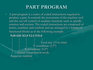
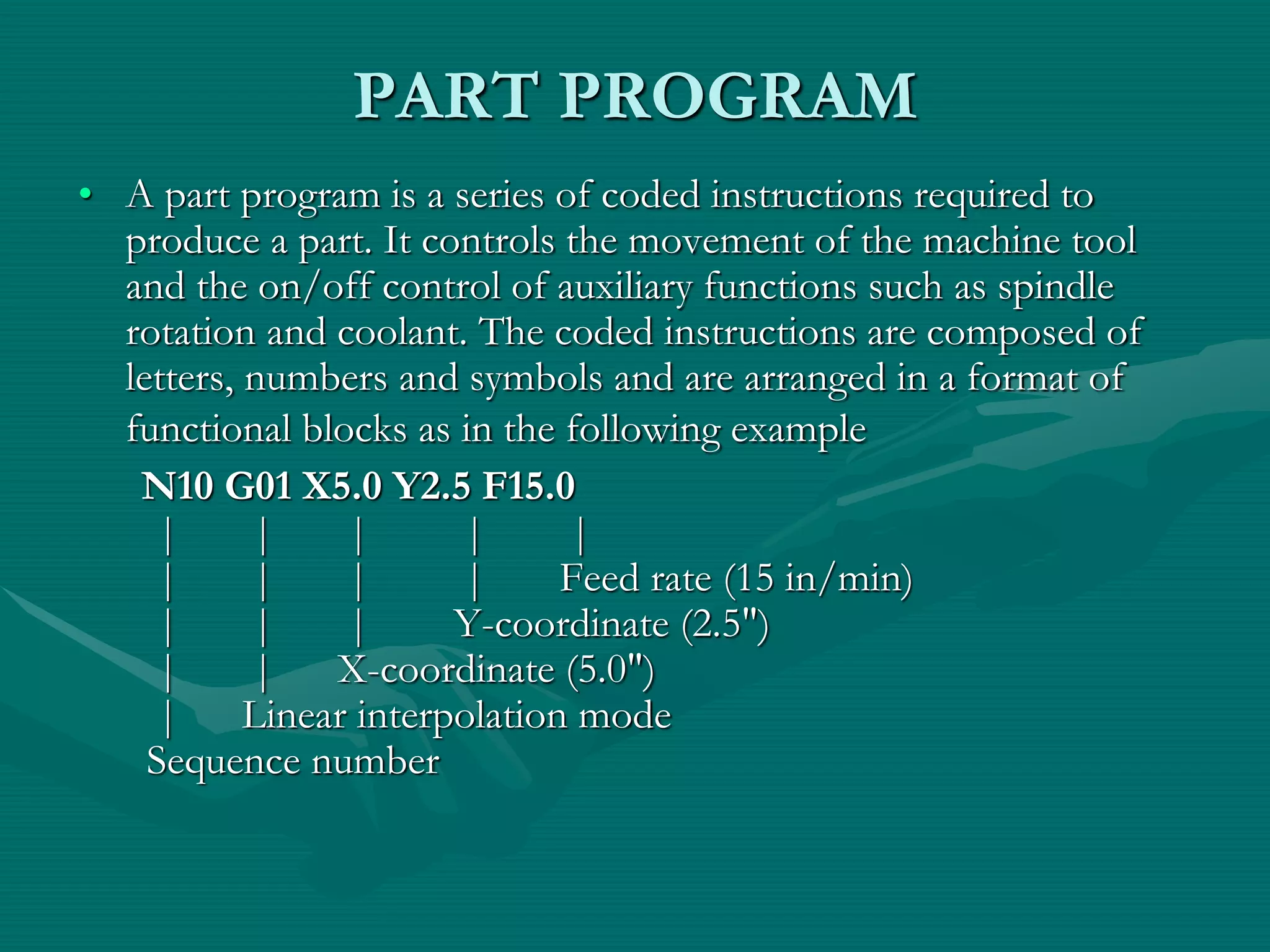
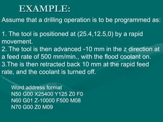
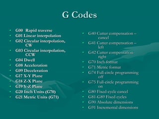
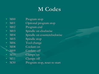
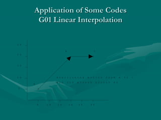
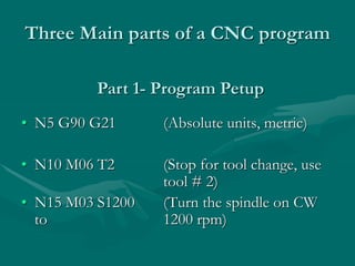
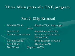
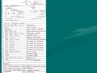
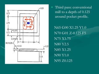
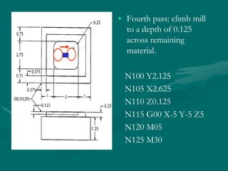
• A part program is a series of coded instructions required to
produce a part. It controls the movement of the machine tool
and the on/off control of auxiliary functions such as spindle
rotation and coolant. The coded instructions are composed of
letters, numbers and symbols and are arranged in a format of
functional blocks as in the following example
N10 G01 X5.0 Y2.5 F15.0
| | | | |
| | | | Feed rate (15 in/min)
| | | Y-coordinate (2.5")
| | X-coordinate (5.0")
| Linear interpolation mode
Sequence number
EXAMPLE:
Assume that a drilling operation is to be programmed as:
1. The tool is positioned at (25.4,12.5,0) by a rapid
movement.
2. The tool is then advanced -10 mm in the z direction at
a feed rate of 500 mm/min., with the flood coolant on.
3.The is then retracted back 10 mm at the rapid feed
rate, and the coolant is turned off.
Word address format
N50 G00 X25400 Y125 Z0 F0
N60 G01 Z-10000 F500 M08
N70 G00 Z0 M09
G Codes
• G00 Rapid traverse
• G01 Linear interpolation
• G02 Circular interpolation,
CW
• G03 Circular interpolation,
CCW
• G04 Dwell
• G08 Acceleration
• G09 Deceleration
• G17 X-Y Plane
• G18 Z-X Plane
• G19 Y-Z Plane
• G20 Inch Units (G70)
• G21 Metric Units (G71)
• G40 Cutter compensation –
cancel
• G41 Cutter compensation –
left
• G42 Cutter compensation-
right
• G70 Inch format
• G71 Metric format
• G74 Full-circle programming
off
• G75 Full-circle programming
on
• G80 Fixed-cycle cancel
• G81-G89 Fixed cycles
• G90 Absolute dimensions
• G91 Incremental dimensions
M Codes
• M00 Program stop
• M01 Optional program stop
• M02 Program end
• M03 Spindle on clockwise
• M04 Spindle on counterclockwise
• M05 Spindle stop
• M06 Tool change
• M08 Coolant on
• M09 Coolant off
• M10 Clamps on
• M11 Clamps off
• M30 Program stop, reset to start
Application of Some Codes
G01 Linear Interpolation
5
1 0
1 5
2 0
2 5
5 1 0 1 5 2 0 2 5 3 0
A
B C
P o s i t i o n i n g m o t i o n f r o m A t o C
N 1 0 G 0 0 X 3 0 0 0 0 Y 2 0 0 0 0 F 0
N10 G00 X1 Z1
N15 Z0.1
N20 G01 Z-0.125 F5
N25 X2 Z2 F10
G01 Linear Interpolation
X
Z
Three Main parts of a CNC program
• N5 G90 G21 (Absolute units, metric)
• N10 M06 T2 (Stop for tool change, use
tool # 2)
• N15 M03 S1200 (Turn the spindle on CW
to 1200 rpm)
Part 1- Program Petup
Three Main parts of a CNC program
• N20 G00 X1 Y1 (Rapid to X1,Y1 from origin
point)
• N25 Z0.125 (Rapid down to Z0.125)
• N30 G01 Z-0.125 F100 (Feed down to Z-0.125 at
100 mm/min)
• N35 G01 X2 Y2 (Feed diagonally to X2,Y2)
• N40 G00 Z1 (Rapid up to Z1)
• N45 X0 Y0 (Rapid to X0,Y0)
Part 2- Chip Removal
Three Main parts of a CNC program
• N50 M05 (Turn the spindle off)
• N55 M00 (Program stop)
Part 3- System Shutdown
EXAMPLE OPERATION on CNC
MILLING MACHINE
G-CODE PROGRAM
• First pass : conventional mill to a
depth of 0.125 around edge profile.
Tool 1 is a ½ inch dia. end mill.
%
:1002
N5 G90 G20
N10 M06 T1
N15 M03 S1200
N20 G00 X0.125 Y0.125
N30 Z0.125
N35 G01 Z-0.125 F5
N40 X3.875
N45 Y4.125
N50 X0.125
N55 Y0.125
• Second pass:
conventional mill to a
depth of 0.25 around
edge profile.
N35 Z-0.250
N40 X3.875
N45 Y4.125
N50 X0.125
N55 Y0.125
N60 Z0.125
• Third pass: conventional
mill to a depth of 0.125
around pocket profile.
N65 G00 X1.25 Y1.0
N70 G01 Z-0.125 F5
N75 X1.75
N80 Y2.5
N85 X1.25
N90 Y1.0
N95 Z0.125
• Fourth pass: climb mill
to a depth of 0.125
across remaining
material.
N100 Y2.125
N105 X2.625
N110 Z0.125
N115 G00 X-5 Y-5 Z5
N120 M05
N125 M30
CIMS Lab.ppt

CIMS Lab.ppt

  • 1.
    PART PROGRAM • Apart program is a series of coded instructions required to produce a part. It controls the movement of the machine tool and the on/off control of auxiliary functions such as spindle rotation and coolant. The coded instructions are composed of letters, numbers and symbols and are arranged in a format of functional blocks as in the following example N10 G01 X5.0 Y2.5 F15.0 | | | | | | | | | Feed rate (15 in/min) | | | Y-coordinate (2.5") | | X-coordinate (5.0") | Linear interpolation mode Sequence number
  • 2.
    EXAMPLE: Assume that adrilling operation is to be programmed as: 1. The tool is positioned at (25.4,12.5,0) by a rapid movement. 2. The tool is then advanced -10 mm in the z direction at a feed rate of 500 mm/min., with the flood coolant on. 3.The is then retracted back 10 mm at the rapid feed rate, and the coolant is turned off. Word address format N50 G00 X25400 Y125 Z0 F0 N60 G01 Z-10000 F500 M08 N70 G00 Z0 M09
  • 3.
    G Codes • G00Rapid traverse • G01 Linear interpolation • G02 Circular interpolation, CW • G03 Circular interpolation, CCW • G04 Dwell • G08 Acceleration • G09 Deceleration • G17 X-Y Plane • G18 Z-X Plane • G19 Y-Z Plane • G20 Inch Units (G70) • G21 Metric Units (G71) • G40 Cutter compensation – cancel • G41 Cutter compensation – left • G42 Cutter compensation- right • G70 Inch format • G71 Metric format • G74 Full-circle programming off • G75 Full-circle programming on • G80 Fixed-cycle cancel • G81-G89 Fixed cycles • G90 Absolute dimensions • G91 Incremental dimensions
  • 4.
    M Codes • M00Program stop • M01 Optional program stop • M02 Program end • M03 Spindle on clockwise • M04 Spindle on counterclockwise • M05 Spindle stop • M06 Tool change • M08 Coolant on • M09 Coolant off • M10 Clamps on • M11 Clamps off • M30 Program stop, reset to start
  • 5.
    Application of SomeCodes G01 Linear Interpolation 5 1 0 1 5 2 0 2 5 5 1 0 1 5 2 0 2 5 3 0 A B C P o s i t i o n i n g m o t i o n f r o m A t o C N 1 0 G 0 0 X 3 0 0 0 0 Y 2 0 0 0 0 F 0
  • 6.
    N10 G00 X1Z1 N15 Z0.1 N20 G01 Z-0.125 F5 N25 X2 Z2 F10 G01 Linear Interpolation X Z
  • 7.
    Three Main partsof a CNC program • N5 G90 G21 (Absolute units, metric) • N10 M06 T2 (Stop for tool change, use tool # 2) • N15 M03 S1200 (Turn the spindle on CW to 1200 rpm) Part 1- Program Petup
  • 8.
    Three Main partsof a CNC program • N20 G00 X1 Y1 (Rapid to X1,Y1 from origin point) • N25 Z0.125 (Rapid down to Z0.125) • N30 G01 Z-0.125 F100 (Feed down to Z-0.125 at 100 mm/min) • N35 G01 X2 Y2 (Feed diagonally to X2,Y2) • N40 G00 Z1 (Rapid up to Z1) • N45 X0 Y0 (Rapid to X0,Y0) Part 2- Chip Removal
  • 9.
    Three Main partsof a CNC program • N50 M05 (Turn the spindle off) • N55 M00 (Program stop) Part 3- System Shutdown
  • 12.
    EXAMPLE OPERATION onCNC MILLING MACHINE
  • 13.
    G-CODE PROGRAM • Firstpass : conventional mill to a depth of 0.125 around edge profile. Tool 1 is a ½ inch dia. end mill. % :1002 N5 G90 G20 N10 M06 T1 N15 M03 S1200 N20 G00 X0.125 Y0.125 N30 Z0.125 N35 G01 Z-0.125 F5 N40 X3.875 N45 Y4.125 N50 X0.125 N55 Y0.125
  • 14.
    • Second pass: conventionalmill to a depth of 0.25 around edge profile. N35 Z-0.250 N40 X3.875 N45 Y4.125 N50 X0.125 N55 Y0.125 N60 Z0.125
  • 15.
    • Third pass:conventional mill to a depth of 0.125 around pocket profile. N65 G00 X1.25 Y1.0 N70 G01 Z-0.125 F5 N75 X1.75 N80 Y2.5 N85 X1.25 N90 Y1.0 N95 Z0.125
  • 16.
    • Fourth pass:climb mill to a depth of 0.125 across remaining material. N100 Y2.125 N105 X2.625 N110 Z0.125 N115 G00 X-5 Y-5 Z5 N120 M05 N125 M30