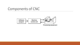
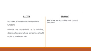
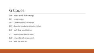
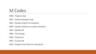
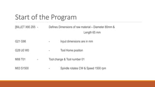
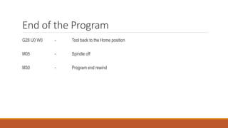
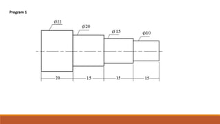
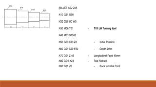
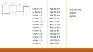
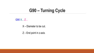
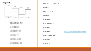
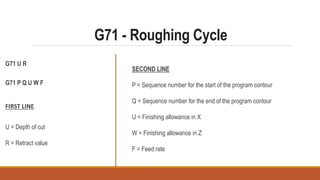
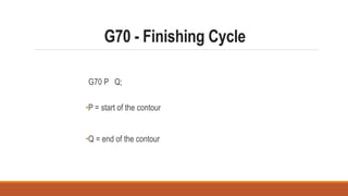
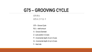
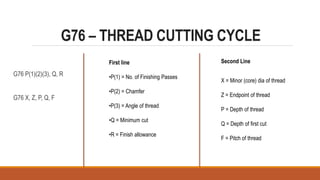
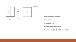
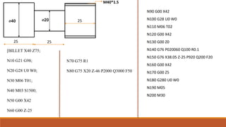
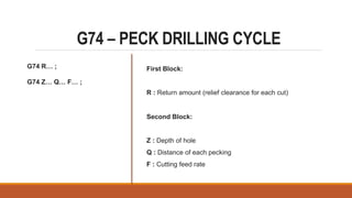
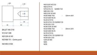
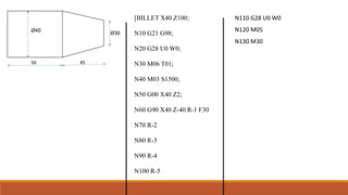
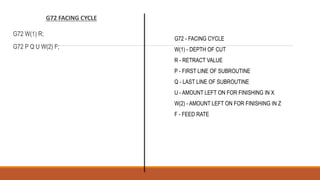
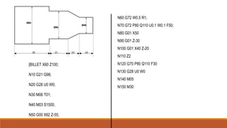
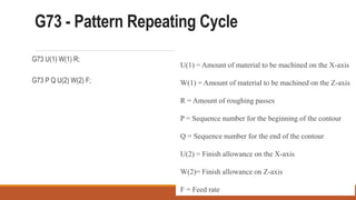
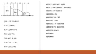
CNC PROGRAMMING
Components of CNC
Part Programming
CNC part programming involves a series of alpha-numeric coded instructions that are
required to produce a part.
The program controls the machine tool movements and controls auxiliary functions
auxiliary functions including spindle, coolant, and rotation.
G - CODE
G-Codes are about Geometry control
functions
controls the movements of a machine,
dictating how and where a machine should
move to produce a part
M - CODE
M-Codes are about Machine control
functions
G Codes
G00 - Rapid move (not cutting)
G01 - Linear move
G02 - Clockwise circular motion
G03 – Counter clockwise circular motion
G20 - inch data specification
G21 - metric data specification
G28 - return to reference point
G98 - feed per minute
M Codes
M00 – Program stop
M01 – Optional program stop
M03 – Spindle rotation on clockwise
M04 – Spindle rotation on counter clockwise
M05 – Spindle off
M06 – Tool change
M08 – Coolant on
M09 – Coolant off
M30 – Program end, Return to start point
Start of the Program
[BILLET X80 Z65 - Defines Dimensions of raw material – Diameter 80mm &
Length 65 mm
G21 G98 - Input dimensions are in mm
G28 U0 W0 - Tool Home position
M06 T01 - Tool change & Tool number 01
M03 S1500 - Spindle rotates CW & Speed 1500 rpm
End of the Program
G28 U0 W0 - Tool back to the Home position
M05 - Spindle off
M30 - Program end rewind
Program 1
[BILLET X22 Z65
N10 G21 G98
N20 G28 U0 W0
N30 M06 T01 - T01 LH Turning tool
N40 M03 S1500
N50 G00 X23 Z2 - Initial Position
N60 G01 X20 F50 - Depth 2mm
N70 G01 Z-45 - Longitudinal Feed 45mm
N80 GO1 X23 - Tool Retract
N90 G01 Z0 - Back to Initial Point
N100 G01 X18
N110 G01 Z-30
N120 G01 X19
N130 G01 Z0
N140 G01 X16
N150 G01 Z-30
N160 G01 X17
N170 G01 Z0
N180 G01 X15
N190 G01 Z-30
N200 G01 X16
N210 G01 Z0
N220 G01 X13
N230 G01 Z-15
N240 G01 X14
N250 G01 Z0
N260 G01 X11
N270 G01 Z-15
N280 G01 X12
N290 G01 Z0
N300 G01 X10
N310 G01 Z-15
N320 GO1 X11
N330 GO1 Z5
N340 G28 U0 W0
N350 M05
N360 M30
G90 – Turning Cycle
G90 X... Z...
X – Diameter to be cut.
Z – End point in z-axis.
N60 G90 X21 Z-45 F30
N70 X20
N 80 X18 Z-30
N90 X16
N100 X15
N110 X13 Z-15
N120 X11
N130 X10
N140 G28 U0 W0
N150 M05
N160 M30
https://youtu.be/Uom3kaqQ0Lo
[BILLET X22 Z65
N10 G21 G98
N20 G28 U0 W0
N30 M06 T01
N40 M03 S1500
N50 G00 X23 Z2
Program 2
G71 - Roughing Cycle
G71 U R
G71 P Q U W F
FIRST LINE
U = Depth of cut
R = Retract value
SECOND LINE
P = Sequence number for the start of the program contour
Q = Sequence number for the end of the program contour
U = Finishing allowance in X
W = Finishing allowance in Z
F = Feed rate
G70 - Finishing Cycle
G70 P Q;
•P = start of the contour
•Q = end of the contour
PROGRAM 3
[BILLET X22 Z60;
N10 G21 G98;
N20 G28 U0 W0;
N30 M06 T01;
N40 M03 S1500;
N50 G00 X22 Z2;
N60 G01 X0
N70 G71 U0.5 R1
N80 G71 P90 Q150 U0.1 W0.1 F50
N90 G01 Z0
N100 G03 X10 Z-5 R5
N110 G01 Z-17
N120 G01 X14 Z-25
N130 G01 Z-30
N140 G02 X19 Z-35 R5
N150 G01 Z-37
N160 G70 P90 Q150 F20
N170 G28 U0 W0
N180 M05
N190 M30
G75 – GROOVING CYCLE
G75 R(1)
G75 X Z P Q F
G75 – Groove Cycle
R(1) – relief amount
X – Groove Diameter
Z - Last position in Z-axis
P – Incremental depth of cut in X-axis
Q – Incremental depth of cut in Z-axis
F – feed rate
PROGRAM 4
N50 G00 X82
N55 G00 Z-20;
N60 G75 R1
N70 G75 X50 Z-31 P2000 Q3000 F50
N80 G00 X82
N90 G28 U0 W0
N100 M05
N110 M30
[BILLET X80 Z65;
N10 G21 G98;
N20 G28 U0 W0;
N30 M06 T01;
N40 M03 S1500;
G76 – THREAD CUTTING CYCLE
G76 P(1)(2)(3), Q, R
G76 X, Z, P, Q, F
First line
•P(1) = No. of Finishing Passes
•P(2) = Chamfer
•P(3) = Angle of thread
•Q = Minimum cut
•R = Finish allowance
Second Line
X = Minor (core) dia of thread
Z = Endpoint of thread
P = Depth of thread
Q = Depth of first cut
F = Pitch of thread
Major Diameter (D) = 40 mm
Pitch = 1.5 mm
Thread angle = 60⁰
Thread Height = 0.6134*pitch
Minor Diameter (d) = D – (2*Thread Height)
N70 G75 R1
N80 G75 X20 Z-46 P2000 Q3000 F50
N90 G00 X42
N100 G28 U0 W0
N110 M06 T02
N120 G00 X42
N130 G00 Z0
N140 G76 P020060 Q100 R0.1
N150 G76 X38.05 Z-25 P920 Q200 F20
N160 G00 X42
N170 G00 Z5
N180 G280 U0 W0
N190 M05
N200 M30
⌀40 ⌀20
M40*1.5
25 25
25
[BILLET X40 Z75;
N10 G21 G98;
N20 G28 U0 W0;
N30 M06 T01;
N40 M03 S1500;
N50 G00 X42
N60 G00 Z-25
G74 – PECK DRILLING CYCLE
G74 R… ;
G74 Z… Q… F… ;
First Block:
R : Return amount (relief clearance for each cut)
Second Block:
Z : Depth of hole
Q : Distance of each pecking
F : Cutting feed rate
[BILLET X60 Z100
N10 G21 G98
N20 G28 U0 W0
N30 M06 T01 – Centre punch
N40 M03 S1500
N50 GOO X0 Z10
N60 G74 R1
N70 G74 Z-5 Q2000 F10
N80 G01 Z10
N90 G28 U0 W0
N100 M06 T02 - 10mm drill
N110 G00 X0 Z5
N120 G74 R1
N120 G74 Z-35 Q2000 F10
N130 G01 Z10
N140 G28 U0 W0
N150 M06 T03 - 20mm drill
N160 G00 X0 Z5
N170 G74 R1
N180 G74 Z-35 Q2000 F10
N190 G01 Z10
G28 U0 W0
M05
M30
CNC MILLING
PROGRAMMING
https://gcodetutor.com/cnc-machine-training/cnc-lathe-programming.html
[BILLET X40 Z100;
N10 G21 G98;
N20 G28 U0 W0;
N30 M06 T01;
N40 M03 S1500;
N50 G00 X40 Z2;
N60 G90 X40 Z-40 R-1 F30
N70 R-2
N80 R-3
N90 R-4
N100 R-5
N110 G28 U0 W0
N120 M05
N130 M30
G72 FACING CYCLE
G72 W(1) R;
G72 P Q U W(2) F;
G72 - FACING CYCLE
W(1) - DEPTH OF CUT
R - RETRACT VALUE
P - FIRST LINE OF SUBROUTINE
Q - LAST LINE OF SUBROUTINE
U - AMOUNT LEFT ON FOR FINISHING IN X
W(2) - AMOUNT LEFT ON FOR FINISHING IN Z
F - FEED RATE
[BILLET X60 Z100;
N10 G21 G98;
N20 G28 U0 W0;
N30 M06 T01;
N40 M03 S1500;
N50 G00 X62 Z-55;
N60 G72 W0.5 R1;
N70 G72 P80 Q110 U0.1 W0.1 F50;
N80 G01 X50
N90 G01 Z-30
N100 G01 X40 Z-20
N110 Z2
N120 G70 P80 Q110 F30
N130 G28 U0 W0
N140 M05
N150 M30
G73 - Pattern Repeating Cycle
G73 U(1) W(1) R;
G73 P Q U(2) W(2) F;
U(1) = Amount of material to be machined on the X-axis
W(1) = Amount of material to be machined on the Z-axis
R = Amount of roughing passes
P = Sequence number for the beginning of the contour
Q = Sequence number for the end of the contour
U(2) = Finish allowance on the X-axis
W(2)= Finish allowance on Z-axis
F = Feed rate
[BILLET X70 Z160;
N10 G21 G98;
N20 G28 U0 W0;
N30 M06 T01;
N40 M03 S1500;
N50 G00 X72 Z2;
N60 G01 X0 Z0
N70 G73 U0.5 W0.5 R0.25
N80 G73 P90 Q130 U0.1 W0.1 F50
N90 G03 X20 Z-20 R10
N100 G01 Z-45
N110 G01 X40 Z-80
N120 G01 Z-105
N130 G02 X70 Z-120 R15
N140 G70 P90 Q130 F20
N150 G28 U0 W0
N160 M05
N170 M30

CNC Programming.pptx

  • 1.
  • 2.
  • 3.
    Part Programming CNC partprogramming involves a series of alpha-numeric coded instructions that are required to produce a part. The program controls the machine tool movements and controls auxiliary functions auxiliary functions including spindle, coolant, and rotation.
  • 4.
    G - CODE G-Codesare about Geometry control functions controls the movements of a machine, dictating how and where a machine should move to produce a part M - CODE M-Codes are about Machine control functions
  • 5.
    G Codes G00 -Rapid move (not cutting) G01 - Linear move G02 - Clockwise circular motion G03 – Counter clockwise circular motion G20 - inch data specification G21 - metric data specification G28 - return to reference point G98 - feed per minute
  • 6.
    M Codes M00 –Program stop M01 – Optional program stop M03 – Spindle rotation on clockwise M04 – Spindle rotation on counter clockwise M05 – Spindle off M06 – Tool change M08 – Coolant on M09 – Coolant off M30 – Program end, Return to start point
  • 7.
    Start of theProgram [BILLET X80 Z65 - Defines Dimensions of raw material – Diameter 80mm & Length 65 mm G21 G98 - Input dimensions are in mm G28 U0 W0 - Tool Home position M06 T01 - Tool change & Tool number 01 M03 S1500 - Spindle rotates CW & Speed 1500 rpm
  • 8.
    End of theProgram G28 U0 W0 - Tool back to the Home position M05 - Spindle off M30 - Program end rewind
  • 9.
  • 10.
    [BILLET X22 Z65 N10G21 G98 N20 G28 U0 W0 N30 M06 T01 - T01 LH Turning tool N40 M03 S1500 N50 G00 X23 Z2 - Initial Position N60 G01 X20 F50 - Depth 2mm N70 G01 Z-45 - Longitudinal Feed 45mm N80 GO1 X23 - Tool Retract N90 G01 Z0 - Back to Initial Point
  • 11.
    N100 G01 X18 N110G01 Z-30 N120 G01 X19 N130 G01 Z0 N140 G01 X16 N150 G01 Z-30 N160 G01 X17 N170 G01 Z0 N180 G01 X15 N190 G01 Z-30 N200 G01 X16 N210 G01 Z0 N220 G01 X13 N230 G01 Z-15 N240 G01 X14 N250 G01 Z0 N260 G01 X11 N270 G01 Z-15 N280 G01 X12 N290 G01 Z0 N300 G01 X10 N310 G01 Z-15 N320 GO1 X11 N330 GO1 Z5 N340 G28 U0 W0 N350 M05 N360 M30
  • 12.
    G90 – TurningCycle G90 X... Z... X – Diameter to be cut. Z – End point in z-axis.
  • 13.
    N60 G90 X21Z-45 F30 N70 X20 N 80 X18 Z-30 N90 X16 N100 X15 N110 X13 Z-15 N120 X11 N130 X10 N140 G28 U0 W0 N150 M05 N160 M30 https://youtu.be/Uom3kaqQ0Lo [BILLET X22 Z65 N10 G21 G98 N20 G28 U0 W0 N30 M06 T01 N40 M03 S1500 N50 G00 X23 Z2 Program 2
  • 14.
    G71 - RoughingCycle G71 U R G71 P Q U W F FIRST LINE U = Depth of cut R = Retract value SECOND LINE P = Sequence number for the start of the program contour Q = Sequence number for the end of the program contour U = Finishing allowance in X W = Finishing allowance in Z F = Feed rate
  • 15.
    G70 - FinishingCycle G70 P Q; •P = start of the contour •Q = end of the contour
  • 16.
  • 17.
    [BILLET X22 Z60; N10G21 G98; N20 G28 U0 W0; N30 M06 T01; N40 M03 S1500; N50 G00 X22 Z2; N60 G01 X0 N70 G71 U0.5 R1 N80 G71 P90 Q150 U0.1 W0.1 F50 N90 G01 Z0 N100 G03 X10 Z-5 R5 N110 G01 Z-17 N120 G01 X14 Z-25 N130 G01 Z-30 N140 G02 X19 Z-35 R5 N150 G01 Z-37 N160 G70 P90 Q150 F20 N170 G28 U0 W0 N180 M05 N190 M30
  • 18.
    G75 – GROOVINGCYCLE G75 R(1) G75 X Z P Q F G75 – Groove Cycle R(1) – relief amount X – Groove Diameter Z - Last position in Z-axis P – Incremental depth of cut in X-axis Q – Incremental depth of cut in Z-axis F – feed rate
  • 19.
  • 20.
    N50 G00 X82 N55G00 Z-20; N60 G75 R1 N70 G75 X50 Z-31 P2000 Q3000 F50 N80 G00 X82 N90 G28 U0 W0 N100 M05 N110 M30 [BILLET X80 Z65; N10 G21 G98; N20 G28 U0 W0; N30 M06 T01; N40 M03 S1500;
  • 21.
    G76 – THREADCUTTING CYCLE G76 P(1)(2)(3), Q, R G76 X, Z, P, Q, F First line •P(1) = No. of Finishing Passes •P(2) = Chamfer •P(3) = Angle of thread •Q = Minimum cut •R = Finish allowance Second Line X = Minor (core) dia of thread Z = Endpoint of thread P = Depth of thread Q = Depth of first cut F = Pitch of thread
  • 22.
    Major Diameter (D)= 40 mm Pitch = 1.5 mm Thread angle = 60⁰ Thread Height = 0.6134*pitch Minor Diameter (d) = D – (2*Thread Height)
  • 23.
    N70 G75 R1 N80G75 X20 Z-46 P2000 Q3000 F50 N90 G00 X42 N100 G28 U0 W0 N110 M06 T02 N120 G00 X42 N130 G00 Z0 N140 G76 P020060 Q100 R0.1 N150 G76 X38.05 Z-25 P920 Q200 F20 N160 G00 X42 N170 G00 Z5 N180 G280 U0 W0 N190 M05 N200 M30 ⌀40 ⌀20 M40*1.5 25 25 25 [BILLET X40 Z75; N10 G21 G98; N20 G28 U0 W0; N30 M06 T01; N40 M03 S1500; N50 G00 X42 N60 G00 Z-25
  • 24.
    G74 – PECKDRILLING CYCLE G74 R… ; G74 Z… Q… F… ; First Block: R : Return amount (relief clearance for each cut) Second Block: Z : Depth of hole Q : Distance of each pecking F : Cutting feed rate
  • 26.
    [BILLET X60 Z100 N10G21 G98 N20 G28 U0 W0 N30 M06 T01 – Centre punch N40 M03 S1500 N50 GOO X0 Z10 N60 G74 R1 N70 G74 Z-5 Q2000 F10 N80 G01 Z10 N90 G28 U0 W0 N100 M06 T02 - 10mm drill N110 G00 X0 Z5 N120 G74 R1 N120 G74 Z-35 Q2000 F10 N130 G01 Z10 N140 G28 U0 W0 N150 M06 T03 - 20mm drill N160 G00 X0 Z5 N170 G74 R1 N180 G74 Z-35 Q2000 F10 N190 G01 Z10 G28 U0 W0 M05 M30
  • 30.
  • 31.
  • 32.
    [BILLET X40 Z100; N10G21 G98; N20 G28 U0 W0; N30 M06 T01; N40 M03 S1500; N50 G00 X40 Z2; N60 G90 X40 Z-40 R-1 F30 N70 R-2 N80 R-3 N90 R-4 N100 R-5 N110 G28 U0 W0 N120 M05 N130 M30
  • 33.
    G72 FACING CYCLE G72W(1) R; G72 P Q U W(2) F; G72 - FACING CYCLE W(1) - DEPTH OF CUT R - RETRACT VALUE P - FIRST LINE OF SUBROUTINE Q - LAST LINE OF SUBROUTINE U - AMOUNT LEFT ON FOR FINISHING IN X W(2) - AMOUNT LEFT ON FOR FINISHING IN Z F - FEED RATE
  • 34.
    [BILLET X60 Z100; N10G21 G98; N20 G28 U0 W0; N30 M06 T01; N40 M03 S1500; N50 G00 X62 Z-55; N60 G72 W0.5 R1; N70 G72 P80 Q110 U0.1 W0.1 F50; N80 G01 X50 N90 G01 Z-30 N100 G01 X40 Z-20 N110 Z2 N120 G70 P80 Q110 F30 N130 G28 U0 W0 N140 M05 N150 M30
  • 35.
    G73 - PatternRepeating Cycle G73 U(1) W(1) R; G73 P Q U(2) W(2) F; U(1) = Amount of material to be machined on the X-axis W(1) = Amount of material to be machined on the Z-axis R = Amount of roughing passes P = Sequence number for the beginning of the contour Q = Sequence number for the end of the contour U(2) = Finish allowance on the X-axis W(2)= Finish allowance on Z-axis F = Feed rate
  • 36.
    [BILLET X70 Z160; N10G21 G98; N20 G28 U0 W0; N30 M06 T01; N40 M03 S1500; N50 G00 X72 Z2; N60 G01 X0 Z0 N70 G73 U0.5 W0.5 R0.25 N80 G73 P90 Q130 U0.1 W0.1 F50 N90 G03 X20 Z-20 R10 N100 G01 Z-45 N110 G01 X40 Z-80 N120 G01 Z-105 N130 G02 X70 Z-120 R15 N140 G70 P90 Q130 F20 N150 G28 U0 W0 N160 M05 N170 M30