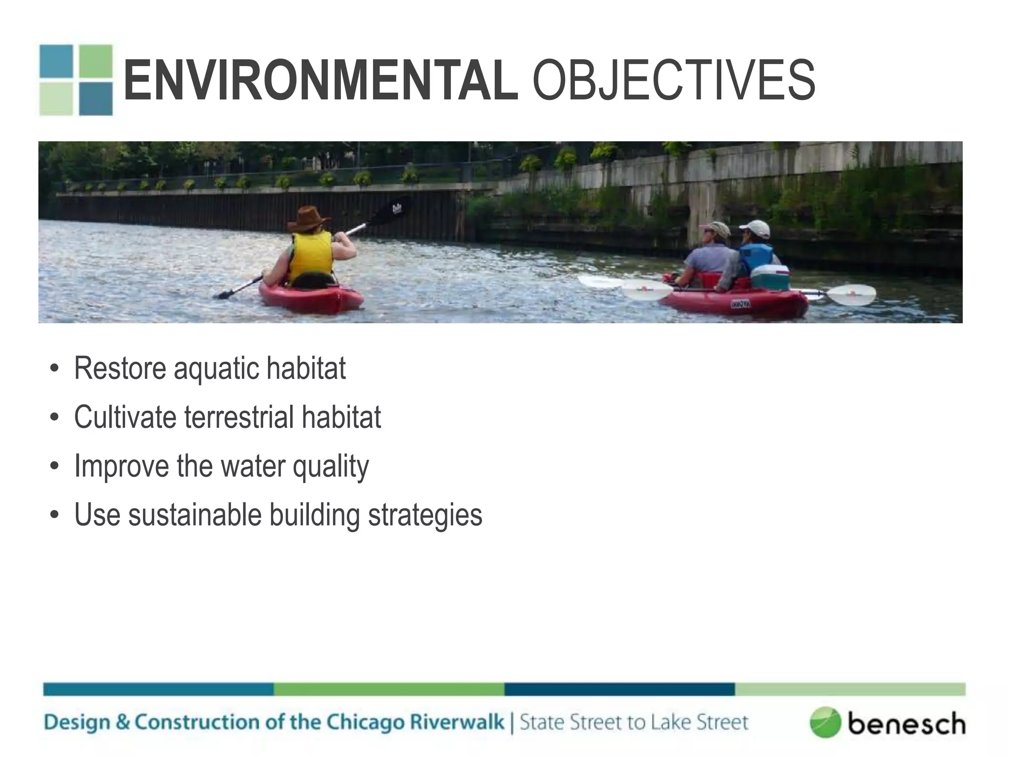
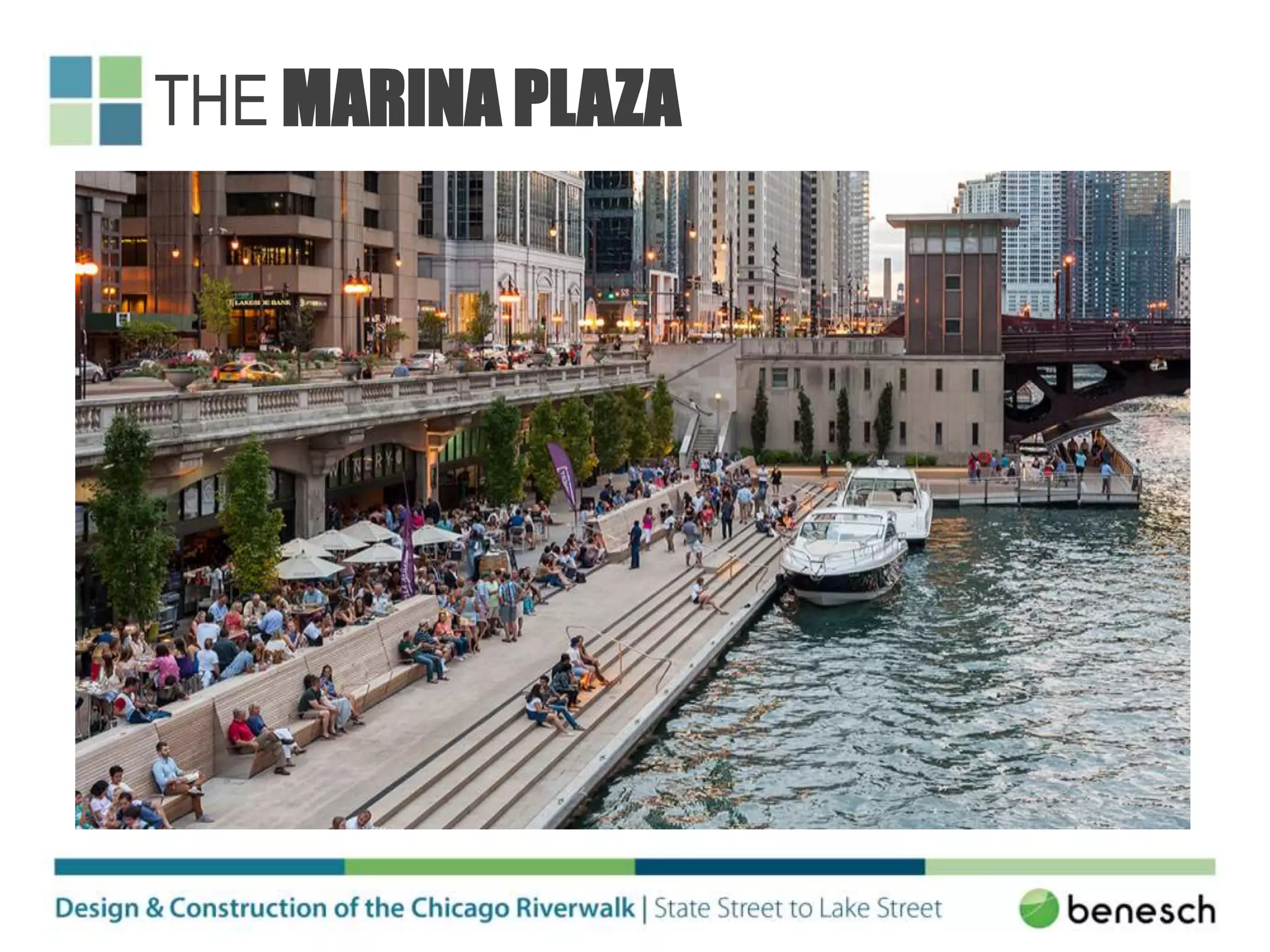
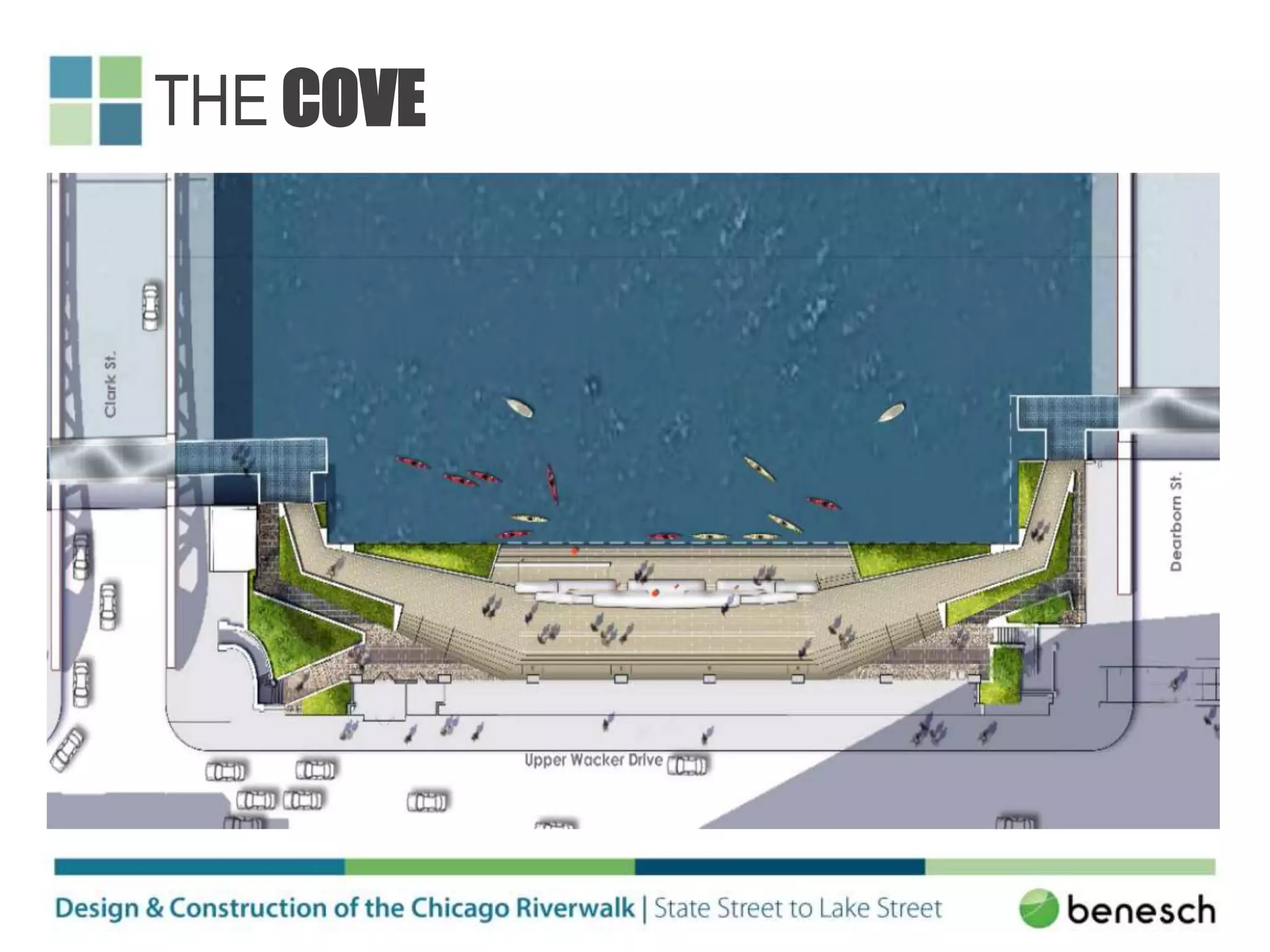
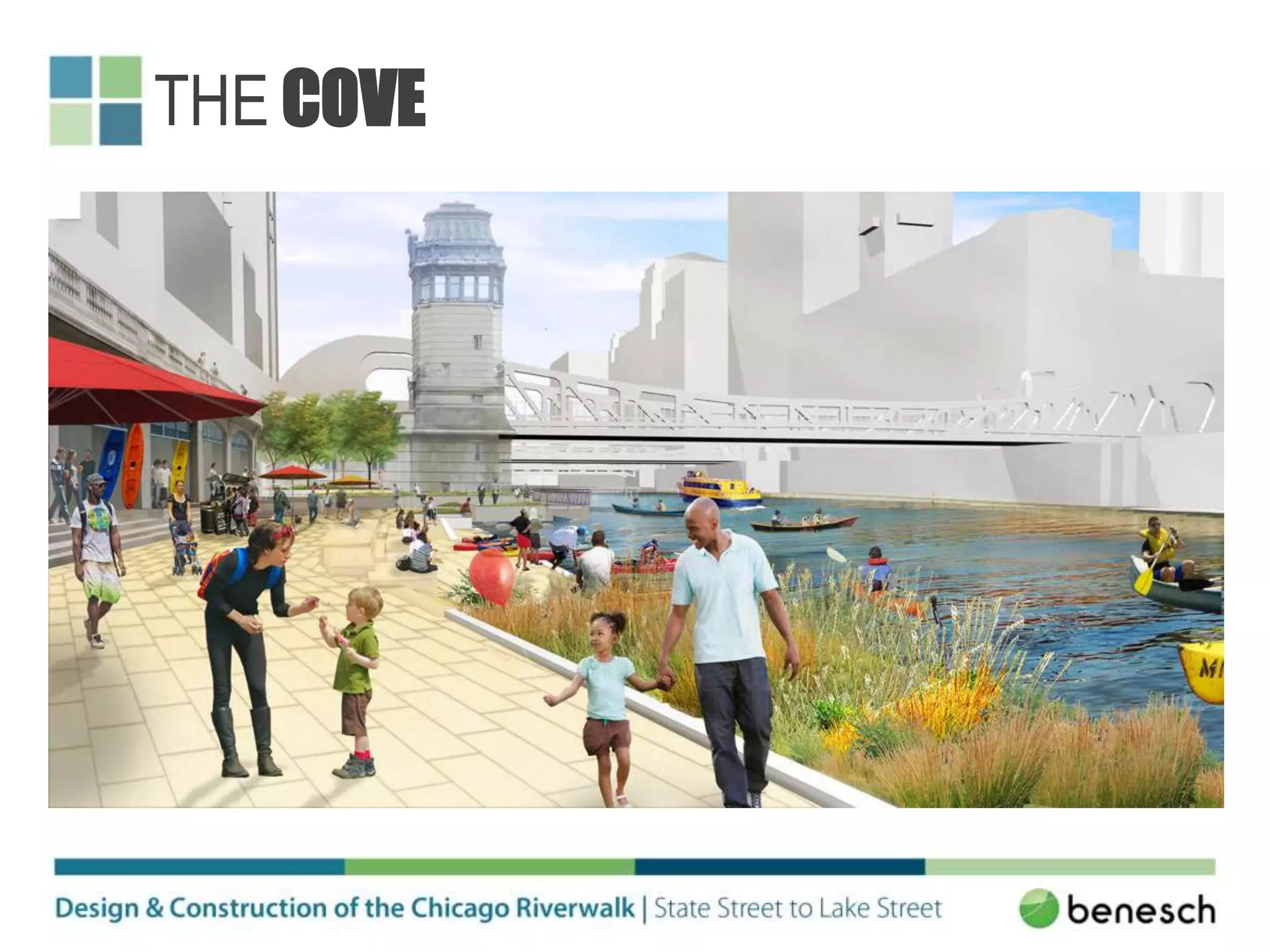
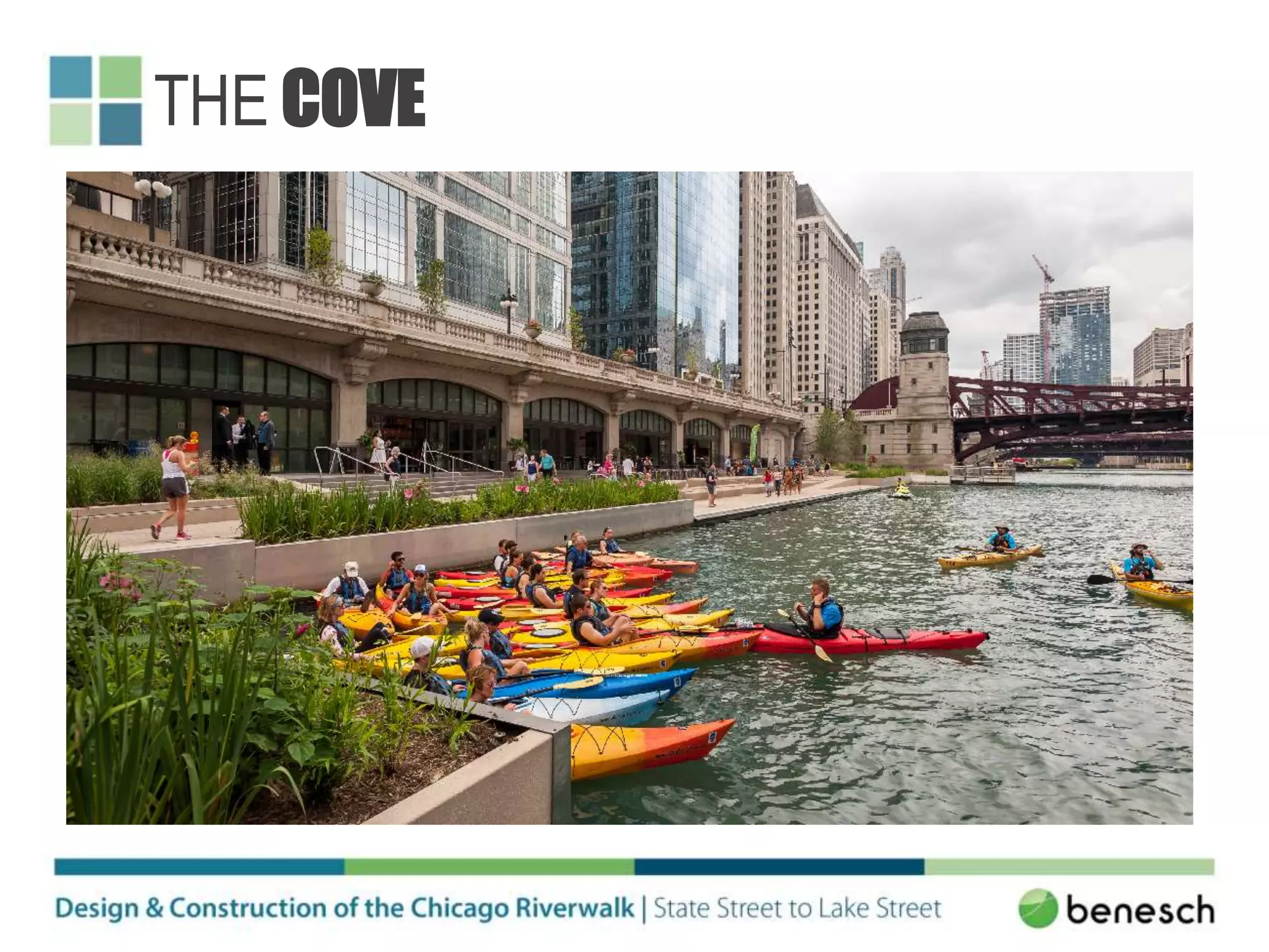
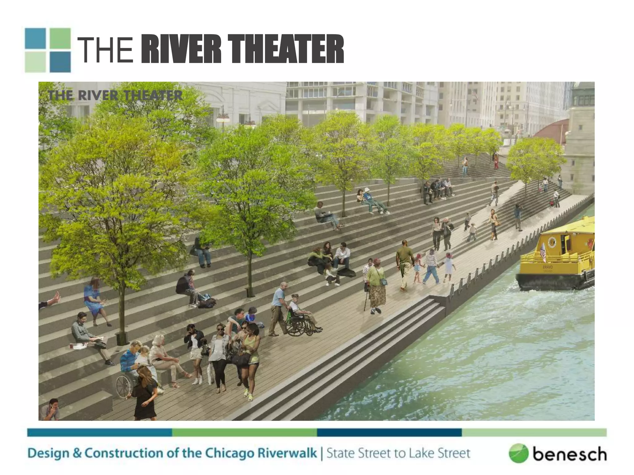
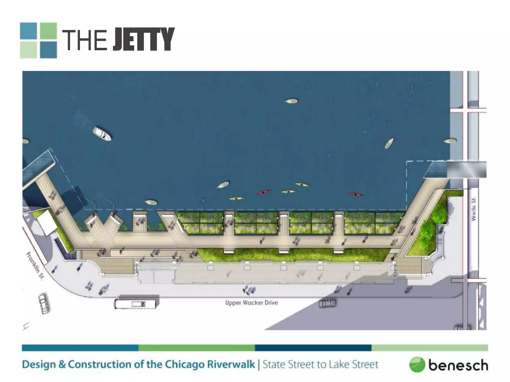
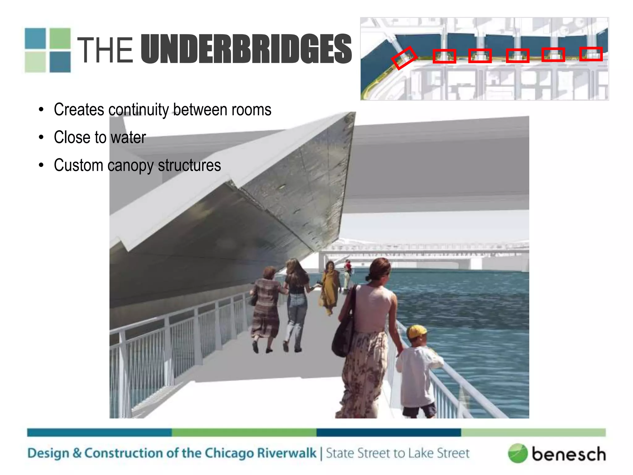
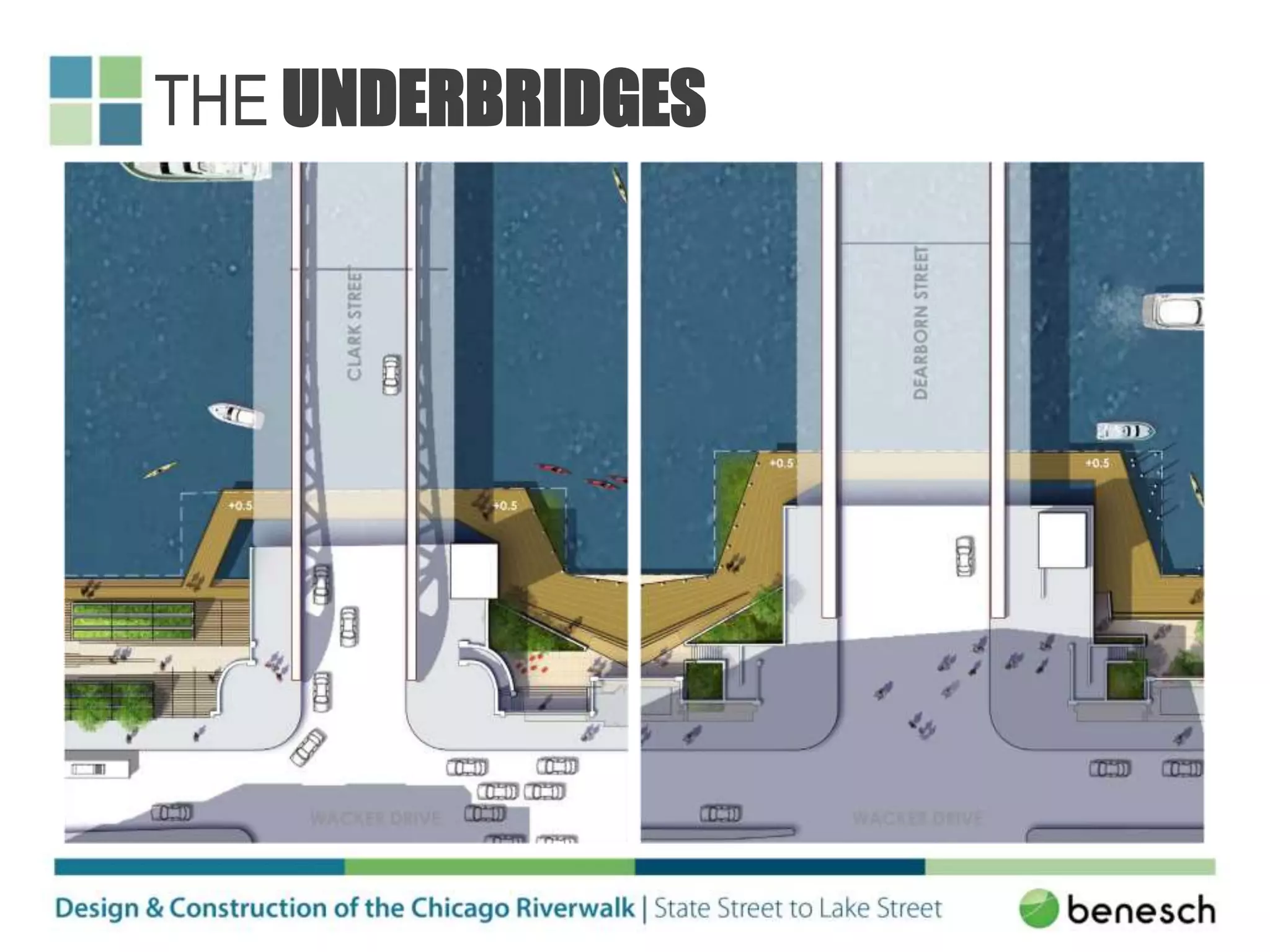
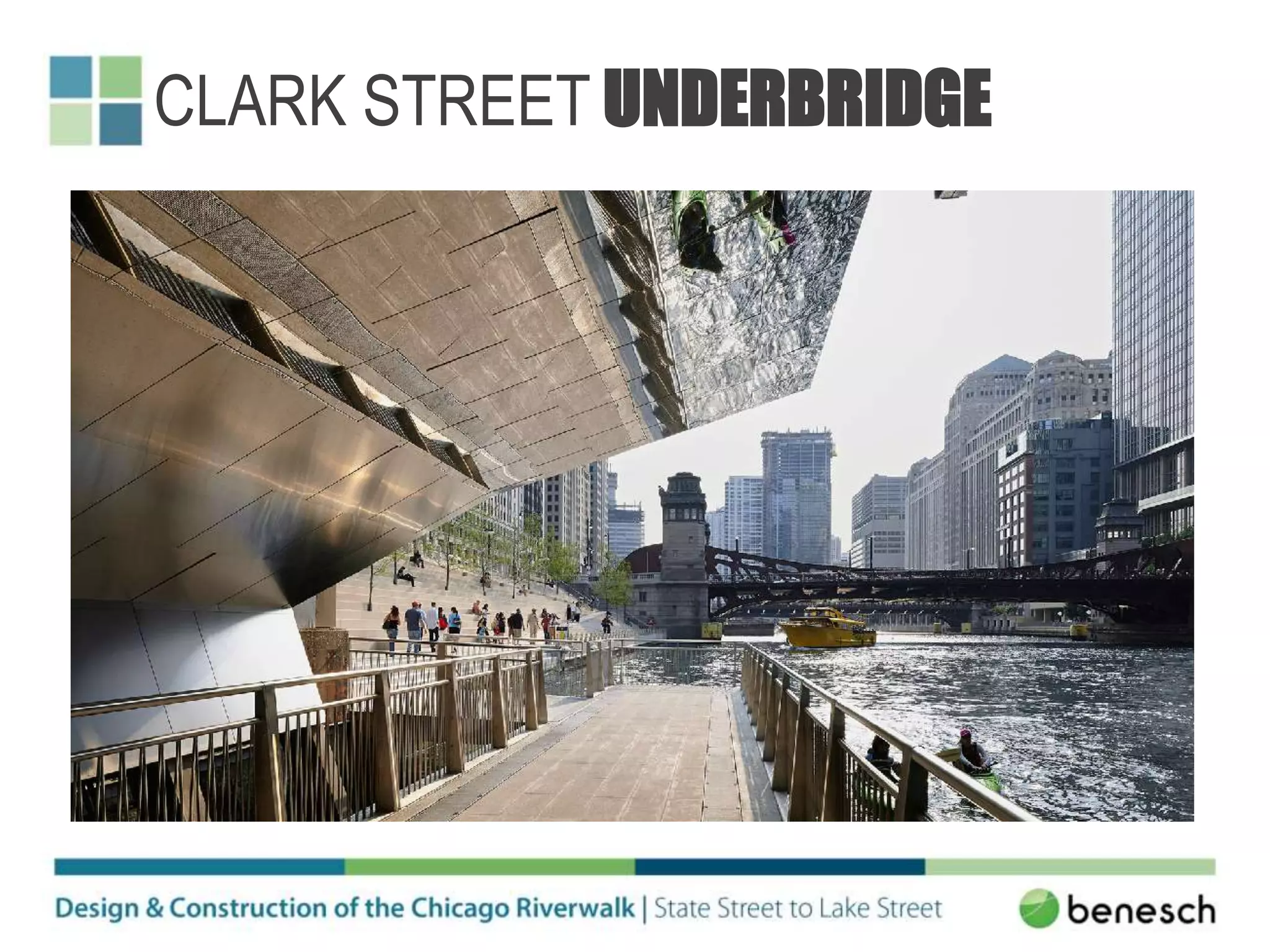
THE RIVERWALK DESIGN TEAM
THE RIVERWALK CONSTRUCTION MANAGEMENT TEAM
STAKEHOLDERS
• City of Chicago
• FHWA
• IDOT
• USACE
• USCG
• IDNR/ICMP
• IEPA
• MWRDGC
• CTA
• USFWS
• Illinois Historic Preservation Agency
• Building Owners
• Commercial & Tour Boat Operators
• Recreational Users/Boaters
• Retailers/Business Owners
• Utility Companies
• Community Groups
• Chicago Park District
• Local Residents
• Alderman
PROJECT GOALS
Mission
Develop the underutilized Riverwalk as a premier public space and continuous system.
Project Themes
• Cultural
• Environmental
• Economic
• Recreational
CULTURAL OBJECTIVES
• Create diverse gathering spaces
• Celebrate the River’s uniqueness
• Embrace the site’s history
• Enhance community life
ENVIRONMENTAL OBJECTIVES
• Restore aquatic habitat
• Cultivate terrestrial habitat
• Improve the water quality
• Use sustainable building strategies
ECONOMIC OBJECTIVES
• Maximize leasable opportunities
• Activate the space along the River
• Improve the perception of safety
• Support commercial boating activity
RECREATIONAL OBJECTIVES
• Create a continuous public walkway
• Improve vertical circulation
• Increase recreational boating
• Provide more public river uses
PROJECT STUDY HISTORY
1992
1995
1999
1999
2001
2002
2005
2006
2007
2008
2009
2009
PHASE 1
Michigan Ave. – State St.
2008 – 2009
Designers: RBA, Collins
Contractors: Walsh & Rausch
Const. Manager: Benesch
Cost: $19M
PHASE 2
State St. – LaSalle St.
2014 - 2015
Designers: Sasaki, RBA, Benesch
Contractor: Walsh
Const. Manager: Benesch
Cost: $43M
PHASE 3
LaSalle St. – Lake St.
2015 - 2016
Designers: Sasaki, RBA, Benesch
Contractor: Walsh
Const. Manager: Benesch
Cost: $53M
PROJECT PHASES
PROJECT FUNDING
Phase 1 – Michigan Avenue to State Street
• Central Loop tax-increment financing district (TIF)
Phases 2 & 3 – State Street to Lake Street
• Transportation Infrastructure Finance Innovation Act Program (TIFIA)
• Provides credit assistance for qualified infrastructure projects
• Intended only for projects of regional or national significance
• CDOT submitted letter of interest to the USDOT in 2012 for funding
• Loan maturity date is 2048
• Loan repayment methods:
• Rent / Leases
• Tour boats
• Private boats
• Charter boat docking
• Advertising
• Sponsorships
REGULATORY & PERMITTING
PROCESS
• The Chicago River is designated as “Waters
of the United States” and is protected by
federal law.
• The City was required to obtain permission
from Congress to construct the Riverwalk
into the river.
• On September 24, 2003, the U.S. House of Representatives
passed Water Resources Development Act H.R. 2557 allowing the
City to build:
 20 feet into the river beneath each bascule bridge (six total).
 25 feet between the bascule bridges.
 50 feet between Franklin and Lake Streets where the river
widens at the confluence of the three branches of the
Chicago River.
PERMITTING
Federal
USACE
• Section 404 (Clean Water Act) – Individual Permit
USCG
• Underbridge and Overall Project Sign-Off
• Initial Risk Assessment for USACE Permit
• Bridge Permit Application
• Bridge Lighting Permit Application
• Navigation Lighting Review
USFWS
• Threatened and Endangered Species Sign-Off
FHWA
• Notification of Adverse Effect and Memorandum of Agreement (MOA)
• Final Plan Review Sign-Off
State
IEPA
• Section 401 (Clean Water Act) – Water Quality Certification with Anti-
Degradation Report
• Stormwater Pollution Prevention Plan (SWPPP)
IDNR/ICMP
• ICMP Federal Consistency Determination & Certification + Part 3704
IDNR Permit
MWRDGC
• Hydraulic Analysis & Operations Report Sign-Off
• Sewer Permit for Sewer Connections/Structure Modifications
Illinois Historical Preservation Agency – State Historic Preservation Office
(SHPO)
• National Historic Preservation Act – Section 106 Sign-Off from
Advisory Council on Historic Preservation
City of Chicago
CDOT
• City of Harbor Permit
• Irrigation & Landscaping
DWM
• Proposed Sewer Design Sign-Off
• Water Supply Design Sign-Off
OUC
• Structures/Deep Foundations/Sheet Piling (Depth > 12 feet) Sign-Off
• New Sewers or Drainage Structures (Depth > 12 feet) Sign-Off
DEO
• Electrical & Lighting – Internal DEO plan review and approval
MOPD
• Internal plan review and approval
HED
• Landmarks Commission – Internal plan review and approval
Other
Wacker Drive Building Owners/Managers
• Verification of existing pipes and coordination/approval of proposed
pipe extensions and related work
CTA
• Underbridge Structure over CTA Red Line Tunnel at State Street
• Underbridge Structure under Wells Street – Brown & Purple Line
Tracks
• Marine Structure near CTA Blue Line Tunnel at Lake Street
PHASE 1 (COMPLETED 2009)
PHASE 1 (VIETNAM VETERANS
MEMORIAL)
PHASE 1 (MICHIGAN AVENUE)
PHASES 2 & 3 (EXISTING
CONDITIONS)
PHASES 2 & 3 (EXISTING
CONDITIONS)
Dearborn to ClarkState to Dearborn
Clark to LaSalle LaSalle to Wells
Wells to Franklin Franklin to Lake
PHASES 2 & 3 (EXISTING
CONDITIONS)
• River depth = 20 FT.
• Existing walkway width = 10 FT.
• Upper Wacker elevation = +22.0
• Existing dock elevation = +5.0 CCD
• Normal water elevation = -2.0 CCD
• Max. recorded water elevation = +4.1 CCD
• Modeled 100yr storm elevation = +6.4 CCD
EXISTING SUBSURFACE FACILITIES
THE RIVERWALK PLAN – PHASES 2 &
3
• 6 distinct blocks (“rooms”)
• Length of each room is approximately 300 feet except far west room
• Length of far west room is approximately 600 feet
THE RIVERWALK PLAN – PHASE 2
THE MARINA PLAZA
• Dining terrace / restaurant space
• Custom public seating
• Transition to Vietnam Veterans Memorial Plaza
THE MARINA PLAZA
THE MARINA PLAZA
THE MARINA PLAZA
THE COVE
• Kayak and rental space
• Facilitate human-powered watercraft docking
• Shallow edge allows easy access to river
THE COVE
THE COVE
THE COVE
THE RIVER THEATER
• Vertical access location
• Sculptured staircase/ramp (“stramp”)
• Boat/Water Taxi access
THE RIVER THEATER
THE RIVER THEATER
THE RIVER THEATER
THE RIVER THEATER
THE RIVERWALK PLAN – PHASE 3
THE WATER PLAZA
• Recreational space
• Interactive water features
• Zero-depth fountain and water jets
• High exposure to sunlight
THE WATER PLAZA
THE WATER PLAZA
• Ecological learning environment
• Promotes aquatic and celestial habitats
• Floating gardens
• Fishing piers and overlooks
THE JETTY
THE JETTY
THE JETTY
• Vertical access location
• Largest room
• 50’ build-out limit
• Largest green space/park
THE BOARDWALK
THE BOARDWALK
• Creates continuity between rooms
• Close to water
• Custom canopy structures
THE UNDERBRIDGES
THE UNDERBRIDGES
CLARK STREET UNDERBRIDGE
Structural Design
Challenges
PRIMARY STRUCTURAL DESIGN
CHALLENGES
• Expand the Riverfront
• Incorporate the existing dock wall and provide redundancy
• Poor soil conditions
• Maintain constructability in submerged conditions
• Crossing Beneath the Bascule Bridges
• Coast Guard design criteria for vessel collision
• Avoid existing tunnels and submarine cables
• Maintain constructability beneath/adjacent to the bridges
Typical Room Design Challenges
Expand the Riverfront
• Various systems from floating docks to pile-supported piers were
considered
• Tieback system selected for cost and proven performance
• Reuse the existing dock wall to minimize cost and construction
impacts
• System must have redundancy in the event of an existing tie rod
failure
• Riverwalk platform designed as structural slab on grade to alleviate
settlement concerns
• Address utilities that must extend and pass through new dock wall
• Consider the constructability of various elements that will ultimately be
underwater
Typical Room Plan View
Expand the Riverfront
Typical Room Cross Section
Expand the Riverfront
Assess the Existing Dock Wall
Expand the Riverfront
Connect New and Existing Systems
Expand the Riverfront
EXPAND THE RIVERFRONT
Jetty Plan View
Expand the Riverfront
Jetty Design Challenges
Expand the Riverfront
• Pier layout limited the choice of structural system
• Needed to avoid the existing tunnels beneath the river
• Same vessel collision criteria as the underbridges
• Must retain existing fill if existing timber piles and sheeting fail
Jetty Cross Section
Expand the Riverfront
Underbridge Design Challenges
Crossing Beneath the Bascule Bridges
• Miss submarine cables and existing tunnels
• Accommodate Coast Guard vessel collision criteria
• Maintain constructability
Typical Underbridge Plan View
Crossing Beneath the Bascule Bridges
Typical Underbridge Cross Section
Crossing Beneath the Bascule Bridges
Vessel Collision
Crossing Beneath the Bascule Bridges
• 1,622 kip force parallel to channel
• 811 kip force perpendicular to channel
Vessel Collision
Crossing Beneath the Bascule Bridges
• Marine Angel – Largest
vessel to traverse both the
Mississippi and Chicago
Rivers
• 500 ft long and 70 ft wide
Vessel Collision
Crossing Beneath the Bascule Bridges
Vessel Collision
Crossing Beneath the Bascule Bridges
• Envelope behavior with two separate analyses
• LUSAS finite element software
• L-Pile for nonlinear soil structure interaction
• Deflection was not deemed to be a critical limit state
• Underbridges will create a substantial improvement to the protection
of the existing bridge houses in the event of an impact
Vessel Collision at State Street
Crossing Beneath the Bascule Bridges
Vessel Collision at State Street
Crossing Beneath the Bascule Bridges
Vessel Collision at Jetty Pier
Expand the Riverfront
Constructibility
Crossing Beneath the Bascule Bridges
• Drilled shafts had to be drilled adjacent to and beneath the bascule
bridges
• Constructing the interior shafts requires bridges to be open and
remain open for extended periods of time
• Underbridge drilled shaft cap is halfway underwater and must be
placed in the dry
Drilled Shafts
Crossing Beneath the Bascule Bridges
Drilled Shafts
Crossing Beneath the Bascule Bridges
Drilled Shafts
Crossing Beneath the Bascule Bridges
Drilled Shaft Cap
Crossing Beneath the Bascule Bridges
“Bathtub” construction method chosen by Contractor
Drilled Shaft Cap
Crossing Beneath the Bascule Bridges
• Contractor proposed to
place the bottom and side
primary reinforcement
within the precast “bathtub”
• Need to achieve adequate
bond and horizontal shear
transfer to ensure section
behaves monolithically
rather than as two separate
members
• Bar splicers and grooves
Drilled Shaft Cap
Crossing Beneath the Bascule Bridges
Jacking Posts
Crossing Beneath the Bascule Bridges
CHICAGO RIVERWALK UNDER
CONSTRUCTION
CMAA Riverwalk Presentation

CMAA Riverwalk Presentation

  • 2.
  • 3.
  • 4.
    STAKEHOLDERS • City ofChicago • FHWA • IDOT • USACE • USCG • IDNR/ICMP • IEPA • MWRDGC • CTA • USFWS • Illinois Historic Preservation Agency • Building Owners • Commercial & Tour Boat Operators • Recreational Users/Boaters • Retailers/Business Owners • Utility Companies • Community Groups • Chicago Park District • Local Residents • Alderman
  • 5.
    PROJECT GOALS Mission Develop theunderutilized Riverwalk as a premier public space and continuous system. Project Themes • Cultural • Environmental • Economic • Recreational
  • 6.
    CULTURAL OBJECTIVES • Creatediverse gathering spaces • Celebrate the River’s uniqueness • Embrace the site’s history • Enhance community life
  • 7.
    ENVIRONMENTAL OBJECTIVES • Restoreaquatic habitat • Cultivate terrestrial habitat • Improve the water quality • Use sustainable building strategies
  • 8.
    ECONOMIC OBJECTIVES • Maximizeleasable opportunities • Activate the space along the River • Improve the perception of safety • Support commercial boating activity
  • 9.
    RECREATIONAL OBJECTIVES • Createa continuous public walkway • Improve vertical circulation • Increase recreational boating • Provide more public river uses
  • 10.
  • 11.
    PHASE 1 Michigan Ave.– State St. 2008 – 2009 Designers: RBA, Collins Contractors: Walsh & Rausch Const. Manager: Benesch Cost: $19M PHASE 2 State St. – LaSalle St. 2014 - 2015 Designers: Sasaki, RBA, Benesch Contractor: Walsh Const. Manager: Benesch Cost: $43M PHASE 3 LaSalle St. – Lake St. 2015 - 2016 Designers: Sasaki, RBA, Benesch Contractor: Walsh Const. Manager: Benesch Cost: $53M PROJECT PHASES
  • 12.
    PROJECT FUNDING Phase 1– Michigan Avenue to State Street • Central Loop tax-increment financing district (TIF) Phases 2 & 3 – State Street to Lake Street • Transportation Infrastructure Finance Innovation Act Program (TIFIA) • Provides credit assistance for qualified infrastructure projects • Intended only for projects of regional or national significance • CDOT submitted letter of interest to the USDOT in 2012 for funding • Loan maturity date is 2048 • Loan repayment methods: • Rent / Leases • Tour boats • Private boats • Charter boat docking • Advertising • Sponsorships
  • 13.
    REGULATORY & PERMITTING PROCESS •The Chicago River is designated as “Waters of the United States” and is protected by federal law. • The City was required to obtain permission from Congress to construct the Riverwalk into the river. • On September 24, 2003, the U.S. House of Representatives passed Water Resources Development Act H.R. 2557 allowing the City to build:  20 feet into the river beneath each bascule bridge (six total).  25 feet between the bascule bridges.  50 feet between Franklin and Lake Streets where the river widens at the confluence of the three branches of the Chicago River.
  • 14.
    PERMITTING Federal USACE • Section 404(Clean Water Act) – Individual Permit USCG • Underbridge and Overall Project Sign-Off • Initial Risk Assessment for USACE Permit • Bridge Permit Application • Bridge Lighting Permit Application • Navigation Lighting Review USFWS • Threatened and Endangered Species Sign-Off FHWA • Notification of Adverse Effect and Memorandum of Agreement (MOA) • Final Plan Review Sign-Off State IEPA • Section 401 (Clean Water Act) – Water Quality Certification with Anti- Degradation Report • Stormwater Pollution Prevention Plan (SWPPP) IDNR/ICMP • ICMP Federal Consistency Determination & Certification + Part 3704 IDNR Permit MWRDGC • Hydraulic Analysis & Operations Report Sign-Off • Sewer Permit for Sewer Connections/Structure Modifications Illinois Historical Preservation Agency – State Historic Preservation Office (SHPO) • National Historic Preservation Act – Section 106 Sign-Off from Advisory Council on Historic Preservation City of Chicago CDOT • City of Harbor Permit • Irrigation & Landscaping DWM • Proposed Sewer Design Sign-Off • Water Supply Design Sign-Off OUC • Structures/Deep Foundations/Sheet Piling (Depth > 12 feet) Sign-Off • New Sewers or Drainage Structures (Depth > 12 feet) Sign-Off DEO • Electrical & Lighting – Internal DEO plan review and approval MOPD • Internal plan review and approval HED • Landmarks Commission – Internal plan review and approval Other Wacker Drive Building Owners/Managers • Verification of existing pipes and coordination/approval of proposed pipe extensions and related work CTA • Underbridge Structure over CTA Red Line Tunnel at State Street • Underbridge Structure under Wells Street – Brown & Purple Line Tracks • Marine Structure near CTA Blue Line Tunnel at Lake Street
  • 15.
  • 16.
    PHASE 1 (VIETNAMVETERANS MEMORIAL)
  • 17.
  • 18.
  • 19.
    PHASES 2 &3 (EXISTING CONDITIONS)
  • 20.
    PHASES 2 &3 (EXISTING CONDITIONS) Dearborn to ClarkState to Dearborn Clark to LaSalle LaSalle to Wells Wells to Franklin Franklin to Lake
  • 21.
    PHASES 2 &3 (EXISTING CONDITIONS) • River depth = 20 FT. • Existing walkway width = 10 FT. • Upper Wacker elevation = +22.0 • Existing dock elevation = +5.0 CCD • Normal water elevation = -2.0 CCD • Max. recorded water elevation = +4.1 CCD • Modeled 100yr storm elevation = +6.4 CCD
  • 22.
  • 23.
  • 24.
    THE RIVERWALK PLAN– PHASES 2 & 3 • 6 distinct blocks (“rooms”) • Length of each room is approximately 300 feet except far west room • Length of far west room is approximately 600 feet
  • 25.
    THE RIVERWALK PLAN– PHASE 2
  • 26.
    THE MARINA PLAZA •Dining terrace / restaurant space • Custom public seating • Transition to Vietnam Veterans Memorial Plaza
  • 27.
  • 28.
  • 29.
  • 30.
    THE COVE • Kayakand rental space • Facilitate human-powered watercraft docking • Shallow edge allows easy access to river
  • 31.
  • 32.
  • 33.
  • 34.
    THE RIVER THEATER •Vertical access location • Sculptured staircase/ramp (“stramp”) • Boat/Water Taxi access
  • 35.
  • 36.
  • 37.
  • 38.
  • 39.
    THE RIVERWALK PLAN– PHASE 3
  • 40.
    THE WATER PLAZA •Recreational space • Interactive water features • Zero-depth fountain and water jets • High exposure to sunlight
  • 41.
  • 42.
  • 43.
    • Ecological learningenvironment • Promotes aquatic and celestial habitats • Floating gardens • Fishing piers and overlooks THE JETTY
  • 44.
  • 45.
  • 46.
    • Vertical accesslocation • Largest room • 50’ build-out limit • Largest green space/park THE BOARDWALK
  • 47.
  • 48.
    • Creates continuitybetween rooms • Close to water • Custom canopy structures THE UNDERBRIDGES
  • 49.
  • 50.
  • 51.
  • 52.
    PRIMARY STRUCTURAL DESIGN CHALLENGES •Expand the Riverfront • Incorporate the existing dock wall and provide redundancy • Poor soil conditions • Maintain constructability in submerged conditions • Crossing Beneath the Bascule Bridges • Coast Guard design criteria for vessel collision • Avoid existing tunnels and submarine cables • Maintain constructability beneath/adjacent to the bridges
  • 53.
    Typical Room DesignChallenges Expand the Riverfront • Various systems from floating docks to pile-supported piers were considered • Tieback system selected for cost and proven performance • Reuse the existing dock wall to minimize cost and construction impacts • System must have redundancy in the event of an existing tie rod failure • Riverwalk platform designed as structural slab on grade to alleviate settlement concerns • Address utilities that must extend and pass through new dock wall • Consider the constructability of various elements that will ultimately be underwater
  • 54.
    Typical Room PlanView Expand the Riverfront
  • 55.
    Typical Room CrossSection Expand the Riverfront
  • 56.
    Assess the ExistingDock Wall Expand the Riverfront
  • 57.
    Connect New andExisting Systems Expand the Riverfront
  • 58.
  • 59.
  • 60.
  • 61.
  • 62.
  • 63.
  • 64.
  • 65.
    Jetty Plan View Expandthe Riverfront
  • 66.
    Jetty Design Challenges Expandthe Riverfront • Pier layout limited the choice of structural system • Needed to avoid the existing tunnels beneath the river • Same vessel collision criteria as the underbridges • Must retain existing fill if existing timber piles and sheeting fail
  • 67.
  • 68.
    Underbridge Design Challenges CrossingBeneath the Bascule Bridges • Miss submarine cables and existing tunnels • Accommodate Coast Guard vessel collision criteria • Maintain constructability
  • 69.
    Typical Underbridge PlanView Crossing Beneath the Bascule Bridges
  • 70.
    Typical Underbridge CrossSection Crossing Beneath the Bascule Bridges
  • 71.
    Vessel Collision Crossing Beneaththe Bascule Bridges • 1,622 kip force parallel to channel • 811 kip force perpendicular to channel
  • 72.
    Vessel Collision Crossing Beneaththe Bascule Bridges • Marine Angel – Largest vessel to traverse both the Mississippi and Chicago Rivers • 500 ft long and 70 ft wide
  • 73.
  • 74.
    Vessel Collision Crossing Beneaththe Bascule Bridges • Envelope behavior with two separate analyses • LUSAS finite element software • L-Pile for nonlinear soil structure interaction • Deflection was not deemed to be a critical limit state • Underbridges will create a substantial improvement to the protection of the existing bridge houses in the event of an impact
  • 75.
    Vessel Collision atState Street Crossing Beneath the Bascule Bridges
  • 76.
    Vessel Collision atState Street Crossing Beneath the Bascule Bridges
  • 77.
    Vessel Collision atJetty Pier Expand the Riverfront
  • 78.
    Constructibility Crossing Beneath theBascule Bridges • Drilled shafts had to be drilled adjacent to and beneath the bascule bridges • Constructing the interior shafts requires bridges to be open and remain open for extended periods of time • Underbridge drilled shaft cap is halfway underwater and must be placed in the dry
  • 79.
  • 80.
  • 81.
  • 82.
    Drilled Shaft Cap CrossingBeneath the Bascule Bridges “Bathtub” construction method chosen by Contractor
  • 83.
    Drilled Shaft Cap CrossingBeneath the Bascule Bridges • Contractor proposed to place the bottom and side primary reinforcement within the precast “bathtub” • Need to achieve adequate bond and horizontal shear transfer to ensure section behaves monolithically rather than as two separate members • Bar splicers and grooves
  • 84.
    Drilled Shaft Cap CrossingBeneath the Bascule Bridges
  • 85.
    Jacking Posts Crossing Beneaththe Bascule Bridges
  • 86.