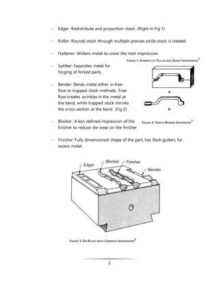
The document summarizes the closed die forging process. It discusses the main processes including die impressions, flashing design, and lubrication. It also covers production materials focusing on part shape, die tolerance, and hot vs cold forging. The document examines how forging affects material properties through grain flow orientation and defects that can occur. Key forged products like connecting rods and crankshafts are also highlighted.


![9
𝑟 =
1
20
∙ ℎ Equation 3
with the first equation being for h<100mm and the second
120mm<h<250mm.
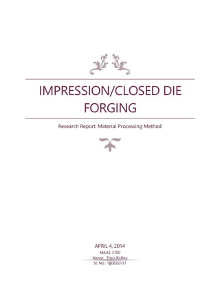
2.3 Hot vs Cold Forging
Closed die forgings can be produced in hot or cold forging. Though most
forged products are from hot forging, cold forging can be used to make
stronger products.
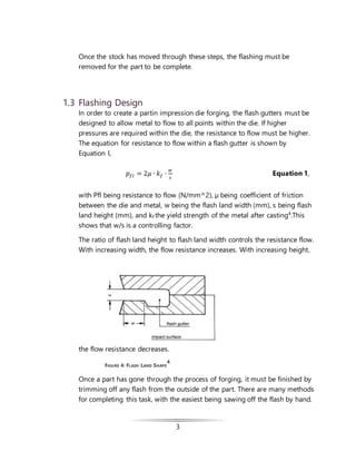
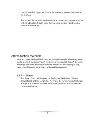
The difference can be shown by examining a cylindrical billet undergoing
frictionless upsetting during hot and cold forging using the Hollomon
equation
𝜎𝑡 = 𝐾 [ln (
𝐴 𝑜
𝐴1
)]
𝑛
Equation 3
where σt is true stress(or flow stress), Ao is the original cross sectional area,
A1 is the area after deformation, K is the material strength constant, and n
is the strain hardening exponent.5
This works with the fact that a material
with a higher strain hardening exponent n will strain harden quickly while
FIGURE 10: DEFORMATION OF BILLET IN AXISYMMETRIC DIE
3](https://image.slidesharecdn.com/a0c28739-c2ab-46f9-9c52-fc53d48fea2c-150421111456-conversion-gate01/85/Closed-Die-Forging-Report_revisionsEve-14-320.jpg)

![17
References
[1] J.A.Rossow, "Closed Die Forgings," ASM Handbook, vol. 1, no. 10, p. 337–357, 1990.
[2] R. Shivpuri, "Dies and Die Materials for Hot Forging," ASM Handbook, vol. 14A, pp.
47-61, 2005.
[3] A. K. Khare, "Forming and Forging," ASM Handbook, vol. 14A, p. 111–118, 2005.
[4] H. Tschaetsch, "Impression-Die Forging (Closed-Die Forging)," in Metal Forming
Practice: Processes - Machines - Tools, Dresden, Springer, 2006, pp. 123-139.
[5] J. Beddoes, "4.3 Forging," in Principles of Metal Manufacturing Processes,
Burlington,MA, Elsevier Butterworth-Heinemann, 1999, pp. 103-115.
[6] T. Altan, G. Ngaile and G. Shen, "Friction & Lubrication," in Cold and Hot Forging
Fundamentals and Apllications, Materials Park, ASM International, 2005, pp. 67-74.
[7] W. Naujoks and D. C. Fabel, "Forging Practice," in Forging Handbook, Cleveland, OH,
American Society for Metals, 1939, pp. 106-205.
[8] W. Naujoks and D. C. Fabel, "Forge Dies and Tools," in Forging Handbook, Cleveland,
OH, American Society for Metals, 1939, pp. 87-105.](https://image.slidesharecdn.com/a0c28739-c2ab-46f9-9c52-fc53d48fea2c-150421111456-conversion-gate01/85/Closed-Die-Forging-Report_revisionsEve-22-320.jpg)


![Forging Process. [Workshop Practices]](https://cdn.slidesharecdn.com/ss_thumbnails/forging-metal-131007035538-phpapp01-thumbnail.jpg?width=640&height=640&fit=bounds)


![Ch07[1]](https://cdn.slidesharecdn.com/ss_thumbnails/ch071-141226001133-conversion-gate01-thumbnail.jpg?width=640&height=640&fit=bounds)


