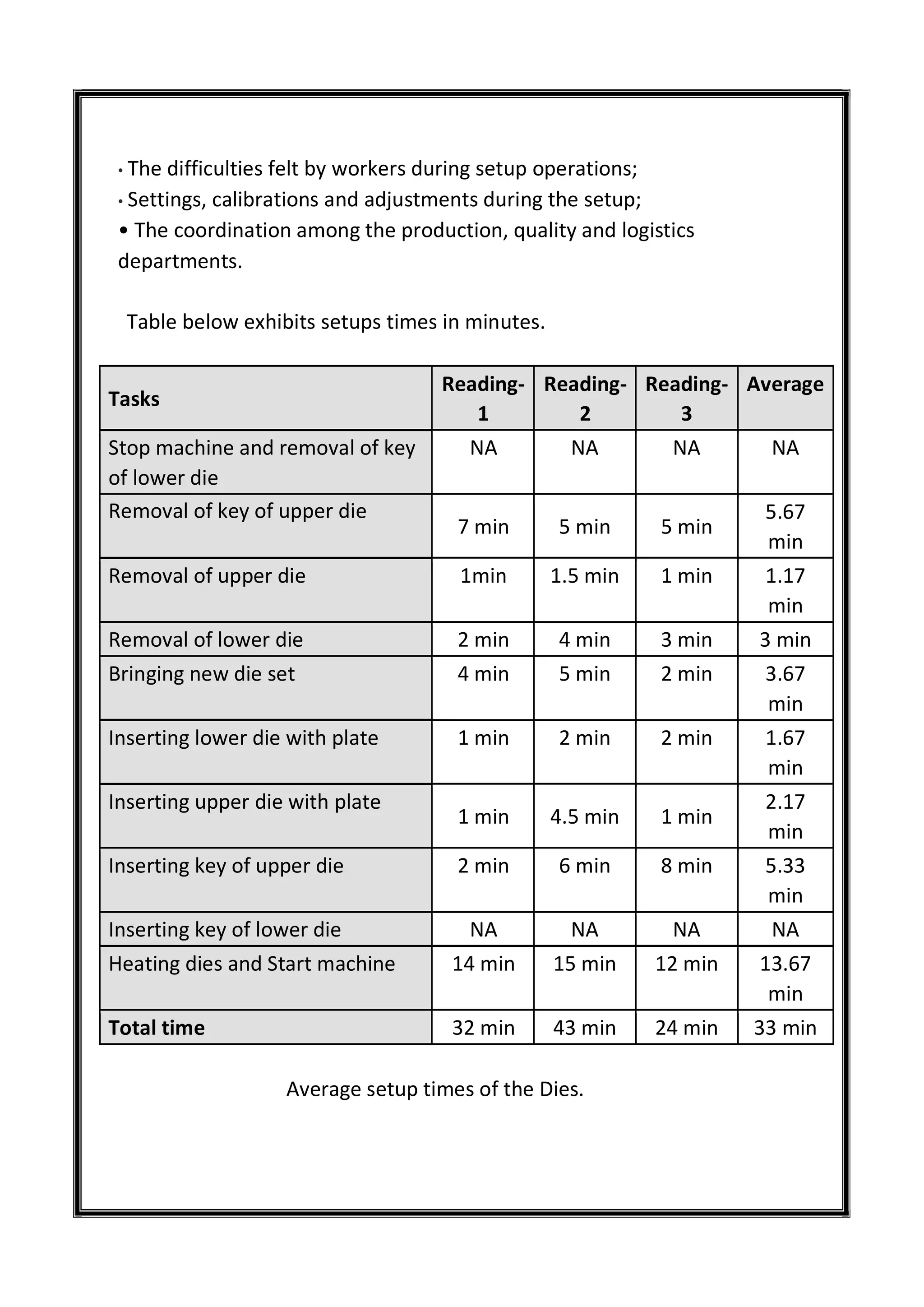
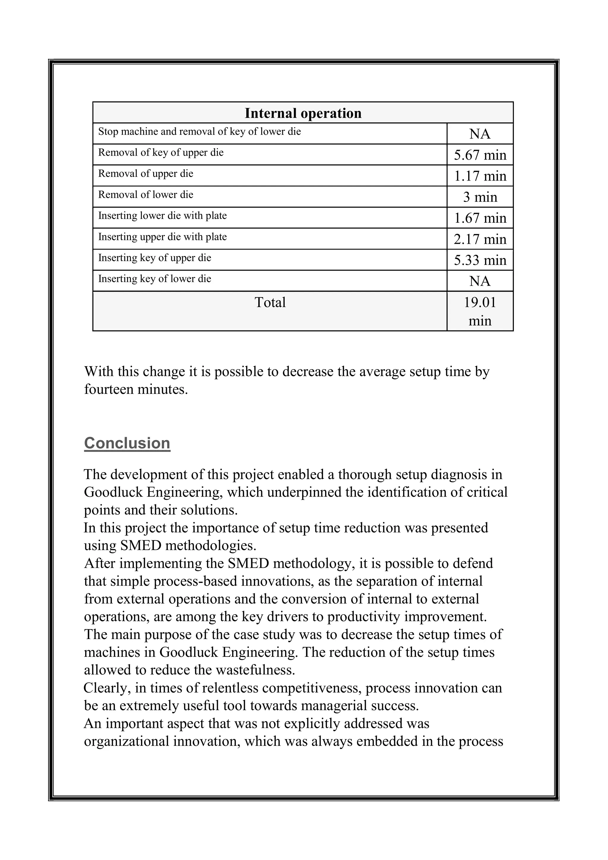
College Call Girls Nashik Nehal 7001305949 Independent Escort Service Nashik
Â
SMED
1. INDUSTRIAL TRAINING REPORT
ON
“SINGLE MINUTE EXCHANGE OF DIE (SMED)
IN CLOSED DIE FORGING”
SUBMITTED TO: SUBMITTED BY:
MR. B.R.PATOLE ALOK GUPTA
(VP-PRODUCTION) ABHISHEK SINGH RATHORE
2. ACKNOWLEDEMENT
It has been honor and privilege to do industrial training on the subject
SINGLE MINUTE EXCHANGE OF DIE (SMED). I take this an
Opportunity to communicate my sincere thanks and regards to
everyone who had contribute to industrial training and helped me
successfully completion.
This project report couldn’t have been completed without the guidance
of our project guide MR. B.R.PATOLE.
We express our sincere thanks and gratitude to those who have helped
directly or directly.
At last we are thankful to production in-charge MR. BHATI to give
us an opportunity to experience the concrete reality of the project.
ALOK GUPTA
ABHISHEK SINGH RATHORE
KIET, GHAZIABAD
3. TABLE OF CONTENTS
S.NO CONTENTS
1. About the company
2. Clientele
3. Factory tour
4. Processing
5. About forging and its types
6. Processing flow chart
7. Forging machines
8. Quick die exchange
9. SMED
4. GOOD LUCK ENGINEERING CO.
ABOUT
Good Luck Engineering Co. a unit of Good Luck Steel Tubes Limited is
one of the leading manufacturer of open and close die steel forgings.
An ISO 9001:2008 company, having a government recognized export
house having silver seal status and also holding the membership of
FIEO, FII and have also received many export excellence awards.
CLIENTELE
Company have a renowned name as the exporter of quality steel
forgings across the globe. They have their clientele spread over 90
countries that include UK, Singapore, South Africa, Oman, UAE,
5. Australia, New Zealand, East & West Africa, Latin America, Trinidad,
Ghana, Haiti, Ethiopia, Sri Lanka and Madagascar. They also offer
their range of products to domestic clients include reputed names
from Public and Private sector like OEMs and Central & State
government Department.
FACTORY TOUR
PROCESSING
WHAT IS THE FORGING PROCESS?
Forging is a process that results in a variety of changes within the
properties of the metal. A forging can be produced by several
methods, all of them require shaping the metal by plastic
deformation. The most common used forging process is impression
die or precision forging. There is great variation the temperature and
processes required in different methods of forgings. A product can be
forged by three different methods, namely cold, warm and die
6. forging depending on its requirements.
A forging process, which requires drawing out the metal results in
increased length and a decrease in the cross-section whereas
upsetting the metal results in the opposite. Squeezing of metal in
closed impression dies bring change in length, cross-section, and in
overall favorable grain flow.
HOW DOES FORGING DIFFER FROM CASTING?
The major difference between forging and casting is that forging can
be done to cold, warm and hot metal depending on the requirement
of the final product. However the metal is never completely melted
and poured into a die whereas casting involves pouring of molten
metal into a mold for cooling.
MECHANICAL BEHAVIOUR OF METALS
Deformation of a solid body can be classified as elastic or plastic:
when unloaded, an elastically deformed body always returns to its
original shape regardless of history, rate, time, and path of loading;
the plastic deformation of a body, on the other hand, depends on all
these variables and is subjected to (permanent) loss of original shape
when unloaded. Although the theory of elasticity is well established
and yields accurate predictions of strain (due to mechanical stress),
the theory of plasticity normally yields approximate solutions to
plastic deformation problems.
The typical one-dimensional stress–strain curve shown in Fig. 1a
for a tension test would normally be also applicable to the
compression of ductile metals. As a load is applied on a metal part, it
elongates in a linear proportion to the force until the stress level
reaches the yield stress value, Y. At this critical point, when the load
is released, the strain level of the part would be 0.2% or less. At any
point before that, the part would completely recover its original
shape. As the load is increased beyond the yield stress value, the part
7. undergoes plastic deformation in a uniform-elongation phase until
the stress level reaches the ultimate tensile strength value, UTS. At
any point during this phase, if the load is removed, the part would
recover the elastic strain portion of the deformation but permanently
maintain the plastic elongation (or shortening in the case of
compression) (Fig. 1b).
FIGURE 1 (a) Stress–strain curve for tension. (b) Loading-unloading cycle for plastic deformation: F, force; Ao, cross-
sectional area; lo, part’s original length; D l, incremental elongation.
Beyond the UTS stress level, the continuing application of load would
lead to non-uniform elongation and eventual fracture of the part. In
this context, ductility is the percentage of plastic deformation that
the part undergoes before fracture.
As mentioned above, in metal forming the preference would be
to process materials whose ductility is high (and that could be made
even higher with increased temperature). Another important factor
that we must take note of in metal forming is the rate of deformation
(i.e., the amount of strain per unit time). It has been accepted that as
the rate of deformation is increased, so would the necessary amount
of stress to induce the required strain rate. As the temperature of the
part is increased, however, one can obtain higher rates of
deformation. Thus one can conclude that increasing temperature
raises ductility, lowers yield stress, and thus shortens forming cycle
times.
8. Forging
Forging is one of the oldest metal forming processes; it can be traced
to early civilizations of Egypt, Greece, Persia, China, and Rome, when
it was used in the making of weapons, jewellery, and coins. Forging,
however, became a mainstream manufacturing process in the 18th
century with the development of drop-hammer presses. Today, in
closed-die forging, a part can be formed under compressive forces
between the two halves of a die, normally in several steps, or in one
step (with or without flash). The thin flash formed during closed-die
forging cools quickly and acts as a barrier to further outward flow of
the blank material, thus, forcing it to fill the cavity of the die.
Closed die forging (a) with flash; (b) without flash.
Forging is a process in which metal billets are plastically deformed by
compressive forces, normally within closed dies. Today, forging is the
most common metal forming process for the fabrication of discrete
solid (versus thin-walled) parts: connecting rods for the automotive
9. industry, shafts for aircraft turbines, and gears for a variety of
transportation equipment. Forged parts, small or large, although
formed into net shape geometries, generally, require additional
finishing operations for dimensional as well as mechanical properties
improvements. Forging operations can be performed either cold or
hot. Cold forging at room temperature requires greater forces than
hot forging but yields much better dimensional accuracy and surface
finish.
Closed Die Forging
In closed die forging, also known as impression-die forging, the billet
acquires the shape of the cavity formed between the two halves of
the die when closed under pressure. The process is commonly carried
out in several steps to reduce significantly the amount of force at
each formation step and to minimize the possibility of defects as well
as the amount of waste material (flash). The division of the overall
objective into a smaller number of tasks is part geometry and
material dependent.
(a) Fullering; (b) edging.
The first task in closed die forging is the careful preparation of
the billet/blank: it may be cut from an extruded bar or received
directly from a casting process; subsequently, it is subjected to a
preshaping process, normally through open die forging, when the
material is distributed to different regions of the billet. Fullering
10. distributes material away, while edging gathers it into an area/region
of interest. An important preparatory step in the forging process is
lubrication through spraying (1) of the die walls with molybdenum
disulfide or other lubricants for hot processes and (2) of the blank’s
surface with mineral oils for cold processes.
Built-in automation is widely utilized in closed die forging for the
transfer of preforms from one cavity into another, commonly within
the same die/press, as well as for the spraying of the die walls with
lubricants. External industrial robotic manipulators have also been
used in the placement of billets/blanks into induction furnaces for
their rapid heating and their subsequent removal and placement into
hot forging presses. Except in cases of flash less forging, these
manipulators can also transport the parts into flash trimming and
other finishing machines.
OPEN DIE FORGING
The Open Die Forging is done with hammers and presses of metals
like stainless steel, carbon steel and alloy steel. It is a modern-day
extension of the pre-industrial metalsmith working with a hammer at
his anvil. In this process the metal to be forged is not completely
confined as it is being shaped by the dies. The open die process is
generally used for large parts like shafts, sleeves, disks etc.
MOST OF THESE FORGINGS ARE PRODUCED ON FLAT DIES. ROUND
SWAGING DIES AND V DIES ALSO ARE USED IN PAIRS OR WITH A
FLAT DIE. OPERATIONS PERFORMED ON OPEN DIE PRESSES
INCLUDE:
Drawing out or reducing the cross-section of an ingot or billet to
lengthen it. Upsetting or reducing the length of an ingot or billet to a
larger diameter. Upsetting, drawing out, and piercing--processes
sometimes combined with forging over a mandrel for forging rough-
11. contoured rings.
In the open die forging as the metal piece required to be forged is
hammered or pressed, it is repeatedly manipulated between the dies
till final forged dimensions are reached. The forged part is rough
when machined is followed by finishing machine to final dimensions.
The increase use of press and hammer control makes open die
forging a more automated process.
In this type of forging, metals are worked above their recrystallization
temperatures. As the process requires repeated changes in metal
piece positioning, it cools during open die forging below its hot-
working or recrystallization temperature and hence is reheated
before forging can continue.
We follow a thumb rule in open die forging of steel, that 50 lb of
falling weight is required for each square inch of stock cross-section.
Compression between flat dies, or upsetting, is an open die forging
process in which an oblong metal piece is placed on end of a lower
die and its height is reduced by the downward movement of the top
die. Friction between end faces of the metal piece and dies prevents
the free lateral spread of the metal, which results in a typical barrel
shape. The then contact with the cool die surface chills the end faces
and hence increases its resistance to deformation and enhanced
barreling.
Upsetting between parallel flat dies are restrained to deforming
symmetrical around a vertical axis. In case preferential elongation is
desired, compression between narrow dies is ideal. Frictional forces
in the axial direction of the bar are smaller than in the perpendicular
direction, and material flow is mostly axial.
A narrower die elongates better, but if too narrow, the die will cut
the metal instead of elongating. The direction of material flow can
also be regulated by use of dies with specially shaped surfaces.
12. Compression between narrow dies are not a continuous process
since many strokes must be executed while the metal piece is moved
in an axial direction. Roll forging can be used to make this task
continuous.
Roll in large size cause greater lateral spread and less elongation as
there is greater frictional difference in the arc of contact when
compared to smaller rolls which elongate more.
PROCESSING FLOW CHART
In Open Die Forging process, for manufacturing products like forged
flanges, forged rings etc., in metals like stainless steel, carbon steel
and alloy steel. Following is the process of forging:
INGOT OR BLOOM
In Ingot or bloom process hot working in a continuous-cast bloom or a
steel ingot is done on the metal to be forged. The process comprising
the steps of three steps; in the first step cooling the bloom followed by
quenching the bloom and the last step involves heating the bloom or
the steel ingot in a furnace which is followed by hot shaping.
BAND SAW
A band saw involves complex coordination between tilting motion
and a translational motion of the metal piece and the band saw blade,
so that a curved cut is made in the metal piece
13. CUT PIECES
We have the right equipment, to cut pieces in the required dimensions.
The machines are well maintained to offer best products to the
clients.
PRE- HEATING FURNACE
A preheating furnace is used for metal in shapes like bars, billets, and
the likes of metal. It has a furnace tunnel formed by furnace shells for
preheating the metal. Their central range of the furnace shells are
covered by a heat insulation which comprises removable designed
insulation members.
FORGING
In this step forging is done via forging machines which is disclosed
for reducing the cross sectional area of the metal piece, laced on the
forging axis of the forging machines
ULTRA SONIC NORMALIZING
This method is used for determining and evaluating physical
characteristics of a material. In this method complex ultrasonic waves
are created in the metal. The waves formed may be of any
combination of the wave types and modes and they are not limited to
fundamental plate modes.
MACHINE SHOP
We have the required machines to conduct the process of forgings
with precision and accuracy. We have latest technology and machines
that give accurate forgings. Our staff is well trained, to use the
machines and maintain them as well.
HEAT TREATMENT PROCESS
In the heat treatment process Quenching and Tempering for Metal
Forging, Annealing Steel and Metal Forgings is conducted. These
process are conducted to maintain the balance of ductility and strength
of the metal. The description of these processes is as follows:
14. QUENCHING AND TEMPERING FOR METAL FORGING
Metal Forgings that have been quenched and tempered, posses a good
balance of strength and ductility. The steel forgings are constantly
cooled in water, oil, or saltwater bath, which increases their hardness.
To restore softness within the metal forgings, the forgings are then
tempered to prevent snapping or shattering.
ANNEALING STEEL AND METAL FORGINGS
Annealed of the forgings is done to recover the ductility and yield
strength, which were lost during the hot forging process such as closed
die forging or hand forging. Forgings that have to be annealed are first
softened to relive internal stress, than recrystallized to grow new,
more refined grains.
MARKING AND PARKING
In the last step, we mark the forged metal piece according to their
grades and other specifications to maintain traceability and then the
final product is then parked for packaging and delivery.
FORGING MACHINES
Presses and hammers are used in the forging of discrete parts. They
are primarily chosen according to the part geometry and material as
well as production rates. Hydraulic mechanical, and screw presses are
used for both hot and cold forging, while hammers are mostly used in
hot forging.
HYDRAULIC PRESSES
Hydraulic presses can be configured as vertical or horizontal machines
and can operate at rates of up to 1.5 to 2.0 million parts per year.
Although they operate at much lower speeds than do mechanical
presses, the ram speed profile can be programmed to vary during the
stroke cycle.
15. MECHANICAL PRESSES
Mechanical presses can also be configured as vertical or horizontal.
The driver system (crank or eccentric) is based on a slider–crank
mechanism. Since the ram is fitted with substantial guides and since the
press is a constant stroke machine, mechanical presses yield better
dimensional accuracy than do hammers. Knuckle joint (mechanical)
presses that can produce larger loads for short stroke lengths are often
used for cold coining operations. The primary power sources for large
mechanical presses are DC motors.
SCREW PRESSES
Screw presses utilize a friction, gear transmission, electric or hydraulic
drive to accelerate a flywheel–screw subassembly for a vertical stroke.
In the most common friction drive press, two driving disks (in
continuous
(a) Mechanical forging press; (b) screw press.
motion) are utilized to engage a flywheel through friction (one disk at a
time, for upward and downward motion). The flywheel, in turn,
accelerates the screw attached to it in a downward/upward motion,
where maximum speed is achieved at the end of the stroke.
16. HAMMERS
A hammer press is a low-cost forging machine that transfers the
potential energy of an elevated hammer (ram) into kinetic energy that is
subsequently dissipated (mainly) by the plastic deformation of the part.
The two most common configurations are the gravity-drop hammer and
the power-drop hammer. As the name implies, the former utilizes only
gravitational acceleration to build up the forging energy. The latter type
supplements this energy through the utilization of a complementary
power source—most commonly hydraulic—for increased vertical
acceleration.
The selection of a suitable forging machine for the task at hand is
influenced by several factors: part material and geometry and desired
rate of deformation (i.e., strain rate). Hydraulic presses can achieve a
stroke speed of up to 0.3 m/s and apply a force of typically up to 500
MN in closed die forging. Mechanical presses can achieve a stroke
speed of up to 1.5 m/s and apply a force of typically up to 100 MN. (A
power-drop hammer, in contrast, can achieve a stroke speed of up to 9
m/s.) Presses are normally preferred for more ductile materials than
those for hammers (e.g., aluminum versus steel).
Hammers for forging
17. QUICK DIE EXCHANGE
Tactical flexibility in manufacturing requires companies to respond to
market demand fluctuations in a timely and profitable manner. A key
requirement is to have operational flexibility on the factory floor,
whereby production models and batch sizes of parts can be varied
without disruptions. Productivity gains can be achieved in such
environments by having common setup tools and procedures, so that
setup transformation from one part model to another does not require
an excessive amount of time.
In this section, we will briefly review the topic of quick die
exchange, which is at the heart of productivity improvement through
the elimination of waste (i.e., activities that do not add value to the
product). In this context, the single-minute exchange of dies (SMED)
philosophy proposed by S. Shingo stands out as an excellent starting
point. Shingo’s SMED approach is a vital part of a comprehensive
manufacturing strategy that he has advocated since the early 1950s:
stockless production, the minimization of in-process inventories. SMED
is a companion to justin-time (JIT) manufacturing and defect-free
production tactics in this quest. Many hundreds of applications of the
SMED philosophy around the world have reduced setup times from
several hours to a few minutes, especially in environments of metal
forming, metal casting, and plastics molding.
Single Minute Exchange of Die
Introduction
The last two decades have been witnessing great changes in the
management and organization of the production systems in industrial
firms all around the world. Two important innovations underpinned
these changes: the technological revolution and the proposition of new
managerial philosophies. The former is felt throughout the world due to
18. new information systems, machinery, telecommunications, pervasive
automation and robotics, that underpinned unprecedented productivity
gains and better operations planning and control. The latter allowed a
larger focus on internal resources as most of the firms realized that the
qualification of their human resources constitute a strong differentiating
element in making the firms faster and more flexible in the business
world.
The SMED (Single Minute Exchange of Die) methodology,
developed by Shingo (1985), was developed in order to reduce and
simplify the setup time during change-over. SMED, which is also a
Japanese process-based innovation, makes it possible to respond to
fluctuations in demand and results in lead time reductions, while also
eliminating wastefulness during change-over and diminishing lot
sizes.
Traditionally firms regarded setup times as one of the most expensive
costs they had to face and opted for both the minimization of the
number setups implemented and for very large production lots. This
method contributed to an excessive inventory because they produced
more than they needed to satisfy customer needs. Nowadays the general
understanding is that mass production has become obsolete as
production costs have increased and efficiency has decreased steadily.
Today firms are forced to compete, simultaneously, in terms of price,
product quality, product differentiation and delivery time. To improve
production processes it is necessary to analyse the value added by each
activity and eliminate all those that do not add value to the product,
which makes the SMED methodology extraordinarily important.
Firms that produce a large diversity of products have to implement
production processes that are capable of satisfying all of the customers’
needs. Frequently, the time necessary for the company to implement its
setup operations limits the firm’s capacity to satisfy its customers’
needs. Nowadays, with the large diversity of products necessary for the
same demand, firms are forced to produce smaller lots without harming
their global productivity. Thus, firms must be capable of producing a
large diversity of products in small quantities and, consequently, must
provide for much more frequent tool changes. In order to compete,
firms have to find ways to reduce setup times, eliminate wastefulness
19. and non-added value activities and convert idle setup time into regular
production time, which means that a strong focus on process innovation
is needed.
Having identified the main problem, the firm’s challenge is to minimize
the setup times, which can be accomplished following the SMED
methodology. In order to implement this process-based innovation,
setup operations have to be standardized and properly documented in
order to ensure that production workers follow all of the parameters of
that process.
Literature Review
Single-Minute Exchange of Die (SMED) refers to the theory and
techniques used for the reduction of equipment setup times. SMED
has as its objective to accomplish setup times in less than ten
minutes, i.e. a number of minutes expressed by a single digit.
Although not all setups can be literally reduced to this time, between
one and nine minutes, this is the goal of the SMED methodology.
SMED, also known as Quick Change over of Tools, was developed
by Shingo (1985), who characterized it as a scientific approach for
the reduction of setup times, and which can be applied in any
industrial unit and for any machine. SMED is defined as the
minimum amount of time necessary to change the type of production
activity taking into consideration the moment in which the last piece
of a previous lot was produced vis-Ă -vis the first piece produced by
the subsequent lot. Before the development of the SMED
methodology, the best way to minimize the cost of idle machines
during setup operations was to produce large lots, in order to obtain
the lowest possible percentage of idle time per unit produced.
According to Min and Pheng (2007), the ideal amount of each
production lot was obtained when the inventory costs equalled the
costs of idle equipment during the changeover of tools.
Toyota came across this problem because inventory costs for their
vehicles were extremely high. Before this problem, the best way to
reduce the amount of production loss was to reduce setup times.
20. Thus, if production changes could be done in less time, the ideal
amount of production could be smaller, which, consequently, would
decrease the costs involved. The question around the optimum
amount of the production lot remains as it is necessary to calculate
the minimum amount for each production lot. The production of large
lots also has inherent capital costs with the amount invested in
inventory. If we add to this inventory cost the capital opportunity
cost, it is no longer profitable to produce large lots.
The computation of the Economic Order Quantity (EOQ) includes the
time of production of each lot and the line setup time. If the setup time
increases, then the production lots must also increase, in order for each
unit to be produced in the smallest possible time. Besides this point, the
EOQ is very difficult to apply because it is very complicated to
accurately calculate the number of defective pieces in each lot
produced. In any event, this concept is intimately linked to SMED,
since the setup time is of vital importance for the production time of
each lot. In table 1 the relationship between lot size and production
time per unit is exhibited. It is possible to conclude that the larger the
lot size the lower the production time per unit, due to the breakup of the
setup time into a larger number of units.
With some simple calculations it is possible to demonstrate the
productivity yield as a consequence of the SMED methodology.
Let us suppose that the setup time of a certain machine takes three
hours, its cycle time lasts one minute, the lot size is of 100 units and the
cost of the machine 48â‚ą/h.
If the setup time were reduced to 9 minutes it would be possible to
obtain a cost of 0.87â‚ą per unit. On the other hand, if we maintained
the same setup time and we wanted to obtain the same cost per unit,
we would have to produce not 100 pieces, but lots of 1997 pieces. As
a consequence, the following disadvantages would be made apparent:
• The need for larger client orders;
• Longer lead times;
• Larger costs with inventory, pallets, forklifts, labour, among other
things;
21. • Larger quality problems (probable);
• Loss of money with inventory amortization;
• More labour linked to transport and inventory;
• More frequent refunds due to larger amounts of defects (probable).
According to Shingo (1985), the main benefits of the SMED
application are presented in table 2.
Direct
- Setup time reduction
- Reduction of time spent
with fine tuning
- Fewer errors during
change-overs
- Product quality
improvement
- Increased safety
Indirect
- Inventory reduction
- Increase of production
flexibility
- Rationalization of tools
Table 2. Expected results using the SMED application. Data based on Shingo (1985).
One of the most important objectives of SMED is the reduction of
setup times, through the elimination of the wastefulness related to the
change of tools. Thus, what is intended with SMED is to try to
separate internal operations – namely the Die exchange or the fitting
of the equipment, which have to be performed with the machine in
switched off mode – from external operations – namely those
performed with the machine in normal operation mode, as is the case
of the preparation of tools. According to Shingo (1985), SMED
should be implemented in four different phases:
22. • Phase A, in which the firm makes no distinction between internal and
external setup operations and consequently machines remain idle for
very long periods of time. The main objective in implementing the
SMED methodology is to study the shop floor conditions in great detail
through a production analysis, interviews with workers and videotaping
of the setup operations.
• Phase B, in which the firm separates internal from external setup
operations. Usually, this action saves 30% to 50% of the time for the
setup operation. Mastering this distinction is a key issue to achieving
success in implementing SMED.
• Phase C, in which the firm converts the maximum internal setup
operations to external ones. In this phase it is important to re-examine all
operations in order to assess if they were wrongly assumed as internal
ones and convert them to external ones.
• Phase D: Streamlining all aspects of the setup operation. This phase
seeks the systematic improvement of each basic operation of the internal
and external setup, developing solutions to accomplish the different tasks
in an easier, faster and safer way.
23. Figure 1 exhibits the different phases of the whole process. Clearly,
the idle production time diminishes as the process moves forward.
Figure 1. The phases of the SMED methodology. Data based on Shingo (1985).
24. One of the main difficulties in the application of this methodology is
in the identification and classification of the operations. Shingo
(1985) defines as external setup operations all those that can be
performed while the machine is in operation. In opposition, internal
setup operations are all those operations that can be performed only
when the machine is stopped.
Shingo (1985) describes, quite exhaustively, a set of procedures that
must be followed to reach global success during the SMED
implementation:
• To analyse the actual procedure;
• To classify the several operations performed as internal or external ones;
• To convert the internal operations into external ones;
• To develop solutions that allow to reduce the time of the internal
operations;
• To develop solutions that allow to decrease the time delays in the
external operations;
• To create rigorous procedures in order to reduce flaws during the setup;
• To return to the beginning of the process and to repeat the whole
procedure to reduce the setup time, continuously.
This set of procedures requires a continuous analysis of the process in
order to obtain good results. Whenever the method is applied new
improved solutions must be obtained.
Phases of the SMED concept Leveraging tools
Phase A: SMED project kick off
(1) Analyse the Shop Floor activities in order to
differentiate internal from external
operations
Phase B: Separate internal from
external operations
(2) The use of checklists
(3) The definition of functions for each worker
(4) The improvement of tool transportation
Phase C: Convert internal to external
operations
(5) The previous preparation of setup
operations
(6) The automation of operations
(7) The utilization of different tools
Phase D: Improve all aspects of the
setup operation
(8) The improvement of tool transportation
and warehousing
(9) Elimination of settings, calibrations and
adjustments
(10)The automation of operations
25. To make the SMED implementation smoother a group of leveraging
tools (McIntosh et al., 2007), was also used. They are mentioned in
table.
Analysis of the Setup Operation on the Shop Floor
The initial analysis was very important for obtaining a correct diagnosis
to underpin the improvement of the negative aspects of the production
system. The results obtained in this phase are also important for a
subsequent assessment of the impact of the adopted solutions. Thus,
the purpose of this analytic phase was to pick up all of the information
possible regarding the setups, such as:
• The sequence of shop floor operations;
• The timings of the different tasks and operations;
• The organization of workers during the setup and the machine work
rates;
• The identification of critical points that reduce the effectiveness of
the production system, as well as its causes.
In the initial stage of the analysis, the strategy implemented was
based on (a) the observation and assessment of both the production
system and the setup operations, and (b) interaction with workers
that carried out the setup operations. The second stage involved
gathering documentation on the several observed setups. The analysis
of the production system took place during the setups and the
following aspects were analysed:
• The standard procedures;
• The communication among workers;
• The performance of each worker in accomplishing his or her function;
• The capability and motivation of each worker in the performing of their
respective tasks;
26. • The difficulties felt by workers during setup operations;
• Settings, calibrations and adjustments during the setup;
• The coordination among the production, quality and logistics
departments.
Table below exhibits setups times in minutes.
Tasks
Reading-
1
Reading-
2
Reading-
3
Average
Stop machine and removal of key
of lower die
NA NA NA NA
Removal of key of upper die
7 min 5 min 5 min
5.67
min
Removal of upper die 1min 1.5 min 1 min 1.17
min
Removal of lower die 2 min 4 min 3 min 3 min
Bringing new die set 4 min 5 min 2 min 3.67
min
Inserting lower die with plate 1 min 2 min 2 min 1.67
min
Inserting upper die with plate
1 min 4.5 min 1 min
2.17
min
Inserting key of upper die 2 min 6 min 8 min 5.33
min
Inserting key of lower die NA NA NA NA
Heating dies and Start machine 14 min 15 min 12 min 13.67
min
Total time 32 min 43 min 24 min 33 min
Average setup times of the Dies.
27. During the visualization of the several setups it was possible to identify
many of the causes for extra time consumption. The following are
among the most important ones:
• Poor organization, since the several setup operations on the shop floor
and the people involved in the setups were not synchronized;
• Inadequate or absence of setup preparation;
• Lack of knowledge of the procedures for carrying out the complete
setup in time;
• Lack of fulfilment of the established check-list of activities for carrying
out the setup;
• The carrying out of external operations as if they were internal ones;
• Lack of a planned procedure deploying operators to setup operations,
which creates some idle time in carrying out the setups.
• Poor conditions of maintenance tools and Die tools.
Separating Internal from External Operations.
In this phase the setup operations were analysed in order not only to
separate internal from external operations, but also to identify
external operations that were taking place together with internal
operations.
External operation Time
Bringing new die set 3.67
min
Heating dies 13.67
min
Total 17.34
min
28. Internal operation
Stop machine and removal of key of lower die NA
Removal of key of upper die 5.67 min
Removal of upper die 1.17 min
Removal of lower die 3 min
Inserting lower die with plate 1.67 min
Inserting upper die with plate 2.17 min
Inserting key of upper die 5.33 min
Inserting key of lower die NA
Total 19.01
min
With this change it is possible to decrease the average setup time by
fourteen minutes.
Conclusion
The development of this project enabled a thorough setup diagnosis in
Goodluck Engineering, which underpinned the identification of critical
points and their solutions.
In this project the importance of setup time reduction was presented
using SMED methodologies.
After implementing the SMED methodology, it is possible to defend
that simple process-based innovations, as the separation of internal
from external operations and the conversion of internal to external
operations, are among the key drivers to productivity improvement.
The main purpose of the case study was to decrease the setup times of
machines in Goodluck Engineering. The reduction of the setup times
allowed to reduce the wastefulness.
Clearly, in times of relentless competitiveness, process innovation can
be an extremely useful tool towards managerial success.
An important aspect that was not explicitly addressed was
organizational innovation, which was always embedded in the process
29. innovation. Thus, future work needs to highlight the flexibility of the
SMED teams, the need to use a knowledge-based approach to properly
disseminate the SMED methodology within the company, the
consequences of SMED in the design of new machinery and the
inventory reduction of the firm.
References
MIN, W., Pheng, L. S. (2007). Modeling just-in-time purchasing in the
ready mixed concrete industry. International Journal of Production
Economics, 107, 190–201.
SHINGO, S. (1985). A Revolution in Manufacturing: the SMED
System. Productivity Press, Cambridge, MA.
WOMACK, J.P., Jones, D.T, Ross, D. (1990). The Machine that
Changed the World. Macmillan, London.
WOMACK, J.P., Jones, D.T. (1998). A Mentalidade Enxuta nas
Empresas. Campus, Rio de Janeiro.