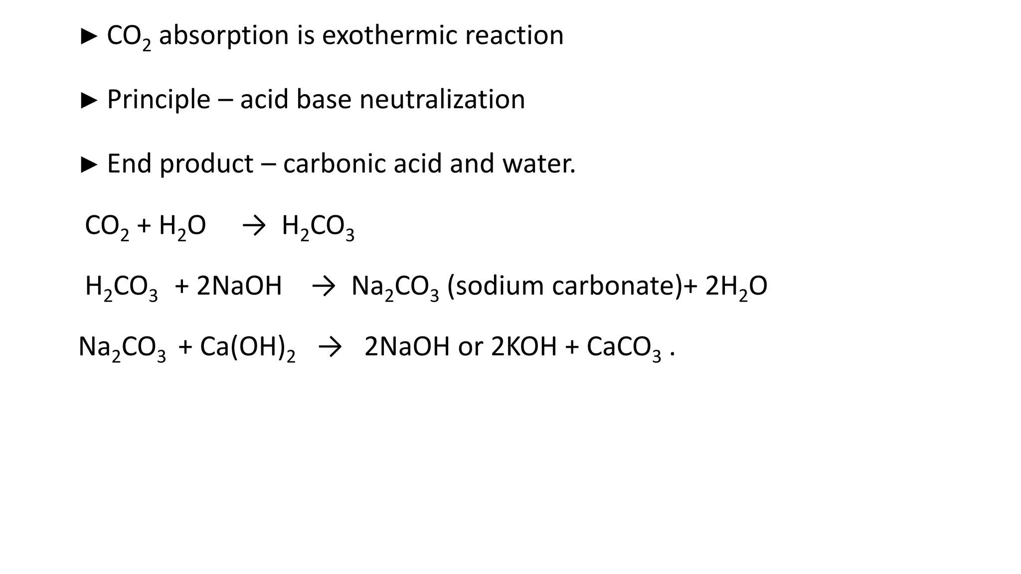
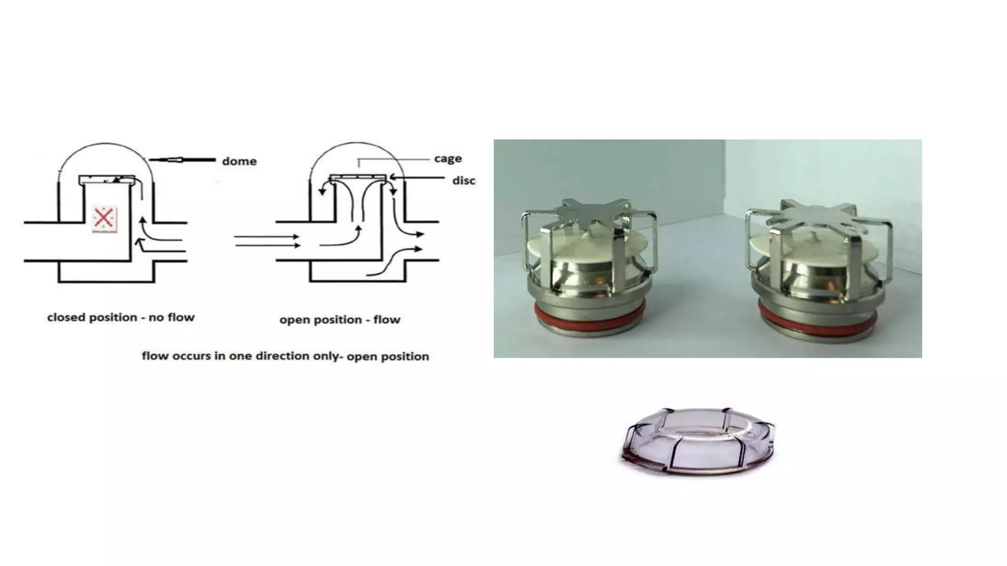
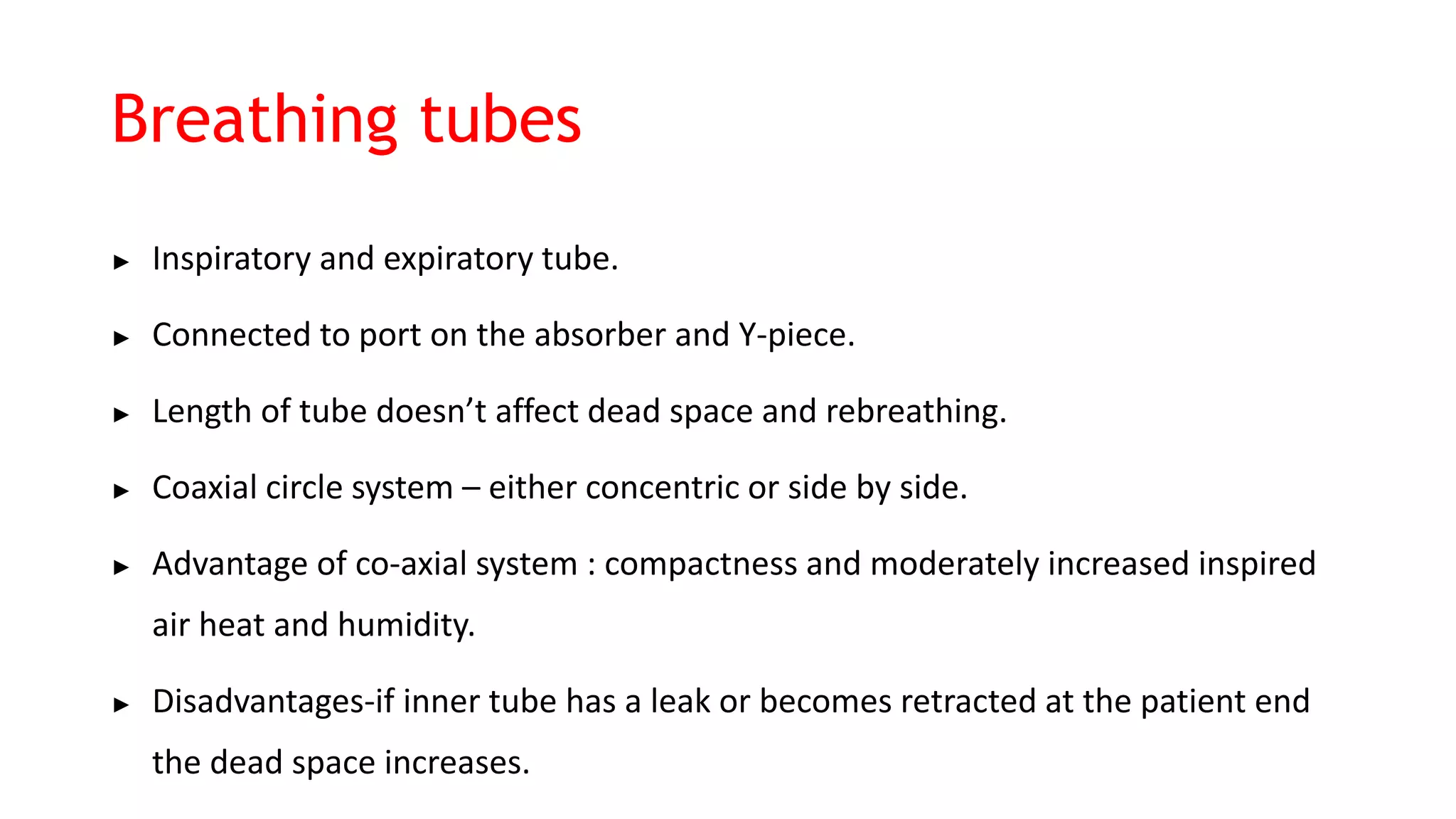
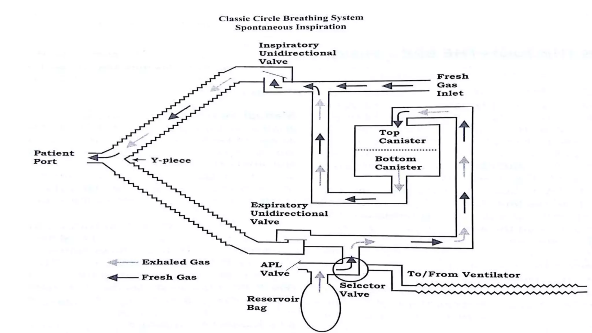
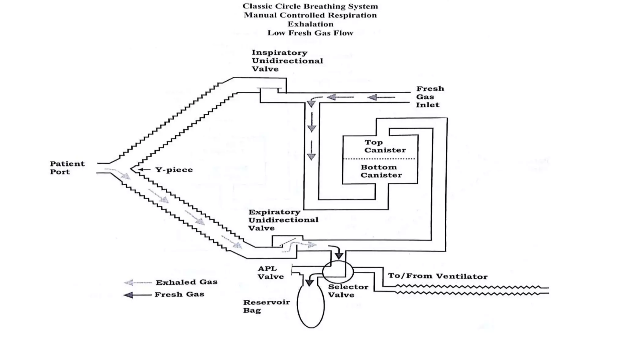
CIRCLE SYSTEM
MODERATOR :
DR. CHANDRASHEKAR DANDI
PRESENTER:
DR. PRAVEENSHARATH
BREATHING SYSTEM
A breathing system is an assembly of components, which delivers gases from the
anaesthesia machine to patients airway. It starts from the point of fresh gas inlet to
the point where gas escapes to the atmosphere or a scavenging system.
► Scavenging system is not included in the breathing system.
► Allows continuous flow from anaesthesia machine to be converted to
intermittent flow.
► Provides functions like gas sampling, airway pressure , flow and volume
monitoring.
► Circle system is so named, as gas flow in circular pathway, in one
direction through separate inspiratory and expiratory channels, CO2
exhaled by the patient is removed by absorbent.
► Vital component of circle system is CO2 absorber.
COMPONENTS OF CIRCLE SYSTEM :
► CO2 absorber
► Unidirectional valves
► Inspiratory and expiratory ports
► Fresh gas inlet
► Y- piece
► APL valve
► Pressure gauge
► Breathing tubes
► Reservoir bag
► Bag and ventilator selector switch
Absorber assembly :
An absorber assembly consists of
► A canister containing an absorbent.
► two ports for connection to breathing tubes
► a fresh gas inlet.
► Other components that may be mounted are inspiratory and
expiratory unidirectional valves , an adjustable pressure limiting
(APL) valve, and a bag mount.
Absorber assembly
Canisters :
The absorbent is held in canisters.
► Single or two canisters in series can be used.
► Side walls are transparent so that color changes can be easily
recognised.
► Comes in large and small sizes.
Canisters
Absorbent
Types
► High alkali absorbents
High amount of NaOH or KOH
When desiccated react with anesthetic agent to form CO or
compound-A
Do not change color when dry.
► Low alkali absorbents
Less amount of KOH or NaOH
Less amount of CO or compound-A when desiccated.
► Alkali free absorbent
Consists mainly Ca(OH)2 and other added agents
No evidence of CO formation
Little or no compound-A formation
Different formulations
► 1. Sodalime
2. Baralyme
3. Sofnolime
4. Amsorb plus
5. Ca(OH)2 lime etc,.
6. LiOH lime
► Sodalime is made of
► Ca(OH)2 - 80%
► NaOH – 4%
► KOH – 1%
► Water – 14% to 19 %
Silica or Kieselguhr – helps in hardening and reduced dust formation.
Indicator
► CO2 absorption is exothermic reaction
► Principle – acid base neutralization
► End product – carbonic acid and water.
CO2 + H2O → H2CO3
H2CO3 + 2NaOH → Na2CO3 (sodium carbonate)+ 2H2O
Na2CO3 + Ca(OH)2 → 2NaOH or 2KOH + CaCO3 .
Pattern of CO2 absorption
A. Unused absorbent in the canister.
B. After limited use- absorption of CO2 has occurred primarily at the inlet and to lesser extent along the sides.
C. After extensive use – granules at the inlet and along the sides are exhausted.
D. Exhausted sodalime – few granules at the distal 1/3rd are still capable of absorbing CO2.
E. Channeling effect
Indicators
color When fresh when exhausted
Phenolphthalein white Pink
Ethyl violet White Purple
Clayton yellow Red Yellow
Ethyl orange Orange Yellow
Mimosa Z Red White
► Shape and size of absorbent
pellets or granules form
Advantage - small granules increases the surface area, decreases the
gas channelling along low resistance pathway.
Disadvantage –
increased resistance ,
caking.
4 to 8 mesh more commonly used.
REACTIONS BETWEEN ABSORBENTS AND
ANESTHETIC AGENTS
► Haloalkene Formation
Halothane degradation most often occurs during closed-circuit anesthesia and
produces the haloalkene 2-bromo-2- chloro-1, 1-difluoroethene
(BCDFE).Nephrotoxic in rats.
►Compound A Formation
Sevoflurane decomposes in the presence of carbon dioxide absorbents to
compound A. Compound A is vinyl ether and has dose dependent
nephrotoxic effects in rats.
Carbon monoxide formation
► when desflurane, enflurane, or isoflurane is passed through
desiccated absorbent containing a strong alkali (potassium or
sodium hydroxide)
► When sevoflurane is degraded by desiccated absorbent, carbon
monoxide is formed if the temperature exceeds 80°C.
Factors associated with carbon monoxide
formation:
► Absorbent Composition – NaOH , KOH
► Absorbent Desiccation ( dehydrated absorbent).
► Anesthetic Agent – Desflurane > Enflurane> Isoflurane
Halothane produces very less amount of CO.
► Increased temperature Inside the Absorber.
► Fresh Gas Flow - FGF leads to more dessication of absorbent and more CO production.
► Carbon Dioxide Absorption – Increases absorption leads to decreased CO production.
The APSF recommendations to prevent
absorbent desiccation if the department
continues to use strong alkali absorbents
with volatile anesthetic agents:
► All gas flows should be turned OFF after each case.
► Vaporizers should be turned OFF when not in use.
► Canisters on an anesthesia machine that is commonly not used for a
long period of time should not be filled with absorbent that contains
strong alkali or should be filled with fresh absorbent before each use.
► The absorbent should be changed routinely, at least once a week,
preferably on a Monday morning, and whenever fresh gas has been
flowing for an extensive or indeterminate period of time.
The canister should be labelled with the filling date.
Checking this date should be part of the daily machine checklist.
If a double-chamber absorber is used, the absorbent in both canisters
should be changed at the same time.
► The practice of supplying oxygen for administration to a patient who is not
receiving general anesthesia through the circle system should be strongly
discouraged.
► Using fresh gas to dry breathing system components should be
discouraged.
WHEN AND HOW TO CHANGE THE ABSORBENT
► Inspired Carbon Dioxide - Most reliable method ( indicated by capnograph)
► Indicator Color Change
► Heat in the Canister
Unidirectional valves
► Two unidirectional (flutter, one way, check, directional, dome, flap,
nonreturn, inspiratory, and expiratory) valves .
► Ensure that gases flow toward the patient in one breathing tube and away
in the other.
► They are usually part of the absorber assembly.
► Can be horizontal or vertical.
Y - PIECE
► Y - piece is a three-way tubular connector with two 22-mm male ports for
connection to the breathing tubes.
► a 15-mm female patient connector for a tracheal tube or supraglottic airway
device.
► The patient connection port usually has a coaxial 22-mm male fitting to allow
direct connection between the Y-piece and a face mask.
► A septum may be placed in the Y-piece to decrease the dead space.
Y - PIECE
Adjustable pressure - limiting valve
► During spontaneous breathing, the valve is left fully open and gas flows
through the valve during exhalation.
► When manually assisted or controlled ventilation is used, the APL valve
should be closed enough that the desired inspiratory pressure can be
achieved.
► When this pressure is reached, the valve opens and excess gas is vented to
the scavenging system during inspiration.
Pressure guage
► An analog pressure gauge (manometer) attached to the exhalation
pathway.
► The gauge is usually the diaphragm type.
► Changes in pressure in the breathing system are transmitted to the
space between two diaphragms, causing them to move inward or
outward.
► Marked in terms of kpa or CmH2O.
► On newer machines- virtual pressure guage.
Breathing tubes
► Inspiratory and expiratory tube.
► Connected to port on the absorber and Y-piece.
► Length of tube doesn’t affect dead space and rebreathing.
► Coaxial circle system – either concentric or side by side.
► Advantage of co-axial system : compactness and moderately increased inspired
air heat and humidity.
► Disadvantages-if inner tube has a leak or becomes retracted at the patient end
the dead space increases.
Reservoir bag
∙ Permits manual ventilation, manual assessment of compliance.
∙ Volume buffer.
∙ The bag is usually attached to a 22-mm male bag port (bag mount or
extension).
∙ Indicator of adequacy of fresh gas, over leak.
∙ Sizes from 500 mL-3 L.
∙ Small bags on 15 mm circle circuits provide excellent feel of the lung
when hand-ventilating neonates.
∙ Can hold 10 × nominal volume before bursting.
∙ Pressure rises to peak of about 50-70 cmH2O but falls late with
massive distension
ARRANGEMENT OF COMPONENTS
Objectives
► Minimizing absorbent desiccation.
► Maximum inclusion of fresh gas in the inspired mixture and
maximum venting of alveolar gases.
► Minimal consumption of absorbent.
► Accurate readings from a respirometer placed in system.
► Maximal humidification of inspired gases.
► Minimal dead space.
► Low resistance.
► Minimal pull on the tracheal tube, mask or supraglottic device.
► Convenience.
Arrangement of fresh gas inlet
FGF-1 Fresh gas inlet placed between absorber and inspiratory
unidirectional valve.
► Advantage – its close to the patient and maximum fresh gas
enters patient’s lungs.
► Disadvantage – during exhalation or exhalation pause , fresh gas can
flow retrograde into the absorber and causing desiccation at the
outlet.
FGF – 2
FG inlet just upstream of absorber
• Improved humidification • More venting of fresh gas through
APL.
• More absorbent desiccation.
• Dust blow during oxygen flush usage.
FGF-3
Downstream of inspiratory unidirectional
valve.
• Change in FG composition reflected
more rapidly in inspired gases.
• No retrograde flow through absorbent
when machine is not in use.
• During exhalation FG joins exhaled
gases and escape through APL
without reaching the patient.
• Respirometer placed on the
exhalation side of circuit will not
record the volume accurately unless
the FGF is turned off.
FGF- 4
Placing a FG inlet upstream of the bag
and APL valve
• All disadvantages of position 2
• More venting of FG and dilution of
exhaled gas before it is vented.
FGF-5
Placing FG inlet upstream of expiratory
unidirectional valve.
• During inspiration FGF will force
exhaled gases that contain CO2 back
towards patient.
• All disadvantage of position 4
Adjustable pressure-limiting valve
Position Advantage Disadvantage
APL-1
Near reservoir bag downstream of
expiratory unidirectional valve.
Fresh gas will be vented only if the flow is
high.
APL-2
On Y- Piece
Most efficient use occurs in case of
spontaneous ventilation. Because
overflow occurs during later part of
exhalation causing venting of gas
containing high CO2.
• Overflow occurs during inspiration in
case of controlled ventilation causing
venting of FG and gas that has passed
through absorber.
• Added weight increase the chances of
disconnections.
• Valve will be difficult to adjust during
head and neck surgeries.
• Decrease in inspired air humidity and
heat.
APL -3
Upstream of expiratory unidirectional
valve.
Inefficient absorbent use because all
gases in the RB has to pass through
canister.
APL-4
Between inspiratory unidirectional valve
and patient
Exhaled gases will move retrograde in the
inspiratory tube causing increase in dead
space.
APL-5
Between fresh gas inlet and inspiratory
unidirectional valve.
Fresh gas will be vented.
GAS FLOW THROUGH THE BREATHING SYSTEM
In classic circle system ventilator is in
proximity
to the reservoir bag.
Classic circle system has been used for
Ohmeda
Classic circle breathing system- flow during
spontaneous exhalation
Classic circle breathing system- flow during
manual ventilation (inspiration)
ADVANTAGES OF CIRCLE SYSTEM
► Cost reduction (use less agent and O2).
► Increased tracheal warmth and humidity .
► Decreased exposure of OT personnel to waste gases
► Decreased pollution of the environment.
DISADVANTAGES OF CIRCLE SYSTEM
► Greater size, less portability
► Increased complexity
► Higher risk of disconnection or malfunction
► Increased resistance (of valves during spontaneous ventilation).
► Difficult prediction of inspired gas concentration during low fresh
gas flow
REFERENCES
• AIRWAY MANAGEMENT, 5TH EDITION , RASHID M KHAN
• BAHETI ANESTHETIC EQUIPMENT AND PROCEDURES 3RD EDITION
THANK YOU

CIRCLE SYSTEM.pptx

  • 1.
    CIRCLE SYSTEM MODERATOR : DR.CHANDRASHEKAR DANDI PRESENTER: DR. PRAVEENSHARATH
  • 2.
    BREATHING SYSTEM A breathingsystem is an assembly of components, which delivers gases from the anaesthesia machine to patients airway. It starts from the point of fresh gas inlet to the point where gas escapes to the atmosphere or a scavenging system. ► Scavenging system is not included in the breathing system. ► Allows continuous flow from anaesthesia machine to be converted to intermittent flow. ► Provides functions like gas sampling, airway pressure , flow and volume monitoring.
  • 3.
    ► Circle systemis so named, as gas flow in circular pathway, in one direction through separate inspiratory and expiratory channels, CO2 exhaled by the patient is removed by absorbent. ► Vital component of circle system is CO2 absorber.
  • 4.
    COMPONENTS OF CIRCLESYSTEM : ► CO2 absorber ► Unidirectional valves ► Inspiratory and expiratory ports ► Fresh gas inlet ► Y- piece ► APL valve ► Pressure gauge ► Breathing tubes ► Reservoir bag ► Bag and ventilator selector switch
  • 5.
    Absorber assembly : Anabsorber assembly consists of ► A canister containing an absorbent. ► two ports for connection to breathing tubes ► a fresh gas inlet. ► Other components that may be mounted are inspiratory and expiratory unidirectional valves , an adjustable pressure limiting (APL) valve, and a bag mount.
  • 6.
  • 7.
    Canisters : The absorbentis held in canisters. ► Single or two canisters in series can be used. ► Side walls are transparent so that color changes can be easily recognised. ► Comes in large and small sizes.
  • 8.
  • 9.
    Absorbent Types ► High alkaliabsorbents High amount of NaOH or KOH When desiccated react with anesthetic agent to form CO or compound-A Do not change color when dry.
  • 10.
    ► Low alkaliabsorbents Less amount of KOH or NaOH Less amount of CO or compound-A when desiccated. ► Alkali free absorbent Consists mainly Ca(OH)2 and other added agents No evidence of CO formation Little or no compound-A formation
  • 11.
    Different formulations ► 1.Sodalime 2. Baralyme 3. Sofnolime 4. Amsorb plus 5. Ca(OH)2 lime etc,. 6. LiOH lime
  • 12.
    ► Sodalime ismade of ► Ca(OH)2 - 80% ► NaOH – 4% ► KOH – 1% ► Water – 14% to 19 % Silica or Kieselguhr – helps in hardening and reduced dust formation. Indicator
  • 14.
    ► CO2 absorptionis exothermic reaction ► Principle – acid base neutralization ► End product – carbonic acid and water. CO2 + H2O → H2CO3 H2CO3 + 2NaOH → Na2CO3 (sodium carbonate)+ 2H2O Na2CO3 + Ca(OH)2 → 2NaOH or 2KOH + CaCO3 .
  • 15.
    Pattern of CO2absorption A. Unused absorbent in the canister. B. After limited use- absorption of CO2 has occurred primarily at the inlet and to lesser extent along the sides. C. After extensive use – granules at the inlet and along the sides are exhausted. D. Exhausted sodalime – few granules at the distal 1/3rd are still capable of absorbing CO2. E. Channeling effect
  • 16.
    Indicators color When freshwhen exhausted Phenolphthalein white Pink Ethyl violet White Purple Clayton yellow Red Yellow Ethyl orange Orange Yellow Mimosa Z Red White
  • 17.
    ► Shape andsize of absorbent pellets or granules form Advantage - small granules increases the surface area, decreases the gas channelling along low resistance pathway. Disadvantage – increased resistance , caking. 4 to 8 mesh more commonly used.
  • 18.
    REACTIONS BETWEEN ABSORBENTSAND ANESTHETIC AGENTS ► Haloalkene Formation Halothane degradation most often occurs during closed-circuit anesthesia and produces the haloalkene 2-bromo-2- chloro-1, 1-difluoroethene (BCDFE).Nephrotoxic in rats. ►Compound A Formation Sevoflurane decomposes in the presence of carbon dioxide absorbents to compound A. Compound A is vinyl ether and has dose dependent nephrotoxic effects in rats.
  • 19.
    Carbon monoxide formation ►when desflurane, enflurane, or isoflurane is passed through desiccated absorbent containing a strong alkali (potassium or sodium hydroxide) ► When sevoflurane is degraded by desiccated absorbent, carbon monoxide is formed if the temperature exceeds 80°C.
  • 20.
    Factors associated withcarbon monoxide formation: ► Absorbent Composition – NaOH , KOH ► Absorbent Desiccation ( dehydrated absorbent). ► Anesthetic Agent – Desflurane > Enflurane> Isoflurane Halothane produces very less amount of CO. ► Increased temperature Inside the Absorber. ► Fresh Gas Flow - FGF leads to more dessication of absorbent and more CO production. ► Carbon Dioxide Absorption – Increases absorption leads to decreased CO production.
  • 21.
    The APSF recommendationsto prevent absorbent desiccation if the department continues to use strong alkali absorbents with volatile anesthetic agents: ► All gas flows should be turned OFF after each case. ► Vaporizers should be turned OFF when not in use. ► Canisters on an anesthesia machine that is commonly not used for a long period of time should not be filled with absorbent that contains strong alkali or should be filled with fresh absorbent before each use.
  • 22.
    ► The absorbentshould be changed routinely, at least once a week, preferably on a Monday morning, and whenever fresh gas has been flowing for an extensive or indeterminate period of time. The canister should be labelled with the filling date. Checking this date should be part of the daily machine checklist. If a double-chamber absorber is used, the absorbent in both canisters should be changed at the same time.
  • 23.
    ► The practiceof supplying oxygen for administration to a patient who is not receiving general anesthesia through the circle system should be strongly discouraged. ► Using fresh gas to dry breathing system components should be discouraged.
  • 24.
    WHEN AND HOWTO CHANGE THE ABSORBENT ► Inspired Carbon Dioxide - Most reliable method ( indicated by capnograph) ► Indicator Color Change ► Heat in the Canister
  • 25.
    Unidirectional valves ► Twounidirectional (flutter, one way, check, directional, dome, flap, nonreturn, inspiratory, and expiratory) valves . ► Ensure that gases flow toward the patient in one breathing tube and away in the other. ► They are usually part of the absorber assembly. ► Can be horizontal or vertical.
  • 27.
    Y - PIECE ►Y - piece is a three-way tubular connector with two 22-mm male ports for connection to the breathing tubes. ► a 15-mm female patient connector for a tracheal tube or supraglottic airway device. ► The patient connection port usually has a coaxial 22-mm male fitting to allow direct connection between the Y-piece and a face mask. ► A septum may be placed in the Y-piece to decrease the dead space.
  • 28.
  • 29.
    Adjustable pressure -limiting valve ► During spontaneous breathing, the valve is left fully open and gas flows through the valve during exhalation. ► When manually assisted or controlled ventilation is used, the APL valve should be closed enough that the desired inspiratory pressure can be achieved. ► When this pressure is reached, the valve opens and excess gas is vented to the scavenging system during inspiration.
  • 30.
    Pressure guage ► Ananalog pressure gauge (manometer) attached to the exhalation pathway. ► The gauge is usually the diaphragm type. ► Changes in pressure in the breathing system are transmitted to the space between two diaphragms, causing them to move inward or outward. ► Marked in terms of kpa or CmH2O. ► On newer machines- virtual pressure guage.
  • 31.
    Breathing tubes ► Inspiratoryand expiratory tube. ► Connected to port on the absorber and Y-piece. ► Length of tube doesn’t affect dead space and rebreathing. ► Coaxial circle system – either concentric or side by side. ► Advantage of co-axial system : compactness and moderately increased inspired air heat and humidity. ► Disadvantages-if inner tube has a leak or becomes retracted at the patient end the dead space increases.
  • 32.
    Reservoir bag ∙ Permitsmanual ventilation, manual assessment of compliance. ∙ Volume buffer. ∙ The bag is usually attached to a 22-mm male bag port (bag mount or extension). ∙ Indicator of adequacy of fresh gas, over leak. ∙ Sizes from 500 mL-3 L. ∙ Small bags on 15 mm circle circuits provide excellent feel of the lung when hand-ventilating neonates. ∙ Can hold 10 × nominal volume before bursting. ∙ Pressure rises to peak of about 50-70 cmH2O but falls late with massive distension
  • 33.
    ARRANGEMENT OF COMPONENTS Objectives ►Minimizing absorbent desiccation. ► Maximum inclusion of fresh gas in the inspired mixture and maximum venting of alveolar gases. ► Minimal consumption of absorbent. ► Accurate readings from a respirometer placed in system.
  • 34.
    ► Maximal humidificationof inspired gases. ► Minimal dead space. ► Low resistance. ► Minimal pull on the tracheal tube, mask or supraglottic device. ► Convenience.
  • 35.
  • 36.
    FGF-1 Fresh gasinlet placed between absorber and inspiratory unidirectional valve. ► Advantage – its close to the patient and maximum fresh gas enters patient’s lungs. ► Disadvantage – during exhalation or exhalation pause , fresh gas can flow retrograde into the absorber and causing desiccation at the outlet.
  • 37.
    FGF – 2 FGinlet just upstream of absorber • Improved humidification • More venting of fresh gas through APL. • More absorbent desiccation. • Dust blow during oxygen flush usage. FGF-3 Downstream of inspiratory unidirectional valve. • Change in FG composition reflected more rapidly in inspired gases. • No retrograde flow through absorbent when machine is not in use. • During exhalation FG joins exhaled gases and escape through APL without reaching the patient. • Respirometer placed on the exhalation side of circuit will not record the volume accurately unless the FGF is turned off. FGF- 4 Placing a FG inlet upstream of the bag and APL valve • All disadvantages of position 2 • More venting of FG and dilution of exhaled gas before it is vented. FGF-5 Placing FG inlet upstream of expiratory unidirectional valve. • During inspiration FGF will force exhaled gases that contain CO2 back towards patient. • All disadvantage of position 4
  • 38.
  • 39.
    Position Advantage Disadvantage APL-1 Nearreservoir bag downstream of expiratory unidirectional valve. Fresh gas will be vented only if the flow is high. APL-2 On Y- Piece Most efficient use occurs in case of spontaneous ventilation. Because overflow occurs during later part of exhalation causing venting of gas containing high CO2. • Overflow occurs during inspiration in case of controlled ventilation causing venting of FG and gas that has passed through absorber. • Added weight increase the chances of disconnections. • Valve will be difficult to adjust during head and neck surgeries. • Decrease in inspired air humidity and heat. APL -3 Upstream of expiratory unidirectional valve. Inefficient absorbent use because all gases in the RB has to pass through canister. APL-4 Between inspiratory unidirectional valve and patient Exhaled gases will move retrograde in the inspiratory tube causing increase in dead space. APL-5 Between fresh gas inlet and inspiratory unidirectional valve. Fresh gas will be vented.
  • 40.
    GAS FLOW THROUGHTHE BREATHING SYSTEM In classic circle system ventilator is in proximity to the reservoir bag. Classic circle system has been used for Ohmeda
  • 42.
    Classic circle breathingsystem- flow during spontaneous exhalation
  • 43.
    Classic circle breathingsystem- flow during manual ventilation (inspiration)
  • 45.
    ADVANTAGES OF CIRCLESYSTEM ► Cost reduction (use less agent and O2). ► Increased tracheal warmth and humidity . ► Decreased exposure of OT personnel to waste gases ► Decreased pollution of the environment.
  • 46.
    DISADVANTAGES OF CIRCLESYSTEM ► Greater size, less portability ► Increased complexity ► Higher risk of disconnection or malfunction ► Increased resistance (of valves during spontaneous ventilation). ► Difficult prediction of inspired gas concentration during low fresh gas flow
  • 47.
    REFERENCES • AIRWAY MANAGEMENT,5TH EDITION , RASHID M KHAN • BAHETI ANESTHETIC EQUIPMENT AND PROCEDURES 3RD EDITION
  • 48.