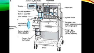
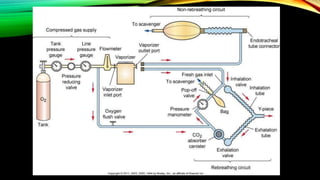
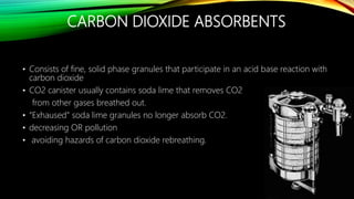
ANESTHESIA
MACHINE
Provide a reliable mechanism to
continually ventilate the anesthesized
patient
Serve as a source for supplemental
oxygen
Provide a mechanism for the delivery of
volatile anesthetic agents
Serve as a monitor and early warning
system for several potential hazards
encountered
FOUR GOALS
• The American National Standards Institute and subsequently the
ASTM (formerly the American Society for Testing and
Materials) published standard specifications for
anesthesia machines and their components.
SUPPLY AND COMPRESSED GASES
CYLINDER CYLINDER BANK LIQUID OXYGEN
DELIVERY SYSTEM TO ANESTHESIA MACHINE
PIPELINE SYSTEM
- primary source of gas supply for the anesthesia machine
- Oxygen, nitrous oxides, and often air are delivered
- The tubing is color coded and connects to the pipeline inlet of the machine
through a noninterchangeable diameter-index safety system (DISS) fitting
that prevents incorrect hose attachment
- The check valve is located down stream from the pipeline inlet, prevents
reverse flow of gases
DELIVERY SYSTEM TO ANESTHESIA MACHINE
CYLINDER SYSTEM
-Gas is compressed in a metal cylinder and held under pressure
-Available in various sizes
“E” holds 660 L of oxygen and is attached to the anesthesia machine
“H” cylinders hold 6900 L of oxygen and stand separate from the
machine
- Tanks are color coded for safety and recognition
Oxygen tanks: GREEN (U.S.), white (Canada)
Nitrous oxide tanks: blue (U.S.)
Carbon dioxide tanks: gray (U.S.)
- Presence of tank pressure guage - Display of the pressure of oxygen in the
tank
E SIZE COMPRESSED GAS CYLINDERS
DELIVERY OF GASES
Consists of those parts which receive gas at
cylinder pressure
- Hanger Yolk (reserve gas cylinder holder)
- Check valve (prevent reverse flow of gas)
- Cylinder Pressure Indicator (Gauge)
- Pressure Reducing Device (Regulator)
DELIVERY OF GASES
Receives gasses from the regulator
or the hospital pipeline at pressures
of 40-55 psig
Consists of:
- pipeline inlets and pressure
gauges
- ventilator power inlet
- oxygen pressure-failure device
(fail-safe) and alarm
- oxygen and nitrous oxide second-
stage regulators
- oxygen flush valve (35 – 70 L/min)
DELIVERY OF GASES
Extends from the flow
control valves to the
common gas outlet
Consists of:
- Flow meters
- Vaporizer mounting device
- Check valve
- Common gas outlet
HANGER YOLK
• orients and supports the cylinder, providing a gas-tight seal and ensuring a
unidirectional gas flow into the machine
• Index pins: Pin Index Safety System
CYLINDER PRESSURE INDICATOR
• Display of the pressure of oxygen in the tank.
• Reads zero when it is empty, when tank is turned off, and all gas has been
removed from the machine
• Actual amount in tank is displayed when the tank is turned on
PRESSURE REDUCING DEVICE
• Regulates the pressure of the gas leaving the tank and going into the anesthesia
machine
• Allows a constant flow of gas into the machine, despite pressure changes within
the tank
• Reduces the pressure of oxygen that leaves the tank at 2200 psi to a safer 50 psi.
OXYGEN PRESSURE FAILURE DEVICE
AND ALARM
• Designed so that whenever the oxygen supply pressure is reduced below normal,
the oxygen concentration at the common gas outlet does not fall below 19%
• A Fail-Safe valve is present in the gas line supplying each of the flowmeters except
O2. This valve is controlled by the O2 supply pressure and shuts off or
proportionately decreases the supply pressure of all other gasses as the O2 supply
pressure decreases
• The machine standard specifies that whenever the oxygen supply pressure falls
below a manufacturer-specified threshold (usually 30 psig) a medium priority alarm
shall blow within 5 seconds.
• there are 2 kinds of fail-safe valves:
• Pressure sensor shut-off valve (Ohmeda) - If the oxygen supply pressure falls
below the threshold value the valve closes and the gas in that limb (e.g.. N2O), does
not advance to its flow-control valve.
• Oxygen failure protection device (Drager) - The pressure of all gases controlled
the OFPD will decrease proportionately with the oxygen pressure
SECOND STAGE REDUCING DEVICE
• Located just upstream of the flow control valves
• Receives gas from the pipeline inlet or the cylinder reducing device and reduces it
further to 26 psig for N2O and 12-16 psig for O2
• Purpose is to eliminate fluctuations in pressure supplied to the flow indicators
caused by fluctuations in pipeline pressure
OXYGEN FLUSH VALVE
• Permits the application of oxygen flow from the in-line working pressure of
55 psi through the common gas outlet to the patient
• Flow rates of oxygen through this alternative pathway that bypasses the
flowmeters can range from 35 to 75 L/min
• Presence of one way check valve
FLOWMETER
• Components
• Control knob
• Needle valve
• Funnel shaped glass tube
• Aluminum bobbin indicator (float)
• Specifically calibrated for each gas
• Flow read at top of bobbin in L/min
• When the flow control valve is opened the gas enters at
the bottom and flows up the tube elevating the indicator
• The indicator floats freely at a point where the downward
force on it (gravity) equals the upward force caused by gas molecules hitting the bottom of
the float
ARRANGEMENT OF THE FLOW-INDICATOR TUBES
• In the presence of a flowmeter leak, a hypoxic mixture is less likely to occur if the O2
flowmeter is downstream of all other flowmeters
• In A and B a hypoxic mixture can result because a substantial portion of oxygen flow
passes through the leak, and all nitrous oxide is directed to the common gas outlet
• * Note that a leak in the oxygen flowmeter tube can cause a hypoxic mixture, even
when oxygen is located in the downstream position
VAPORIZERS
• A vaporizer is an instrument designed to change a liquid anesthetic agent into its
vapor and add a controlled amount of this vapor to the fresh gas flow
• Adds accurate concentrations of volatile anaesthetic agent to gas mixture
• Agent specific and calibrated according to vapour pressure
Variable bypass
• Fresh gas flow from the flowmeters enters
the inlet of the vaporizer when turned on.
• The concentration control dial setting splits
this stream into bypass gas (which does not
enter the vaporizing chamber), and carrier
gas (also called chamber flow, which flows
over the liquid agent).
ANESTHESIA BREATHING SYSTEM:
CIRCLE SYSTEM
- The system that brings the fresh gas from the
vaporizer to the patient and takes the expired
gases from the patient
- May contain unidirectional valves, reservoir
bag, pop off valve, CO2 canister, O2 flush,
negative pressure relief valve, pressure
manometer.
ANESTHESIA BREATHING SYSTEM:
CIRCLE SYSTEM
• Most commonly used design
• Arrangement is variable, but to prevent re-breathing of CO2, the following rules
must be followed:
- Unidirectional valves between the patient and the reservoir bag
-Fresh-gas-flow cannot enter the circuit between the expiratory valve and
the patient
-Adjustable pressure-limiting valve (APL) cannot be located between the
patient and the inspiratory valve
Advantages:
• Relative stability of inspired concentration
• Conservation of respiratory moisture and heat
• Prevention of operating room pollution
• PaCO2 depends only on ventilation, not fresh gas flow
• Low fresh gas flows can be used
Disadvantages:
• Complex design = potential for malfunction
• High resistance (multiple one-way valves) = higher work of breathing
UNIDIRECTIONAL VALVES
• One-way valves that allow the flow of fresh gas to enter the inhalation valve and exit
the exhalation valve.
• Valve is either a rigid disk or a flap that flutters as gas flows past it
• Inhalation valve opens as patient inhales, anesthetic enters the hose, then the
endotracheal tube and the patient
• CO2 and anesthetic gases are then exhaled, travel down the hose and through the
unidirectional exhalation valve. This valve prevents the expired gases from traveling
back to the patient before the CO2 is removed
NON REBREATHING SYSTEM
Advantages
• Simply, light weight, easy to positioning
• Remote anesthesia
• Low resistance
Disadvantages
• Require high FGF, more pollution
• loss more heat and water from airway
• Carbon dioxide retention
IMPACT OF FRESH GAS FLOW
HIGH FLOW: risk of trauma to the lung
Emergence
Low Flow: rebreathing bag collapse, patient will be unable to breath
harmful metabolite and will accumulate
ADJUSTABLE PRESSURE LIMITING VALVE
• Adjustable valve that releases gases to the scavenging system and is intended to
provide control of the pressure in the breathing system
• Bag-mask Ventilation: Valve is usually left partially open. During inspiration the
bag is squeezed pushing gas into the inspiratory limb until the pressure relief is
reached, opening the APL valve.
• Mechanical Ventilation: The APL valve is excluded from the circuit when the
selector switch is changed from manual to automatic ventilation
BREATHING BAG
• Fills as gases enter the circuit or patient exhales, deflates as patient inhales
• Stores gas
• Helps in determining correct endotracheal tube placement. Movement of bag
with breaths = tube in trachea
• Allows assessment of respiratory rate and depth
• Allows “bagging” of the patient
• - reverse atelectasis if present
• -removal of CO2 and anesthetic that builds up when respirations have
decreased in volume
CARBON DIOXIDE ABSORBENTS
• Consists of fine, solid phase granules that participate in an acid base reaction with
carbon dioxide
• CO2 canister usually contains soda lime that removes CO2
from other gases breathed out.
• “Exhaused” soda lime granules no longer absorb CO2.
• decreasing OR pollution
• avoiding hazards of carbon dioxide rebreathing.
HOW DO I KNOW WHEN THE GRANULES ARE EXHAUSTED?
• Color change to violet, off-white or pink depending on the brand. Based on pH.
• CO2 saturated granules are hard and brittle, new ones can be chipped and
crumbled
• Once color becomes abnormal, it is possible that it changes back to normal within
hours
SCAVENGING SYSTEM
- The primary determinant of the amount of waste gas scavenged is the fresh gas
flow out of the common gas outlet
- Scavenging is the collection and removal of vented anesthetic gases from the OR
- Scavenging may be active (suction applied) or passive (waste gases proceed
passively down corrugated tubing through the exhaust grill of the OR)
- Protects the breathing circuit or ventilator from excessive positive or negative
pressure
ESSENTIAL SAFETY FEATURES ON A
MODERN ANESTHESIA WORKSTATION
Essential Features Purpose
Noninterchangeable gas-specific connections
to pipeline inlets (DISS)1 with pressure
gauges, filter, and check valve
Prevent incorrect pipeline attachments; detect
failure, depletion, or fluctuation
Pin index safety system for cylinders with
pressure gauges, and at least one oxygen
cylinder
Prevent incorrect cylinder attachments;
provide backup gas supply; detect depletion
Low oxygen pressure alarm Detect oxygen supply failure at the common
gas inlet
Essential Features Purpose
Minimum oxygen/nitrous oxide ratio controller
device (hypoxic guard)
Prevent delivery of less than 21% oxygen
Oxygen failure safety device (shut-off or
proportioning device)
Prevent administration of nitrous oxide or
other gases when the oxygen supply fails
Oxygen must enter the common manifold
downstream to other gases
Prevent hypoxia in event of proximal gas leak
Oxygen concentration monitor and alarm Prevent administration of hypoxic gas
mixtures in event of a low-pressure system
leak; precisely regulate oxygen concentration
Automatically enabled essential alarms and
monitors (eg, oxygen concentration)
Prevent use of the machine without essential
monitors
Essential Features
Purpose
Vaporizer interlock device Prevent simultaneous administration of more
than one volatile agent
Capnography and anesthetic gas
measurement
Guide ventilation; prevent anesthetic
overdose; help reduce awareness
Oxygen flush mechanism that does not pass
through vaporizers
Rapidly refill or flush the breathing circuit
Breathing circuit pressure monitor and alarm Prevent pulmonary barotrauma and detect
sustained positive, high peak, and negative
airway pressures
Exhaled volume monitor Assess ventilation and prevent hypo- or
hyperventilation
Essential Features Purpose
Pulse oximetry, blood pressure, and ECG
monitoring
Provide minimal standard monitoring
Mechanical ventilator Control alveolar ventilation more accurately
and during muscle paralysis for prolonged
periods
Backup battery Provide temporary electrical power (> 30
min) to monitors and alarms in event of
power failure
Scavenger system Prevent contamination of the operating room
with waste anesthetic gases

Anesthesia Machine -.pptx

  • 1.
  • 2.
    Provide a reliablemechanism to continually ventilate the anesthesized patient Serve as a source for supplemental oxygen Provide a mechanism for the delivery of volatile anesthetic agents Serve as a monitor and early warning system for several potential hazards encountered FOUR GOALS
  • 3.
    • The AmericanNational Standards Institute and subsequently the ASTM (formerly the American Society for Testing and Materials) published standard specifications for anesthesia machines and their components.
  • 7.
    SUPPLY AND COMPRESSEDGASES CYLINDER CYLINDER BANK LIQUID OXYGEN
  • 8.
    DELIVERY SYSTEM TOANESTHESIA MACHINE PIPELINE SYSTEM - primary source of gas supply for the anesthesia machine - Oxygen, nitrous oxides, and often air are delivered - The tubing is color coded and connects to the pipeline inlet of the machine through a noninterchangeable diameter-index safety system (DISS) fitting that prevents incorrect hose attachment - The check valve is located down stream from the pipeline inlet, prevents reverse flow of gases
  • 9.
    DELIVERY SYSTEM TOANESTHESIA MACHINE CYLINDER SYSTEM -Gas is compressed in a metal cylinder and held under pressure -Available in various sizes “E” holds 660 L of oxygen and is attached to the anesthesia machine “H” cylinders hold 6900 L of oxygen and stand separate from the machine
  • 10.
    - Tanks arecolor coded for safety and recognition Oxygen tanks: GREEN (U.S.), white (Canada) Nitrous oxide tanks: blue (U.S.) Carbon dioxide tanks: gray (U.S.) - Presence of tank pressure guage - Display of the pressure of oxygen in the tank
  • 11.
    E SIZE COMPRESSEDGAS CYLINDERS
  • 12.
    DELIVERY OF GASES Consistsof those parts which receive gas at cylinder pressure - Hanger Yolk (reserve gas cylinder holder) - Check valve (prevent reverse flow of gas) - Cylinder Pressure Indicator (Gauge) - Pressure Reducing Device (Regulator)
  • 13.
    DELIVERY OF GASES Receivesgasses from the regulator or the hospital pipeline at pressures of 40-55 psig Consists of: - pipeline inlets and pressure gauges - ventilator power inlet - oxygen pressure-failure device (fail-safe) and alarm - oxygen and nitrous oxide second- stage regulators - oxygen flush valve (35 – 70 L/min)
  • 14.
    DELIVERY OF GASES Extendsfrom the flow control valves to the common gas outlet Consists of: - Flow meters - Vaporizer mounting device - Check valve - Common gas outlet
  • 15.
    HANGER YOLK • orientsand supports the cylinder, providing a gas-tight seal and ensuring a unidirectional gas flow into the machine • Index pins: Pin Index Safety System
  • 17.
    CYLINDER PRESSURE INDICATOR •Display of the pressure of oxygen in the tank. • Reads zero when it is empty, when tank is turned off, and all gas has been removed from the machine • Actual amount in tank is displayed when the tank is turned on
  • 18.
    PRESSURE REDUCING DEVICE •Regulates the pressure of the gas leaving the tank and going into the anesthesia machine • Allows a constant flow of gas into the machine, despite pressure changes within the tank • Reduces the pressure of oxygen that leaves the tank at 2200 psi to a safer 50 psi.
  • 19.
    OXYGEN PRESSURE FAILUREDEVICE AND ALARM • Designed so that whenever the oxygen supply pressure is reduced below normal, the oxygen concentration at the common gas outlet does not fall below 19% • A Fail-Safe valve is present in the gas line supplying each of the flowmeters except O2. This valve is controlled by the O2 supply pressure and shuts off or proportionately decreases the supply pressure of all other gasses as the O2 supply pressure decreases • The machine standard specifies that whenever the oxygen supply pressure falls below a manufacturer-specified threshold (usually 30 psig) a medium priority alarm shall blow within 5 seconds.
  • 20.
    • there are2 kinds of fail-safe valves: • Pressure sensor shut-off valve (Ohmeda) - If the oxygen supply pressure falls below the threshold value the valve closes and the gas in that limb (e.g.. N2O), does not advance to its flow-control valve. • Oxygen failure protection device (Drager) - The pressure of all gases controlled the OFPD will decrease proportionately with the oxygen pressure
  • 21.
    SECOND STAGE REDUCINGDEVICE • Located just upstream of the flow control valves • Receives gas from the pipeline inlet or the cylinder reducing device and reduces it further to 26 psig for N2O and 12-16 psig for O2 • Purpose is to eliminate fluctuations in pressure supplied to the flow indicators caused by fluctuations in pipeline pressure
  • 22.
    OXYGEN FLUSH VALVE •Permits the application of oxygen flow from the in-line working pressure of 55 psi through the common gas outlet to the patient • Flow rates of oxygen through this alternative pathway that bypasses the flowmeters can range from 35 to 75 L/min • Presence of one way check valve
  • 23.
    FLOWMETER • Components • Controlknob • Needle valve • Funnel shaped glass tube • Aluminum bobbin indicator (float) • Specifically calibrated for each gas • Flow read at top of bobbin in L/min • When the flow control valve is opened the gas enters at the bottom and flows up the tube elevating the indicator • The indicator floats freely at a point where the downward force on it (gravity) equals the upward force caused by gas molecules hitting the bottom of the float
  • 24.
    ARRANGEMENT OF THEFLOW-INDICATOR TUBES • In the presence of a flowmeter leak, a hypoxic mixture is less likely to occur if the O2 flowmeter is downstream of all other flowmeters • In A and B a hypoxic mixture can result because a substantial portion of oxygen flow passes through the leak, and all nitrous oxide is directed to the common gas outlet • * Note that a leak in the oxygen flowmeter tube can cause a hypoxic mixture, even when oxygen is located in the downstream position
  • 25.
    VAPORIZERS • A vaporizeris an instrument designed to change a liquid anesthetic agent into its vapor and add a controlled amount of this vapor to the fresh gas flow • Adds accurate concentrations of volatile anaesthetic agent to gas mixture • Agent specific and calibrated according to vapour pressure
  • 26.
    Variable bypass • Freshgas flow from the flowmeters enters the inlet of the vaporizer when turned on. • The concentration control dial setting splits this stream into bypass gas (which does not enter the vaporizing chamber), and carrier gas (also called chamber flow, which flows over the liquid agent).
  • 27.
    ANESTHESIA BREATHING SYSTEM: CIRCLESYSTEM - The system that brings the fresh gas from the vaporizer to the patient and takes the expired gases from the patient - May contain unidirectional valves, reservoir bag, pop off valve, CO2 canister, O2 flush, negative pressure relief valve, pressure manometer.
  • 28.
    ANESTHESIA BREATHING SYSTEM: CIRCLESYSTEM • Most commonly used design • Arrangement is variable, but to prevent re-breathing of CO2, the following rules must be followed: - Unidirectional valves between the patient and the reservoir bag -Fresh-gas-flow cannot enter the circuit between the expiratory valve and the patient -Adjustable pressure-limiting valve (APL) cannot be located between the patient and the inspiratory valve
  • 29.
    Advantages: • Relative stabilityof inspired concentration • Conservation of respiratory moisture and heat • Prevention of operating room pollution • PaCO2 depends only on ventilation, not fresh gas flow • Low fresh gas flows can be used Disadvantages: • Complex design = potential for malfunction • High resistance (multiple one-way valves) = higher work of breathing
  • 30.
    UNIDIRECTIONAL VALVES • One-wayvalves that allow the flow of fresh gas to enter the inhalation valve and exit the exhalation valve. • Valve is either a rigid disk or a flap that flutters as gas flows past it • Inhalation valve opens as patient inhales, anesthetic enters the hose, then the endotracheal tube and the patient • CO2 and anesthetic gases are then exhaled, travel down the hose and through the unidirectional exhalation valve. This valve prevents the expired gases from traveling back to the patient before the CO2 is removed
  • 31.
    NON REBREATHING SYSTEM Advantages •Simply, light weight, easy to positioning • Remote anesthesia • Low resistance Disadvantages • Require high FGF, more pollution • loss more heat and water from airway • Carbon dioxide retention
  • 32.
    IMPACT OF FRESHGAS FLOW HIGH FLOW: risk of trauma to the lung Emergence Low Flow: rebreathing bag collapse, patient will be unable to breath harmful metabolite and will accumulate
  • 33.
    ADJUSTABLE PRESSURE LIMITINGVALVE • Adjustable valve that releases gases to the scavenging system and is intended to provide control of the pressure in the breathing system • Bag-mask Ventilation: Valve is usually left partially open. During inspiration the bag is squeezed pushing gas into the inspiratory limb until the pressure relief is reached, opening the APL valve. • Mechanical Ventilation: The APL valve is excluded from the circuit when the selector switch is changed from manual to automatic ventilation
  • 34.
    BREATHING BAG • Fillsas gases enter the circuit or patient exhales, deflates as patient inhales • Stores gas • Helps in determining correct endotracheal tube placement. Movement of bag with breaths = tube in trachea • Allows assessment of respiratory rate and depth • Allows “bagging” of the patient • - reverse atelectasis if present • -removal of CO2 and anesthetic that builds up when respirations have decreased in volume
  • 35.
    CARBON DIOXIDE ABSORBENTS •Consists of fine, solid phase granules that participate in an acid base reaction with carbon dioxide • CO2 canister usually contains soda lime that removes CO2 from other gases breathed out. • “Exhaused” soda lime granules no longer absorb CO2. • decreasing OR pollution • avoiding hazards of carbon dioxide rebreathing.
  • 36.
    HOW DO IKNOW WHEN THE GRANULES ARE EXHAUSTED? • Color change to violet, off-white or pink depending on the brand. Based on pH. • CO2 saturated granules are hard and brittle, new ones can be chipped and crumbled • Once color becomes abnormal, it is possible that it changes back to normal within hours
  • 37.
    SCAVENGING SYSTEM - Theprimary determinant of the amount of waste gas scavenged is the fresh gas flow out of the common gas outlet - Scavenging is the collection and removal of vented anesthetic gases from the OR - Scavenging may be active (suction applied) or passive (waste gases proceed passively down corrugated tubing through the exhaust grill of the OR) - Protects the breathing circuit or ventilator from excessive positive or negative pressure
  • 38.
    ESSENTIAL SAFETY FEATURESON A MODERN ANESTHESIA WORKSTATION Essential Features Purpose Noninterchangeable gas-specific connections to pipeline inlets (DISS)1 with pressure gauges, filter, and check valve Prevent incorrect pipeline attachments; detect failure, depletion, or fluctuation Pin index safety system for cylinders with pressure gauges, and at least one oxygen cylinder Prevent incorrect cylinder attachments; provide backup gas supply; detect depletion Low oxygen pressure alarm Detect oxygen supply failure at the common gas inlet
  • 39.
    Essential Features Purpose Minimumoxygen/nitrous oxide ratio controller device (hypoxic guard) Prevent delivery of less than 21% oxygen Oxygen failure safety device (shut-off or proportioning device) Prevent administration of nitrous oxide or other gases when the oxygen supply fails Oxygen must enter the common manifold downstream to other gases Prevent hypoxia in event of proximal gas leak Oxygen concentration monitor and alarm Prevent administration of hypoxic gas mixtures in event of a low-pressure system leak; precisely regulate oxygen concentration Automatically enabled essential alarms and monitors (eg, oxygen concentration) Prevent use of the machine without essential monitors
  • 40.
    Essential Features Purpose Vaporizer interlockdevice Prevent simultaneous administration of more than one volatile agent Capnography and anesthetic gas measurement Guide ventilation; prevent anesthetic overdose; help reduce awareness Oxygen flush mechanism that does not pass through vaporizers Rapidly refill or flush the breathing circuit Breathing circuit pressure monitor and alarm Prevent pulmonary barotrauma and detect sustained positive, high peak, and negative airway pressures Exhaled volume monitor Assess ventilation and prevent hypo- or hyperventilation
  • 41.
    Essential Features Purpose Pulseoximetry, blood pressure, and ECG monitoring Provide minimal standard monitoring Mechanical ventilator Control alveolar ventilation more accurately and during muscle paralysis for prolonged periods Backup battery Provide temporary electrical power (> 30 min) to monitors and alarms in event of power failure Scavenger system Prevent contamination of the operating room with waste anesthetic gases