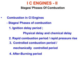
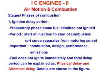
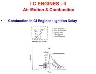
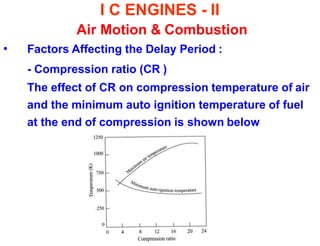
SlideShare a Scribd company logo
INTERNAL COMBUSTION ENGINES-II
Combustion
ARUNKUMAR.A
AP/MECH
I C ENGINES - II
Stages/ Phases Of Combustion
• Combustion in CI Engines
- Stages/ Phases of combustion
1. Ignition delay period ;
Physical delay and chemical delay
2. Rapid combustion period / rapid pressure rise
3. Controlled combustion period /
mechanically controlled period
4. After-Burning period
I C ENGINES - II
Air Motion & Combustion
• Combustion in CI Engines
I C ENGINES - II
Air Motion & Combustion
Stages/ Phases of combustion
1. Ignition delay period ;
-Preparatory phase:some fuel admitted,not ignited
-Period : start of injection to start of combustion
(p-t curve separates from motoring curve)
-Important : combustion, design, performance,
emissions
-Fuel does not ignite immediately and total delay
period can be explained as; Physical delay and
Chemical delay. Details are shown in the figure.
I C ENGINES - II
Air Motion & Combustion
• Combustion in CI Engines : Ignition Delay
I C ENGINES - II
Air Motion & Combustion
Stages/ Phases of combustion
Physical delay :
- period ; from beginning of injection to attainment
of chemical reactions.
- process; atomization, vaporization, mixing of fuel
& air, raising to self-ignition temperature
- depends on; fuel,air motion,combustion chamber
I C ENGINES - II
Air Motion & Combustion
Stages/ Phases of combustion
Chemical delay :
- Period ; from beginning of chemical reactions to
auto-ignition
- process ; pre-reactions in the mixture taking place
up to auto-ignition that occurs at a local
excess-air factor of 0.5 < λ < 0.7
-depends ; chemical reactions are faster at higher
temperature of the surroundings and accordingly
the chemical delay becomes shorter.
I C ENGINES - II
Air Motion & Combustion
Stages/ Phases of combustion
2. Rapid combustion period / rapid pressure rise
- period ; from end of delay or beginning of
combustion to the point of maximum pressure on
indicator diagram
-process ; most of the fuel would have formed
combustible mixture with air and preflame reactions
I C ENGINES - II
Air Motion & Combustion
Stages/ Phases of combustion
- depends ;
It may be noted that the maximum pressure
reached during this phase depends upon the delay
period. Longer the delay the higher is the rate of
pressure rise as more fuel gets accumulated
during the delay period.
I C ENGINES - II
Air Motion & Combustion
- Stages/ Phases of combustion
3. Controlled combustion period / mechanically
controlled period
-process ; This is the second phase of fuel injection
- period ; from the point of maximum pressure to
thepoint of maximum cycle temperature.
I C ENGINES - II
Air Motion & Combustion
-depends ; crank-angle duration of fuel injection as
per load requirements (higher and full load power
out-put ).
-Therefore, this is mechanically controlled by the
injection pump out put characteristics.
I C ENGINES - II
Air Motion & Combustion
4. After-Burning period : fuel with the air
- Combustion does not cease with completion of fuel
injection.The unburnt and partially burnt fuel particles
start burning as soon as they come in contact with
oxygen. This continue for a certain duration called
after- burning period.
- period ; starts from the point of max.cycle temp. and
continue over the part of expansion process.
- depends ; rate of after burning depends upon velocity
of diffusion and turbulent mixing of unburnt and
partially burnt fuel with the air
I C ENGINES - II
Air Motion & Combustion
I C ENGINES - II
Air Motion & Combustion
• Factors Affecting the Delay Period :
Many design and Operating factors affect the delay
period. Some of the significant factors are;
- Compression ratio
- Engine speed
- Output
- Atomization of fuel and duration of injection
- Injection timing
- Quality of fuel
- Intake temperature and pressure
I C ENGINES - II
Air Motion & Combustion
• Factors Affecting the Delay Period :
- Compression ratio (CR )
The effect of CR on compression temperature of air
and the minimum auto ignition temperature of fuel
at the end of compression is shown below
I C ENGINES - II
Air Motion & Combustion
• Factors Affecting the Delay Period :
- Engine speed :
The effect of engine speed on ID ( time ) is shown
below
I C ENGINES - II
Air Motion & Combustion
• Factors Affecting the Delay Period :
- Output :
With increase load or output, the amount of fuel
injected ( at constant rpm ) increases and therefore
the air-fuel decreases and results in increase in
temperature thereby reducing delay period.
I C ENGINES - II
Air Motion & Combustion
• Factors Affecting the Delay Period :
-Atomization of fuel and duration of injection :
Higher fuel-injection press. increases the degree
(fineness) of atomization which reduces ignition
delay due to higher surface to volume ratio.
-Smaller droplets have low depth of penetration due
to less momentum. Such droplets have less velocity
relative to air and shorter fuel spray path, where it
has to find oxygen after vaporization affecting air
utilization factor. Also the aggregate area of
inflammation after ignition will increase resulting in
I C ENGINES - II
Air Motion & Combustion
• Factors Affecting the Delay Period :
- Injection timing :
The effect of injection advance timings ( 9º,18º,27º )
for constant injected quantity of fuel on cylinder
pressure is shown below :
I C ENGINES - II
Air Motion & Combustion
• Factors Affecting the Delay Period :
-As pressure and temperature at the begning of
injection are lower for higher injection advance, the
delay period increases with increase in injection
advance.
-The optimum angle of advance depends on many
factors. Generally it is about 20º bTDC.
I C ENGINES - II
Air Motion & Combustion
• Factors Affecting the Delay Period :
-Quality of fuel
Self ignition temperature is the most important
property of fuel which affects the delay period. A
lower self-ignition temperature results in lower
delay period.
-Fuels with higher cetane number give lower delay.
Other properties of fuel which affect delay period
include volatility, latent heat, viscosity and surface
tension.
I C ENGINES - II
Air Motion & Combustion
• Factors Affecting the Delay Period :
-Intake temperature and pressure :
Increase in intake temp. increases compressed air
temp. resulting in reduced delay period. Preheating
may not be desirable as it reduces density of air
affecting volumetric efficiency and power.
-Increase in intake pressure reduces the auto -
ignition temp. and hence the delay period. The peak
pressure will be higher as compression pressure
will be higher with higher intake pressure.
I C ENGINES - II
Air Motion & Combustion
I C ENGINES - II
Air Motion & Combustion
I C ENGINES - II
Air Motion & Combustion
I C ENGINES - II
Air Motion & Combustion
• Knock in CI Engines :
-Fuel Injection takes definite interval
- Injection & Combustion take place simultaneously
-Initial droplets while undergoing ignition delay, additional
droplets are being injected
- If ignition delay of fuel is short,
initial few droplets will commence
actual burning
- As a result, mass rate of mixture
burned produce rate of press. rise
for soother combustion as shown
I C ENGINES - II
Air Motion & Combustion
• Knock in CI Engines :
- As ignition delay is longer , the actual burning of
first few droplets is delayed and accumulation of
greater quantity of fuel take place. When actual
burning take place under such conditions the rate of
pressure rise increases as shown in fig.
I C ENGINES - II
Air Motion & Combustion
• Knock in CI Engines :
- If ignition delay is quite large and the actual
burning is substantially delayed and the
accumulation of fuel is high when actual burning
take place the rate of pressure rise is almost
instantaneous the knocking begins as shown in fig.
I C ENGINES - II
Air Motion & Combustion
• Knock in CI Engines :
-Knocking is characterized by extreme pressure
differentials and violent gas vibrations evidenced by
audible knock.
-In CI engines knocking occurs in the beginning of
combustion.
-In order to decrease knocking the actual burning
should start as early as possible after the fuel
injection begins.
-It has been found that provided the rate of press.
rise does not exceed 3 bar per ºCA combustion is
I C ENGINES - II
Air Motion & Combustion
• Knock in CI Engines :
-smooth. Between 3 to 4 bar there is tendency to
knock, above this rate of pressure rise the diesel
knock will be prominent.
-Normally audible knock is always present in CI
engines, when it becomes sever and cause heavy
vibrations in the engine , it is said to be knocking. It
is, therefore, a matter of judgment.
-Low ignition temp., ignition delay & speed reduce
knock as also higher CR, Inlet Temp. & press.,
comb. wall temp. cylinder size
I C ENGINES - II Air Motion & Combustion
Combustion Chambers for C.I. Engines
 CI combustion chamber :
- provide proper mixing of fuel and air in short time
- An organized air movement ;
swirl, turbulence,squish
- produce high relative velocity between fuel
droplets and air
- Shape of combustion chamber control air motion
- CI engines classified as ;
Direct- Injection (DI) & Indirect- Injection (IDI)
I C ENGINES - II Air Motion & Combustion
Combustion Chambers for C.I. Engines
 CI combustion chamber :
Direct- Injection (DI)
- entire volume of combustion chamber located
in main cylinder where fuel is injected. Also
called open combustion chamber.
Indirect- Injection (IDI)
- Combustion space divided into two parts ;
one part main cyl. & other part in cylinder head
I C ENGINES - II Air Motion & Combustion
Combustion Chambers for C.I. Engines
 Indirect- Injection (IDI)
- Classified as :
1. Swirl chamber ;
compression swirl generated
2. Precombustion chamber ;
combustion swirl induced
3. Air cell chamber ;
compression & combustion swirl induced

More Related Content

What's hot

Centrifugal compressors-brochure
Centrifugal compressors-brochureCentrifugal compressors-brochure
Centrifugal compressors-brochure
R.V Koushik
 
IC ENGINE'S COMBUTION
IC ENGINE'S COMBUTION IC ENGINE'S COMBUTION
IC ENGINE'S COMBUTION
SKD CHITS
 
Thermo Structural Analysis on Cylinder Head of 4 Stroke VCR Diesel Engine
Thermo Structural Analysis on Cylinder Head of 4 Stroke VCR Diesel EngineThermo Structural Analysis on Cylinder Head of 4 Stroke VCR Diesel Engine
Thermo Structural Analysis on Cylinder Head of 4 Stroke VCR Diesel Engine
Dr. Amarjeet Singh
 
IRJET- Investigation of Performance and Emission Characteristics of CI En...
IRJET-  	  Investigation of Performance and Emission Characteristics of CI En...IRJET-  	  Investigation of Performance and Emission Characteristics of CI En...
IRJET- Investigation of Performance and Emission Characteristics of CI En...
IRJET Journal
 
Combustion in si engines
Combustion in si enginesCombustion in si engines
Combustion in si engines
Prasad Patil
 
Rotary compressors ppt
Rotary compressors pptRotary compressors ppt
I C ENGINE
I C ENGINEI C ENGINE
I C ENGINE
DEBOLINA MUKHERJEE
 
piston engine fuel system
piston engine fuel systempiston engine fuel system
piston engine fuel system
Rakesh Kotla
 
Compressor basis
Compressor basisCompressor basis
Compressor basis
Julián Sáez Mateo
 
Unit no 3 air compressor
Unit no 3 air compressorUnit no 3 air compressor
Unit no 3 air compressor
sandeshkrasal
 
Chapter 1 Introduction IC engines.pdf
Chapter 1 Introduction IC engines.pdfChapter 1 Introduction IC engines.pdf
Chapter 1 Introduction IC engines.pdf
ZiadAlaa2
 
centrifugal compressors overview
centrifugal compressors overviewcentrifugal compressors overview
centrifugal compressors overview
Usman Ali
 
Centrifugal compressor in IFFCO
Centrifugal compressor   in IFFCOCentrifugal compressor   in IFFCO
Centrifugal compressor in IFFCO
Anand Patel
 
Air copmressors
Air copmressorsAir copmressors
Air copmressors
Bhavesh Kankrecha
 
ME 6404 THERMAL ENGINEERING UNIT IV
ME 6404 THERMAL ENGINEERING UNIT IVME 6404 THERMAL ENGINEERING UNIT IV
ME 6404 THERMAL ENGINEERING UNIT IV
BIBIN CHIDAMBARANATHAN
 
Multi point fuel injection
Multi point fuel injectionMulti point fuel injection
Multi point fuel injection
Ravi Loriya
 
Positive crankcase ventilation
Positive crankcase ventilationPositive crankcase ventilation
Positive crankcase ventilationNizam Anuar
 
Fundamental of ic engine by asnh
Fundamental of ic engine by asnhFundamental of ic engine by asnh
Fundamental of ic engine by asnh
Avesahemad Husainy
 

What's hot (19)

Centrifugal compressors-brochure
Centrifugal compressors-brochureCentrifugal compressors-brochure
Centrifugal compressors-brochure
 
IC ENGINE'S COMBUTION
IC ENGINE'S COMBUTION IC ENGINE'S COMBUTION
IC ENGINE'S COMBUTION
 
Thermo Structural Analysis on Cylinder Head of 4 Stroke VCR Diesel Engine
Thermo Structural Analysis on Cylinder Head of 4 Stroke VCR Diesel EngineThermo Structural Analysis on Cylinder Head of 4 Stroke VCR Diesel Engine
Thermo Structural Analysis on Cylinder Head of 4 Stroke VCR Diesel Engine
 
IRJET- Investigation of Performance and Emission Characteristics of CI En...
IRJET-  	  Investigation of Performance and Emission Characteristics of CI En...IRJET-  	  Investigation of Performance and Emission Characteristics of CI En...
IRJET- Investigation of Performance and Emission Characteristics of CI En...
 
Combustion in si engines
Combustion in si enginesCombustion in si engines
Combustion in si engines
 
Rotary compressors ppt
Rotary compressors pptRotary compressors ppt
Rotary compressors ppt
 
I C ENGINE
I C ENGINEI C ENGINE
I C ENGINE
 
I c engines a study
I c engines a studyI c engines a study
I c engines a study
 
piston engine fuel system
piston engine fuel systempiston engine fuel system
piston engine fuel system
 
Compressor basis
Compressor basisCompressor basis
Compressor basis
 
Unit no 3 air compressor
Unit no 3 air compressorUnit no 3 air compressor
Unit no 3 air compressor
 
Chapter 1 Introduction IC engines.pdf
Chapter 1 Introduction IC engines.pdfChapter 1 Introduction IC engines.pdf
Chapter 1 Introduction IC engines.pdf
 
centrifugal compressors overview
centrifugal compressors overviewcentrifugal compressors overview
centrifugal compressors overview
 
Centrifugal compressor in IFFCO
Centrifugal compressor   in IFFCOCentrifugal compressor   in IFFCO
Centrifugal compressor in IFFCO
 
Air copmressors
Air copmressorsAir copmressors
Air copmressors
 
ME 6404 THERMAL ENGINEERING UNIT IV
ME 6404 THERMAL ENGINEERING UNIT IVME 6404 THERMAL ENGINEERING UNIT IV
ME 6404 THERMAL ENGINEERING UNIT IV
 
Multi point fuel injection
Multi point fuel injectionMulti point fuel injection
Multi point fuel injection
 
Positive crankcase ventilation
Positive crankcase ventilationPositive crankcase ventilation
Positive crankcase ventilation
 
Fundamental of ic engine by asnh
Fundamental of ic engine by asnhFundamental of ic engine by asnh
Fundamental of ic engine by asnh
 

Similar to Ci engine combustion chamber

CI engine combustion stages and combustion chamber design
CI engine combustion stages and combustion chamber designCI engine combustion stages and combustion chamber design
CI engine combustion stages and combustion chamber design
INDIAN INSTITUTE OF TECHNOLOGY Delhi
 
CI engine combustion stages and combustion chamber design
CI engine combustion stages and combustion chamber designCI engine combustion stages and combustion chamber design
CI engine combustion stages and combustion chamber design
INDIAN INSTITUTE OF TECHNOLOGY Delhi
 
AICE- UNIT-2.pptx
AICE- UNIT-2.pptxAICE- UNIT-2.pptx
AICE- UNIT-2.pptx
GunaSekaran958261
 
ATD CI ENGINE COMBUSTION PHENOMENON UNIT-3 PPT.ppt
ATD CI ENGINE COMBUSTION PHENOMENON UNIT-3 PPT.pptATD CI ENGINE COMBUSTION PHENOMENON UNIT-3 PPT.ppt
ATD CI ENGINE COMBUSTION PHENOMENON UNIT-3 PPT.ppt
AryanYadav553427
 
ATD CI ENGINE COMBUSTION PHENOMENON UNIT-3 PPT (1).ppt
ATD CI ENGINE COMBUSTION PHENOMENON UNIT-3 PPT (1).pptATD CI ENGINE COMBUSTION PHENOMENON UNIT-3 PPT (1).ppt
ATD CI ENGINE COMBUSTION PHENOMENON UNIT-3 PPT (1).ppt
hodmech18
 
compression egnition engine engine
compression egnition engine enginecompression egnition engine engine
compression egnition engine engine
naphis ahamad
 
FALLSEM2021-22_MEE1012_TH_VL2021220103336_Reference_Material_I_02-09-2021_CI_...
FALLSEM2021-22_MEE1012_TH_VL2021220103336_Reference_Material_I_02-09-2021_CI_...FALLSEM2021-22_MEE1012_TH_VL2021220103336_Reference_Material_I_02-09-2021_CI_...
FALLSEM2021-22_MEE1012_TH_VL2021220103336_Reference_Material_I_02-09-2021_CI_...
HarshVerma447237
 
ME6016 ADVANCED I.C.ENGINES
ME6016 ADVANCED I.C.ENGINESME6016 ADVANCED I.C.ENGINES
ME6016 ADVANCED I.C.ENGINES
books5884
 
UNIT-I SPARK IGNITION ENGINES.ppt
UNIT-I SPARK IGNITION ENGINES.pptUNIT-I SPARK IGNITION ENGINES.ppt
UNIT-I SPARK IGNITION ENGINES.ppt
Dr.G.Saravanan
 
Basics of IC engine
Basics of IC engineBasics of IC engine
Basics of IC engineSLA1987
 
AICE-Unit 2
AICE-Unit   2AICE-Unit   2
AICE-Unit 2
prakash0712
 
unit-2-COMPRESSION IGNITION engine system
unit-2-COMPRESSION IGNITION engine systemunit-2-COMPRESSION IGNITION engine system
unit-2-COMPRESSION IGNITION engine system
samy709581
 
Superchargers and Turbochargers
Superchargers and TurbochargersSuperchargers and Turbochargers
Superchargers and Turbochargers
Rajat Seth
 
ME6016 ADVANCED I.C ENGINES - SHORT QUESTIONS AND ANSWERS
ME6016 ADVANCED I.C ENGINES - SHORT QUESTIONS AND ANSWERSME6016 ADVANCED I.C ENGINES - SHORT QUESTIONS AND ANSWERS
ME6016 ADVANCED I.C ENGINES - SHORT QUESTIONS AND ANSWERS
BIBIN CHIDAMBARANATHAN
 
Combustion behaviour in Internal Combustion engines.ppt
Combustion behaviour in Internal Combustion engines.pptCombustion behaviour in Internal Combustion engines.ppt
Combustion behaviour in Internal Combustion engines.ppt
Ayisha586983
 
ICE Combustion PPT ICE Education-Academics
ICE Combustion PPT ICE Education-AcademicsICE Combustion PPT ICE Education-Academics
ICE Combustion PPT ICE Education-Academics
Bhosalesarkar
 
Basic of Combustion in CI Engines
Basic of Combustion in CI EnginesBasic of Combustion in CI Engines
Basic of Combustion in CI Engines
SACHINNikam39
 
AICE- UNIT-1.pptx
AICE- UNIT-1.pptxAICE- UNIT-1.pptx
AICE- UNIT-1.pptx
GunaSekaran958261
 
Air-Motion in Engine Cylinder
Air-Motion in Engine CylinderAir-Motion in Engine Cylinder
Air-Motion in Engine Cylinder
Rajat Seth
 
ICE_22_Chapter 4.v2.ppt
ICE_22_Chapter 4.v2.pptICE_22_Chapter 4.v2.ppt
ICE_22_Chapter 4.v2.ppt
ishi67
 

Similar to Ci engine combustion chamber (20)

CI engine combustion stages and combustion chamber design
CI engine combustion stages and combustion chamber designCI engine combustion stages and combustion chamber design
CI engine combustion stages and combustion chamber design
 
CI engine combustion stages and combustion chamber design
CI engine combustion stages and combustion chamber designCI engine combustion stages and combustion chamber design
CI engine combustion stages and combustion chamber design
 
AICE- UNIT-2.pptx
AICE- UNIT-2.pptxAICE- UNIT-2.pptx
AICE- UNIT-2.pptx
 
ATD CI ENGINE COMBUSTION PHENOMENON UNIT-3 PPT.ppt
ATD CI ENGINE COMBUSTION PHENOMENON UNIT-3 PPT.pptATD CI ENGINE COMBUSTION PHENOMENON UNIT-3 PPT.ppt
ATD CI ENGINE COMBUSTION PHENOMENON UNIT-3 PPT.ppt
 
ATD CI ENGINE COMBUSTION PHENOMENON UNIT-3 PPT (1).ppt
ATD CI ENGINE COMBUSTION PHENOMENON UNIT-3 PPT (1).pptATD CI ENGINE COMBUSTION PHENOMENON UNIT-3 PPT (1).ppt
ATD CI ENGINE COMBUSTION PHENOMENON UNIT-3 PPT (1).ppt
 
compression egnition engine engine
compression egnition engine enginecompression egnition engine engine
compression egnition engine engine
 
FALLSEM2021-22_MEE1012_TH_VL2021220103336_Reference_Material_I_02-09-2021_CI_...
FALLSEM2021-22_MEE1012_TH_VL2021220103336_Reference_Material_I_02-09-2021_CI_...FALLSEM2021-22_MEE1012_TH_VL2021220103336_Reference_Material_I_02-09-2021_CI_...
FALLSEM2021-22_MEE1012_TH_VL2021220103336_Reference_Material_I_02-09-2021_CI_...
 
ME6016 ADVANCED I.C.ENGINES
ME6016 ADVANCED I.C.ENGINESME6016 ADVANCED I.C.ENGINES
ME6016 ADVANCED I.C.ENGINES
 
UNIT-I SPARK IGNITION ENGINES.ppt
UNIT-I SPARK IGNITION ENGINES.pptUNIT-I SPARK IGNITION ENGINES.ppt
UNIT-I SPARK IGNITION ENGINES.ppt
 
Basics of IC engine
Basics of IC engineBasics of IC engine
Basics of IC engine
 
AICE-Unit 2
AICE-Unit   2AICE-Unit   2
AICE-Unit 2
 
unit-2-COMPRESSION IGNITION engine system
unit-2-COMPRESSION IGNITION engine systemunit-2-COMPRESSION IGNITION engine system
unit-2-COMPRESSION IGNITION engine system
 
Superchargers and Turbochargers
Superchargers and TurbochargersSuperchargers and Turbochargers
Superchargers and Turbochargers
 
ME6016 ADVANCED I.C ENGINES - SHORT QUESTIONS AND ANSWERS
ME6016 ADVANCED I.C ENGINES - SHORT QUESTIONS AND ANSWERSME6016 ADVANCED I.C ENGINES - SHORT QUESTIONS AND ANSWERS
ME6016 ADVANCED I.C ENGINES - SHORT QUESTIONS AND ANSWERS
 
Combustion behaviour in Internal Combustion engines.ppt
Combustion behaviour in Internal Combustion engines.pptCombustion behaviour in Internal Combustion engines.ppt
Combustion behaviour in Internal Combustion engines.ppt
 
ICE Combustion PPT ICE Education-Academics
ICE Combustion PPT ICE Education-AcademicsICE Combustion PPT ICE Education-Academics
ICE Combustion PPT ICE Education-Academics
 
Basic of Combustion in CI Engines
Basic of Combustion in CI EnginesBasic of Combustion in CI Engines
Basic of Combustion in CI Engines
 
AICE- UNIT-1.pptx
AICE- UNIT-1.pptxAICE- UNIT-1.pptx
AICE- UNIT-1.pptx
 
Air-Motion in Engine Cylinder
Air-Motion in Engine CylinderAir-Motion in Engine Cylinder
Air-Motion in Engine Cylinder
 
ICE_22_Chapter 4.v2.ppt
ICE_22_Chapter 4.v2.pptICE_22_Chapter 4.v2.ppt
ICE_22_Chapter 4.v2.ppt
 

Recently uploaded

Architectural Portfolio Sean Lockwood
Architectural Portfolio Sean LockwoodArchitectural Portfolio Sean Lockwood
Architectural Portfolio Sean Lockwood
seandesed
 
Planning Of Procurement o different goods and services
Planning Of Procurement o different goods and servicesPlanning Of Procurement o different goods and services
Planning Of Procurement o different goods and services
JoytuBarua2
 
The Benefits and Techniques of Trenchless Pipe Repair.pdf
The Benefits and Techniques of Trenchless Pipe Repair.pdfThe Benefits and Techniques of Trenchless Pipe Repair.pdf
The Benefits and Techniques of Trenchless Pipe Repair.pdf
Pipe Restoration Solutions
 
Water Industry Process Automation and Control Monthly - May 2024.pdf
Water Industry Process Automation and Control Monthly - May 2024.pdfWater Industry Process Automation and Control Monthly - May 2024.pdf
Water Industry Process Automation and Control Monthly - May 2024.pdf
Water Industry Process Automation & Control
 
Top 10 Oil and Gas Projects in Saudi Arabia 2024.pdf
Top 10 Oil and Gas Projects in Saudi Arabia 2024.pdfTop 10 Oil and Gas Projects in Saudi Arabia 2024.pdf
Top 10 Oil and Gas Projects in Saudi Arabia 2024.pdf
Teleport Manpower Consultant
 
block diagram and signal flow graph representation
block diagram and signal flow graph representationblock diagram and signal flow graph representation
block diagram and signal flow graph representation
Divya Somashekar
 
Pile Foundation by Venkatesh Taduvai (Sub Geotechnical Engineering II)-conver...
Pile Foundation by Venkatesh Taduvai (Sub Geotechnical Engineering II)-conver...Pile Foundation by Venkatesh Taduvai (Sub Geotechnical Engineering II)-conver...
Pile Foundation by Venkatesh Taduvai (Sub Geotechnical Engineering II)-conver...
AJAYKUMARPUND1
 
Runway Orientation Based on the Wind Rose Diagram.pptx
Runway Orientation Based on the Wind Rose Diagram.pptxRunway Orientation Based on the Wind Rose Diagram.pptx
Runway Orientation Based on the Wind Rose Diagram.pptx
SupreethSP4
 
ML for identifying fraud using open blockchain data.pptx
ML for identifying fraud using open blockchain data.pptxML for identifying fraud using open blockchain data.pptx
ML for identifying fraud using open blockchain data.pptx
Vijay Dialani, PhD
 
在线办理(ANU毕业证书)澳洲国立大学毕业证录取通知书一模一样
在线办理(ANU毕业证书)澳洲国立大学毕业证录取通知书一模一样在线办理(ANU毕业证书)澳洲国立大学毕业证录取通知书一模一样
在线办理(ANU毕业证书)澳洲国立大学毕业证录取通知书一模一样
obonagu
 
MCQ Soil mechanics questions (Soil shear strength).pdf
MCQ Soil mechanics questions (Soil shear strength).pdfMCQ Soil mechanics questions (Soil shear strength).pdf
MCQ Soil mechanics questions (Soil shear strength).pdf
Osamah Alsalih
 
Hybrid optimization of pumped hydro system and solar- Engr. Abdul-Azeez.pdf
Hybrid optimization of pumped hydro system and solar- Engr. Abdul-Azeez.pdfHybrid optimization of pumped hydro system and solar- Engr. Abdul-Azeez.pdf
Hybrid optimization of pumped hydro system and solar- Engr. Abdul-Azeez.pdf
fxintegritypublishin
 
ethical hacking in wireless-hacking1.ppt
ethical hacking in wireless-hacking1.pptethical hacking in wireless-hacking1.ppt
ethical hacking in wireless-hacking1.ppt
Jayaprasanna4
 
J.Yang, ICLR 2024, MLILAB, KAIST AI.pdf
J.Yang,  ICLR 2024, MLILAB, KAIST AI.pdfJ.Yang,  ICLR 2024, MLILAB, KAIST AI.pdf
J.Yang, ICLR 2024, MLILAB, KAIST AI.pdf
MLILAB
 
The role of big data in decision making.
The role of big data in decision making.The role of big data in decision making.
The role of big data in decision making.
ankuprajapati0525
 
road safety engineering r s e unit 3.pdf
road safety engineering  r s e unit 3.pdfroad safety engineering  r s e unit 3.pdf
road safety engineering r s e unit 3.pdf
VENKATESHvenky89705
 
Final project report on grocery store management system..pdf
Final project report on grocery store management system..pdfFinal project report on grocery store management system..pdf
Final project report on grocery store management system..pdf
Kamal Acharya
 
power quality voltage fluctuation UNIT - I.pptx
power quality voltage fluctuation UNIT - I.pptxpower quality voltage fluctuation UNIT - I.pptx
power quality voltage fluctuation UNIT - I.pptx
ViniHema
 
Investor-Presentation-Q1FY2024 investor presentation document.pptx
Investor-Presentation-Q1FY2024 investor presentation document.pptxInvestor-Presentation-Q1FY2024 investor presentation document.pptx
Investor-Presentation-Q1FY2024 investor presentation document.pptx
AmarGB2
 
WATER CRISIS and its solutions-pptx 1234
WATER CRISIS and its solutions-pptx 1234WATER CRISIS and its solutions-pptx 1234
WATER CRISIS and its solutions-pptx 1234
AafreenAbuthahir2
 

Recently uploaded (20)

Architectural Portfolio Sean Lockwood
Architectural Portfolio Sean LockwoodArchitectural Portfolio Sean Lockwood
Architectural Portfolio Sean Lockwood
 
Planning Of Procurement o different goods and services
Planning Of Procurement o different goods and servicesPlanning Of Procurement o different goods and services
Planning Of Procurement o different goods and services
 
The Benefits and Techniques of Trenchless Pipe Repair.pdf
The Benefits and Techniques of Trenchless Pipe Repair.pdfThe Benefits and Techniques of Trenchless Pipe Repair.pdf
The Benefits and Techniques of Trenchless Pipe Repair.pdf
 
Water Industry Process Automation and Control Monthly - May 2024.pdf
Water Industry Process Automation and Control Monthly - May 2024.pdfWater Industry Process Automation and Control Monthly - May 2024.pdf
Water Industry Process Automation and Control Monthly - May 2024.pdf
 
Top 10 Oil and Gas Projects in Saudi Arabia 2024.pdf
Top 10 Oil and Gas Projects in Saudi Arabia 2024.pdfTop 10 Oil and Gas Projects in Saudi Arabia 2024.pdf
Top 10 Oil and Gas Projects in Saudi Arabia 2024.pdf
 
block diagram and signal flow graph representation
block diagram and signal flow graph representationblock diagram and signal flow graph representation
block diagram and signal flow graph representation
 
Pile Foundation by Venkatesh Taduvai (Sub Geotechnical Engineering II)-conver...
Pile Foundation by Venkatesh Taduvai (Sub Geotechnical Engineering II)-conver...Pile Foundation by Venkatesh Taduvai (Sub Geotechnical Engineering II)-conver...
Pile Foundation by Venkatesh Taduvai (Sub Geotechnical Engineering II)-conver...
 
Runway Orientation Based on the Wind Rose Diagram.pptx
Runway Orientation Based on the Wind Rose Diagram.pptxRunway Orientation Based on the Wind Rose Diagram.pptx
Runway Orientation Based on the Wind Rose Diagram.pptx
 
ML for identifying fraud using open blockchain data.pptx
ML for identifying fraud using open blockchain data.pptxML for identifying fraud using open blockchain data.pptx
ML for identifying fraud using open blockchain data.pptx
 
在线办理(ANU毕业证书)澳洲国立大学毕业证录取通知书一模一样
在线办理(ANU毕业证书)澳洲国立大学毕业证录取通知书一模一样在线办理(ANU毕业证书)澳洲国立大学毕业证录取通知书一模一样
在线办理(ANU毕业证书)澳洲国立大学毕业证录取通知书一模一样
 
MCQ Soil mechanics questions (Soil shear strength).pdf
MCQ Soil mechanics questions (Soil shear strength).pdfMCQ Soil mechanics questions (Soil shear strength).pdf
MCQ Soil mechanics questions (Soil shear strength).pdf
 
Hybrid optimization of pumped hydro system and solar- Engr. Abdul-Azeez.pdf
Hybrid optimization of pumped hydro system and solar- Engr. Abdul-Azeez.pdfHybrid optimization of pumped hydro system and solar- Engr. Abdul-Azeez.pdf
Hybrid optimization of pumped hydro system and solar- Engr. Abdul-Azeez.pdf
 
ethical hacking in wireless-hacking1.ppt
ethical hacking in wireless-hacking1.pptethical hacking in wireless-hacking1.ppt
ethical hacking in wireless-hacking1.ppt
 
J.Yang, ICLR 2024, MLILAB, KAIST AI.pdf
J.Yang,  ICLR 2024, MLILAB, KAIST AI.pdfJ.Yang,  ICLR 2024, MLILAB, KAIST AI.pdf
J.Yang, ICLR 2024, MLILAB, KAIST AI.pdf
 
The role of big data in decision making.
The role of big data in decision making.The role of big data in decision making.
The role of big data in decision making.
 
road safety engineering r s e unit 3.pdf
road safety engineering  r s e unit 3.pdfroad safety engineering  r s e unit 3.pdf
road safety engineering r s e unit 3.pdf
 
Final project report on grocery store management system..pdf
Final project report on grocery store management system..pdfFinal project report on grocery store management system..pdf
Final project report on grocery store management system..pdf
 
power quality voltage fluctuation UNIT - I.pptx
power quality voltage fluctuation UNIT - I.pptxpower quality voltage fluctuation UNIT - I.pptx
power quality voltage fluctuation UNIT - I.pptx
 
Investor-Presentation-Q1FY2024 investor presentation document.pptx
Investor-Presentation-Q1FY2024 investor presentation document.pptxInvestor-Presentation-Q1FY2024 investor presentation document.pptx
Investor-Presentation-Q1FY2024 investor presentation document.pptx
 
WATER CRISIS and its solutions-pptx 1234
WATER CRISIS and its solutions-pptx 1234WATER CRISIS and its solutions-pptx 1234
WATER CRISIS and its solutions-pptx 1234
 

Ci engine combustion chamber

  • 2. I C ENGINES - II Stages/ Phases Of Combustion • Combustion in CI Engines - Stages/ Phases of combustion 1. Ignition delay period ; Physical delay and chemical delay 2. Rapid combustion period / rapid pressure rise 3. Controlled combustion period / mechanically controlled period 4. After-Burning period
  • 3. I C ENGINES - II Air Motion & Combustion • Combustion in CI Engines
  • 4. I C ENGINES - II Air Motion & Combustion Stages/ Phases of combustion 1. Ignition delay period ; -Preparatory phase:some fuel admitted,not ignited -Period : start of injection to start of combustion (p-t curve separates from motoring curve) -Important : combustion, design, performance, emissions -Fuel does not ignite immediately and total delay period can be explained as; Physical delay and Chemical delay. Details are shown in the figure.
  • 5. I C ENGINES - II Air Motion & Combustion • Combustion in CI Engines : Ignition Delay
  • 6. I C ENGINES - II Air Motion & Combustion Stages/ Phases of combustion Physical delay : - period ; from beginning of injection to attainment of chemical reactions. - process; atomization, vaporization, mixing of fuel & air, raising to self-ignition temperature - depends on; fuel,air motion,combustion chamber
  • 7. I C ENGINES - II Air Motion & Combustion Stages/ Phases of combustion Chemical delay : - Period ; from beginning of chemical reactions to auto-ignition - process ; pre-reactions in the mixture taking place up to auto-ignition that occurs at a local excess-air factor of 0.5 < λ < 0.7 -depends ; chemical reactions are faster at higher temperature of the surroundings and accordingly the chemical delay becomes shorter.
  • 8. I C ENGINES - II Air Motion & Combustion Stages/ Phases of combustion 2. Rapid combustion period / rapid pressure rise - period ; from end of delay or beginning of combustion to the point of maximum pressure on indicator diagram -process ; most of the fuel would have formed combustible mixture with air and preflame reactions
  • 9. I C ENGINES - II Air Motion & Combustion Stages/ Phases of combustion - depends ; It may be noted that the maximum pressure reached during this phase depends upon the delay period. Longer the delay the higher is the rate of pressure rise as more fuel gets accumulated during the delay period.
  • 10. I C ENGINES - II Air Motion & Combustion - Stages/ Phases of combustion 3. Controlled combustion period / mechanically controlled period -process ; This is the second phase of fuel injection - period ; from the point of maximum pressure to thepoint of maximum cycle temperature.
  • 11. I C ENGINES - II Air Motion & Combustion -depends ; crank-angle duration of fuel injection as per load requirements (higher and full load power out-put ). -Therefore, this is mechanically controlled by the injection pump out put characteristics.
  • 12. I C ENGINES - II Air Motion & Combustion 4. After-Burning period : fuel with the air - Combustion does not cease with completion of fuel injection.The unburnt and partially burnt fuel particles start burning as soon as they come in contact with oxygen. This continue for a certain duration called after- burning period. - period ; starts from the point of max.cycle temp. and continue over the part of expansion process. - depends ; rate of after burning depends upon velocity of diffusion and turbulent mixing of unburnt and partially burnt fuel with the air
  • 13. I C ENGINES - II Air Motion & Combustion
  • 14. I C ENGINES - II Air Motion & Combustion • Factors Affecting the Delay Period : Many design and Operating factors affect the delay period. Some of the significant factors are; - Compression ratio - Engine speed - Output - Atomization of fuel and duration of injection - Injection timing - Quality of fuel - Intake temperature and pressure
  • 15. I C ENGINES - II Air Motion & Combustion • Factors Affecting the Delay Period : - Compression ratio (CR ) The effect of CR on compression temperature of air and the minimum auto ignition temperature of fuel at the end of compression is shown below
  • 16. I C ENGINES - II Air Motion & Combustion • Factors Affecting the Delay Period : - Engine speed : The effect of engine speed on ID ( time ) is shown below
  • 17. I C ENGINES - II Air Motion & Combustion • Factors Affecting the Delay Period : - Output : With increase load or output, the amount of fuel injected ( at constant rpm ) increases and therefore the air-fuel decreases and results in increase in temperature thereby reducing delay period.
  • 18. I C ENGINES - II Air Motion & Combustion • Factors Affecting the Delay Period : -Atomization of fuel and duration of injection : Higher fuel-injection press. increases the degree (fineness) of atomization which reduces ignition delay due to higher surface to volume ratio. -Smaller droplets have low depth of penetration due to less momentum. Such droplets have less velocity relative to air and shorter fuel spray path, where it has to find oxygen after vaporization affecting air utilization factor. Also the aggregate area of inflammation after ignition will increase resulting in
  • 19. I C ENGINES - II Air Motion & Combustion • Factors Affecting the Delay Period : - Injection timing : The effect of injection advance timings ( 9º,18º,27º ) for constant injected quantity of fuel on cylinder pressure is shown below :
  • 20. I C ENGINES - II Air Motion & Combustion • Factors Affecting the Delay Period : -As pressure and temperature at the begning of injection are lower for higher injection advance, the delay period increases with increase in injection advance. -The optimum angle of advance depends on many factors. Generally it is about 20º bTDC.
  • 21. I C ENGINES - II Air Motion & Combustion • Factors Affecting the Delay Period : -Quality of fuel Self ignition temperature is the most important property of fuel which affects the delay period. A lower self-ignition temperature results in lower delay period. -Fuels with higher cetane number give lower delay. Other properties of fuel which affect delay period include volatility, latent heat, viscosity and surface tension.
  • 22. I C ENGINES - II Air Motion & Combustion • Factors Affecting the Delay Period : -Intake temperature and pressure : Increase in intake temp. increases compressed air temp. resulting in reduced delay period. Preheating may not be desirable as it reduces density of air affecting volumetric efficiency and power. -Increase in intake pressure reduces the auto - ignition temp. and hence the delay period. The peak pressure will be higher as compression pressure will be higher with higher intake pressure.
  • 23. I C ENGINES - II Air Motion & Combustion
  • 24. I C ENGINES - II Air Motion & Combustion
  • 25. I C ENGINES - II Air Motion & Combustion
  • 26. I C ENGINES - II Air Motion & Combustion • Knock in CI Engines : -Fuel Injection takes definite interval - Injection & Combustion take place simultaneously -Initial droplets while undergoing ignition delay, additional droplets are being injected - If ignition delay of fuel is short, initial few droplets will commence actual burning - As a result, mass rate of mixture burned produce rate of press. rise for soother combustion as shown
  • 27. I C ENGINES - II Air Motion & Combustion • Knock in CI Engines : - As ignition delay is longer , the actual burning of first few droplets is delayed and accumulation of greater quantity of fuel take place. When actual burning take place under such conditions the rate of pressure rise increases as shown in fig.
  • 28. I C ENGINES - II Air Motion & Combustion • Knock in CI Engines : - If ignition delay is quite large and the actual burning is substantially delayed and the accumulation of fuel is high when actual burning take place the rate of pressure rise is almost instantaneous the knocking begins as shown in fig.
  • 29. I C ENGINES - II Air Motion & Combustion • Knock in CI Engines : -Knocking is characterized by extreme pressure differentials and violent gas vibrations evidenced by audible knock. -In CI engines knocking occurs in the beginning of combustion. -In order to decrease knocking the actual burning should start as early as possible after the fuel injection begins. -It has been found that provided the rate of press. rise does not exceed 3 bar per ºCA combustion is
  • 30. I C ENGINES - II Air Motion & Combustion • Knock in CI Engines : -smooth. Between 3 to 4 bar there is tendency to knock, above this rate of pressure rise the diesel knock will be prominent. -Normally audible knock is always present in CI engines, when it becomes sever and cause heavy vibrations in the engine , it is said to be knocking. It is, therefore, a matter of judgment. -Low ignition temp., ignition delay & speed reduce knock as also higher CR, Inlet Temp. & press., comb. wall temp. cylinder size
  • 31. I C ENGINES - II Air Motion & Combustion Combustion Chambers for C.I. Engines  CI combustion chamber : - provide proper mixing of fuel and air in short time - An organized air movement ; swirl, turbulence,squish - produce high relative velocity between fuel droplets and air - Shape of combustion chamber control air motion - CI engines classified as ; Direct- Injection (DI) & Indirect- Injection (IDI)
  • 32. I C ENGINES - II Air Motion & Combustion Combustion Chambers for C.I. Engines  CI combustion chamber : Direct- Injection (DI) - entire volume of combustion chamber located in main cylinder where fuel is injected. Also called open combustion chamber. Indirect- Injection (IDI) - Combustion space divided into two parts ; one part main cyl. & other part in cylinder head
  • 33. I C ENGINES - II Air Motion & Combustion Combustion Chambers for C.I. Engines  Indirect- Injection (IDI) - Classified as : 1. Swirl chamber ; compression swirl generated 2. Precombustion chamber ; combustion swirl induced 3. Air cell chamber ; compression & combustion swirl induced