CONTENTS
• Internship Details
•Objectives
• Introduction
•
• Brief About Aarti Industry
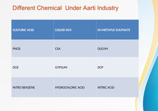
• Production Range
• Utility Maintenance
• Water treatment plant
• Outcomes
• Conclusions
3.
Objectives
Technical Objectives :
1.Gain improvement in SAP system.
2 . Learn industry-based standard practices like kaizen and 5S" activity.
Soft Skill Objectives:
1 . Improving communication and presentation skills.
2. Learn problem solving and thunking abilities.
Personal Growth Objectives :
1 . Contribute to the compnay and its goals.
2 . Gain valuable industry experience and build a professional work.
3 . Gain Knowledge industry working culture and gain experience equipments.
4.
Internship Details
• CompanyName - Aarti Industries LTD Vapi
• External Guide - Sudhir Gupta
• Internal Guide - Hemant Patel
• Department - Utility Maintenance / Engg. Department
• Role : intern/ Trainee
• Location: Vapi
• From : 19/03/2025 to 19/04/2025
• Working Hour : 09:00 AM To 17:30 PM
Introduction of Chillingplant
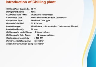
Chiiling Plant Cappicity : 60 TR
Refrigrerant Name : 134A
COMPRESSOR TYPE : Dual srew compressor
Condensor Type : Water shell and tube type Condensor
Evoporator Type : Shell and Tube type
Hot and Cold Well : 30 M2 Area
Insulation type : Nitraile type cold insulation ( thick ness - 50 mm)
Insulation Density : 60 mm
Chilling water outlet Temp. : 7 deree celcius
Chilling water inlet Temp. : 12 degree celceus
Cooling tower cappicity : 100 TR
Primary circulation pump : 35 m3/hr
Secondary circulation pump : 35 m3/hr
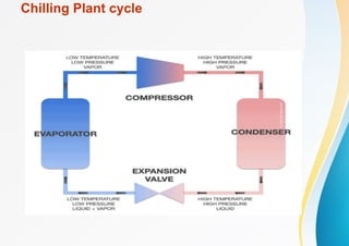
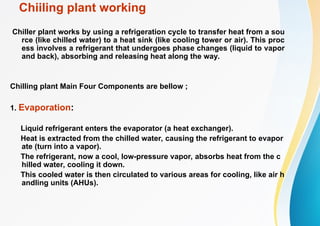
Chiiling plant working
Chillerplant works by using a refrigeration cycle to transfer heat from a sou
rce (like chilled water) to a heat sink (like cooling tower or air). This proc
ess involves a refrigerant that undergoes phase changes (liquid to vapor
and back), absorbing and releasing heat along the way.
Chilling plant Main Four Components are bellow ;
1. Evaporation:
Liquid refrigerant enters the evaporator (a heat exchanger).
Heat is extracted from the chilled water, causing the refrigerant to evapor
ate (turn into a vapor).
The refrigerant, now a cool, low-pressure vapor, absorbs heat from the c
hilled water, cooling it down.
This cooled water is then circulated to various areas for cooling, like air h
andling units (AHUs).
12.
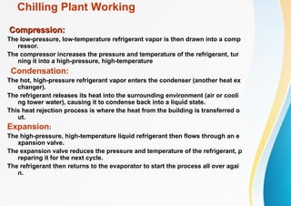
Chilling Plant Working
Compression:
Compression:
Thelow-pressure, low-temperature refrigerant vapor is then drawn into a comp
ressor.
The compressor increases the pressure and temperature of the refrigerant, tur
ning it into a high-pressure, high-temperature
Condensation:
The hot, high-pressure refrigerant vapor enters the condenser (another heat ex
changer).
The refrigerant releases its heat into the surrounding environment (air or cooli
ng tower water), causing it to condense back into a liquid state.
This heat rejection process is where the heat from the building is transferred o
ut.
Expansion:
The high-pressure, high-temperature liquid refrigerant then flows through an e
xpansion valve.
The expansion valve reduces the pressure and temperature of the refrigerant, p
reparing it for the next cycle.
The refrigerant then returns to the evaporator to start the process all over agai
n.
13.
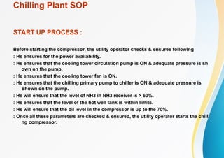
Chilling Plant SOP
STARTUP PROCESS :
Before starting the compressor, the utility operator checks & ensures following
: He ensures for the power availability.
: He ensures that the cooling tower circulation pump is ON & adequate pressure is sh
own on the pump.
: He ensures that the cooling tower fan is ON.
: He ensures that the chilling primary pump to chiller is ON & adequate pressure is
Shown on the pump.
: He will ensure that the level of NH3 in NH3 receiver is > 60%.
: He ensures that the level of the hot well tank is within limits.
: He will ensure that the oil level in the compressor is up to the 70%.
: Once all these parameters are checked & ensured, the utility operator starts the chilli
ng compressor.
Howden Blower inAcid Plants
15
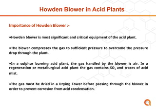
Importance of Howden Blower :-
●Howden blower is most significant and critical equipment of the acid plant.
●The blower compresses the gas to sufficient pressure to overcome the pressure
drop through the plant.
●In a sulphur burning acid plant, the gas handled by the blower is air. In a
regeneration or metallurgical acid plant the gas contains SO2
and traces of acid
mist.
●The gas must be dried in a Drying Tower before passing through the blower in
order to prevent corrosion from acid condensation.
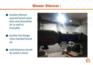
Blower Silencer :
●Suction Silencer
opened found some
dust and cleaned by
air as well as
manually.
● Suction line flange
raise checked found
ok.
● wall thickness found
ok which is 6mm
18
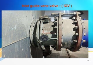
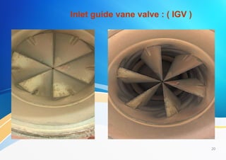
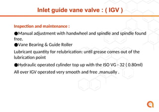
Inlet guide vanevalve : ( IGV )
21
Inspection and maintenance :
●Manual adjustment with handwheel and spindle and spindle found
free.
●Vane Bearing & Guide Roller
Lubricant quantity for relubrication: until grease comes out of the
lubrication point
●Hydraulic operated cylinder top up with the ISO VG - 32 ( 0.80ml)
All over IGV operated very smooth and free ,manually .
22.
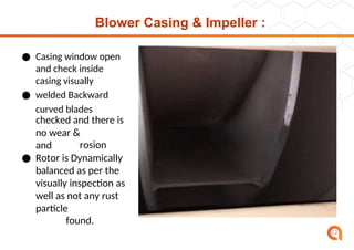
Blower Casing &Impeller :
● Casing window open
and check inside
casing visually
● welded Backward
curved blades
checked and there is
no wear &
corrosion
and
cr
ac
k.
● Rotor is Dynamically
balanced as per the
visually inspection as
well as not any rust
or
particle
found.
22
23.
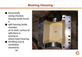
Bearing Housing :
●horizontally
split
casing checked,
split
housing inside found
o
k
● split housing inside
chamber
Cleaned by
air & cloth, surface of
split.there is
no
scoring or
marking
where insert bearing.
● Oil filling vent &
ventilation
filter
cleaned by
air.
23
24.
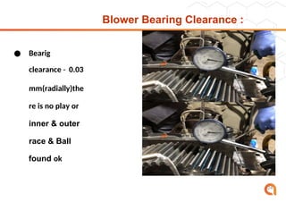
Blower Bearing Clearance:
● Bearig
clearance - 0.03
mm(radially)the
re is no play or
inner & outer
race & Ball
found ok
24
25.
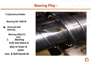
Bearing Play :
1.CylindricalRoller
Bearing NU 1026 M
● Grooved ball
bearing
Bearing 6222.C3
SKF
2. .Bearing
clearance - <
0.05 mm there is
no
play or inner &
outer
race & Ball found ok
25
26.
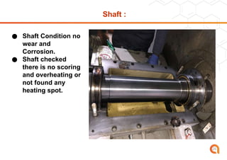
Shaft :
● ShaftCondition no
wear and
Corrosion.
● Shaft checked
there is no scoring
and overheating or
not found any
heating spot.
26
27.
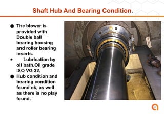
Shaft Hub AndBearing Condition.
● The blower is
provided with
Double ball
bearing housing
and roller bearing
inserts.
● Lubrication by
oil bath.Oil grade
ISO VG 32.
● Hub condition and
bearing condition
found ok, as well
as there is no play
found.
27
28.
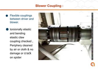
Blower Coupling :
●Flexible couplings
between driver and
blower.
● torsionally elastic
and bending
elastic claw
coupling checked ,
Periphery cleaned
by air or cloth & no
damage or crack
on spider.
28
29.
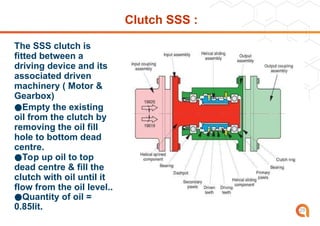
Clutch SSS :
TheSSS clutch is
fitted between a
driving device and its
associated driven
machinery ( Motor &
Gearbox)
●Empty the existing
oil from the clutch by
removing the oil fill
hole to bottom dead
centre.
●Top up oil to top
dead centre & fill the
clutch with oil until it
flow from the oil level..
●Quantity of oil =
0.85lit. 29
30.
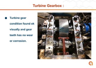
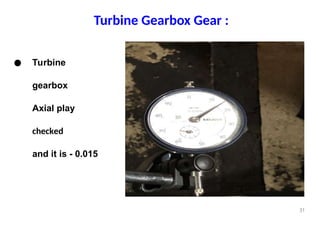
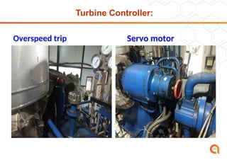
Turbine Gearbox :
●Turbine gear
condition found ok
visually and gear
teeth has no wear
or corrosion.
30
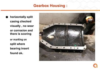
Gearbox Housing :
●horizontally split
casing checked
visually , no wear
or corrosion and
there is scoring
or marking on
split where
bearing insert
found ok.
34
35.
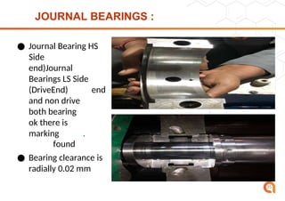
JOURNAL BEARINGS :
●Journal Bearing HS
Side
(Dri
ve
end)Journal
Bearings LS Side
(DriveEnd)
Drive
end
and non drive
end
both bearing
found
ok there is
no
marking
found
.
● Bearing clearance is
radially 0.02 mm
35
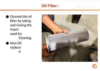
Oil Filter :
●Cleaned the oil
filter by taking
out
and rinsing the
insert
gasoline
used for
Cleaning.
● New Oil
filter
replace
d
37
38.
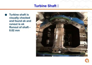
Turbine Shaft :
●Turbine shaft is
visually checked
and found ok and
runout is ok
Runout of shaft -
0.02 mm
38
39.
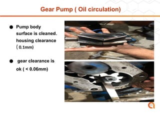
Gear Pump (Oil circulation)
● Pump body
surface is cleaned.
housing clearance
( 0.1mm)
● gear clearance is
ok ( < 0.06mm)
39
40.
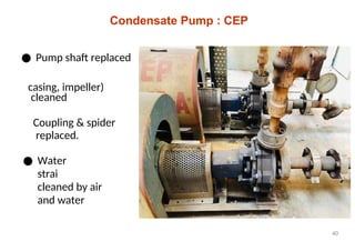
Condensate Pump :CEP
● Pump shaft replaced
cleaned
casing, impeller)
Coupling & spider
replaced.
● Water pump
strainner
cleaned by air
and water
40
41.
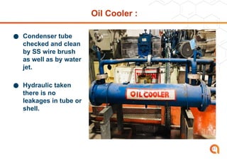
Oil Cooler :
●Condenser tube
checked and clean
by SS wire brush
as well as by water
jet.
● Hydraulic taken
there is no
leakages in tube or
shell.
41
42.
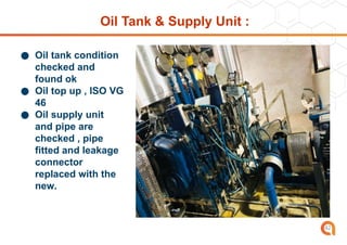
Oil Tank &Supply Unit :
● Oil tank condition
checked and
found ok
● Oil top up , ISO VG
46
● Oil supply unit
and pipe are
checked , pipe
fitted and leakage
connector
replaced with the
new.
42
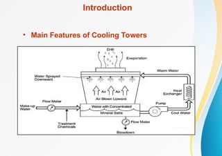
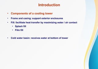
Introduction
• Components ofa cooling tower
• Frame and casing: support exterior enclosures
• Fill: facilitate heat transfer by maximizing water / air contact
• Splash fill
• Film fill
• Cold water basin: receives water at bottom of tower
47.
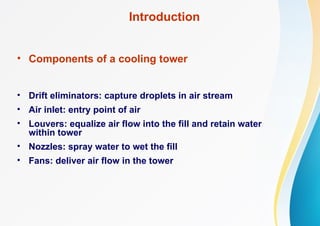
Introduction
• Components ofa cooling tower
• Drift eliminators: capture droplets in air stream
• Air inlet: entry point of air
• Louvers: equalize air flow into the fill and retain water
within tower
• Nozzles: spray water to wet the fill
• Fans: deliver air flow in the tower
48.
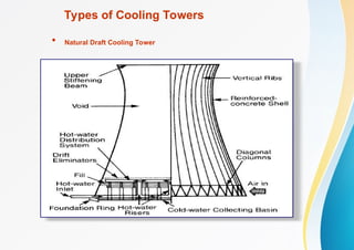
Types of CoolingTowers
• Natural Draft Cooling Towers
• Hot air moves through tower
• Fresh cool air is drawn into the tower from bottom
• No fan required
• Concrete tower <200 m
• Used for large heat duties
Types of CoolingTowers
• Mechanical Draft Cooling Towers
Large fans to force air through circulated water.
Water falls over fill surfaces: maximum heat transfer.
Cooling rates depend on many parameters
Can be grouped, e.g. 8-cell tower
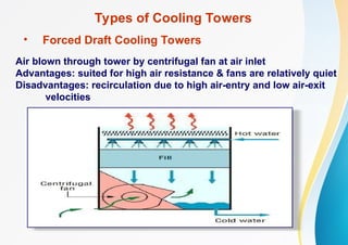
Types of CoolingTowers
• Forced Draft Cooling Towers
Air blown through tower by centrifugal fan at air inlet
Advantages: suited for high air resistance & fans are relatively quiet
Disadvantages: recirculation due to high air-entry and low air-exit
velocities
53.
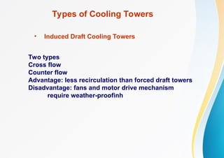
Types of CoolingTowers
• Induced Draft Cooling Towers
Two types
Cross flow
Counter flow
Advantage: less recirculation than forced draft towers
Disadvantage: fans and motor drive mechanism
require weather-proofinh
54.
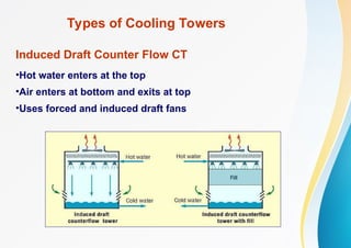
Types of CoolingTowers
Induced Draft Counter Flow CT
•Hot water enters at the top
•Air enters at bottom and exits at top
•Uses forced and induced draft fans
55.
Types of CoolingTowers
• Water enters top and passes over fill
• Air enters on one side or opposite sides
• Induced draft fan draws air across fill
Induced Draft Cross Flow CT
56.
Assessment of CoolingTowers
Measured Parameters
•Wet bulb temperature of air
•Dry bulb temperature of air
•Cooling tower inlet water temperature
•Cooling tower outlet water temperature
•Exhaust air temperature
•Electrical readings of pump and fan motors
•Water flow rate
•Air flow rate
57.
Assessment of CoolingTowers
Performance Parameters
1. Range
1.Approach
2.Effectiveness
3.Cooling capacity
4.Evaporation loss
5.Cycles of concentration
6.Blow down losses
•Liquid / Gas ratio
58.
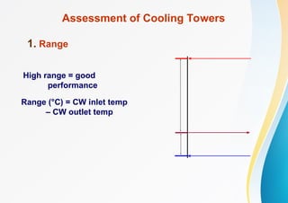
Assessment of CoolingTowers
1. Range
Range (°C) = CW inlet temp
– CW outlet temp
High range = good
performance
59.
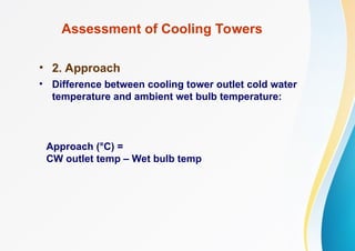
Assessment of CoolingTowers
• 2. Approach
• Difference between cooling tower outlet cold water
temperature and ambient wet bulb temperature:
Approach (°C) =
CW outlet temp – Wet bulb temp
60.
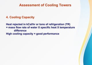
Assessment of CoolingTowers
4. Cooling Capacity
Heat rejected in kCal/hr or tons of refrigeration (TR)
= mass flow rate of water X specific heat X temperature
difference
High cooling capacity = good performance
61.
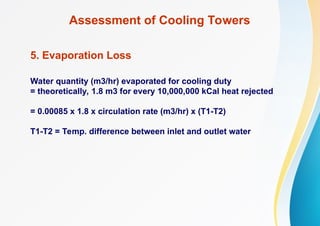
Assessment of CoolingTowers
5. Evaporation Loss
Water quantity (m3/hr) evaporated for cooling duty
= theoretically, 1.8 m3 for every 10,000,000 kCal heat rejected
= 0.00085 x 1.8 x circulation rate (m3/hr) x (T1-T2)
T1-T2 = Temp. difference between inlet and outlet water
62.
Assessment of CoolingTowers
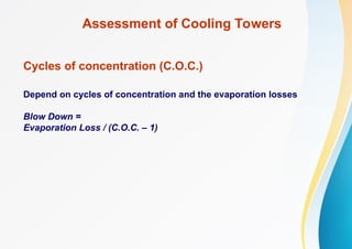
Cycles of concentration (C.O.C.)
Depend on cycles of concentration and the evaporation losses
Blow Down =
Evaporation Loss / (C.O.C. – 1)
63.
Assessment of CoolingTowers
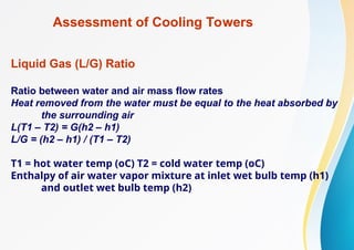
Liquid Gas (L/G) Ratio
Ratio between water and air mass flow rates
Heat removed from the water must be equal to the heat absorbed by
the surrounding air
L(T1 – T2) = G(h2 – h1)
L/G = (h2 – h1) / (T1 – T2)
T1 = hot water temp (oC) T2 = cold water temp (oC)
Enthalpy of air water vapor mixture at inlet wet bulb temp (h1)
and outlet wet bulb temp (h2)
Energy Efficiency Opportunities
1.Selecting a cooling tower
Range
Range
Range determined by process, not by system
Approach
Closer to the wet bulb temperature
Bigger size cooling tower
More expensive
66.
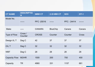
CT NAME
DESCRIPTIO
N
6MW CT2.35 MW CT SO3 OT-1
Model No.
------ PFC -25516 ------ PFC - 24414 -------
Make ----- CANARA BlueChip Canara Canara
Type of Flow
Cross /
Counter
CROSS Counter Counter Cross
Design I/L T Deg C 42 37 37 37
O/L T Deg C 32 32 32 32
WBT Deg C 28 28 28 28
Capacity Flow M3/HR 1500 200 700 400
Capacity TR 4960 331 1157 661
Zero Liquid Dischrge
:Zero liquid discharge (ZLD) refers to a treatment process in
which the plant discharges no liquid effluent into surface
waters, in effect completely eliminating the environmental
pollution associated with treatment.
: In Aarti Industry zld system are given bellow,
: MEE Plant ( Multi effect evoporative plant)
: ATFD ( Agitator thin filter dryer )
: ETP ( Effuilent treatment plant)
69.
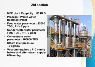
Zld section
• MEEplant Cappicity : 80 KLD
• Process : Waste water
treatment Plant
• Feed water parameter : 25000
TDS , PH - 7 ppm
• Condenstate water parameter
: 800 TDS , PH - 7 ppm
• Consentrate water
paremeter : 100000 TDS
• Steam inlet pressure :
2 kg/cm2
• Vacuum required : 710 mmhg
before and after steam supply
680 mmhg
70.
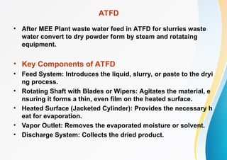
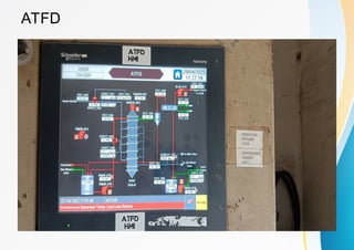
ATFD
• After MEEPlant waste water feed in ATFD for slurries waste
water convert to dry powder form by steam and rotataing
equipment.
• Key Components of ATFD
• Feed System: Introduces the liquid, slurry, or paste to the dryi
ng process.
• Rotating Shaft with Blades or Wipers: Agitates the material, e
nsuring it forms a thin, even film on the heated surface.
• Heated Surface (Jacketed Cylinder): Provides the necessary h
eat for evaporation.
• Vapor Outlet: Removes the evaporated moisture or solvent.
• Discharge System: Collects the dried product.
Outcomes
• Through my90 day internship , I have learnt how to handle
with real work time conditions.
• Also how maintaining relations with your seniors and
batchmates help you grow into your job.They can guide you
whenever you are stuck at situations.
• It helped me gain insights on to day to day oprations and
maintenance.
• I got traditional working culture and eniornment.
• My guide helped me how to apply theoretical knowledge to
pratical knowledge.
73.
CONCLUSION
• The SummerInternship was more than learning experience
for me. I got learnt about real work time conditions and learnt
them. Learnt about how to handle pressure and how
maintaining relations with collegues and seniors is important
in your job.
• The overall experience was fun and learing in many ways.