This document provides installation, start-up and service instructions for liquid chillers. It describes safety considerations that must be followed when working on the equipment. The document outlines 5 steps for installation, which include rigging and placing the unit, checking compressor mounting, making cooler fluid and drain piping connections, making electrical connections, and installing accessories. It also provides information on pre-start-up checks, start-up procedures, operation, service diagnostics, and a start-up checklist.

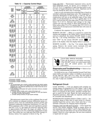
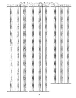
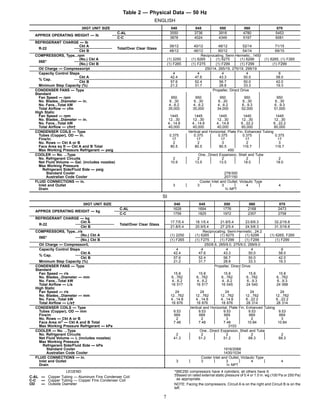
![LEGEND
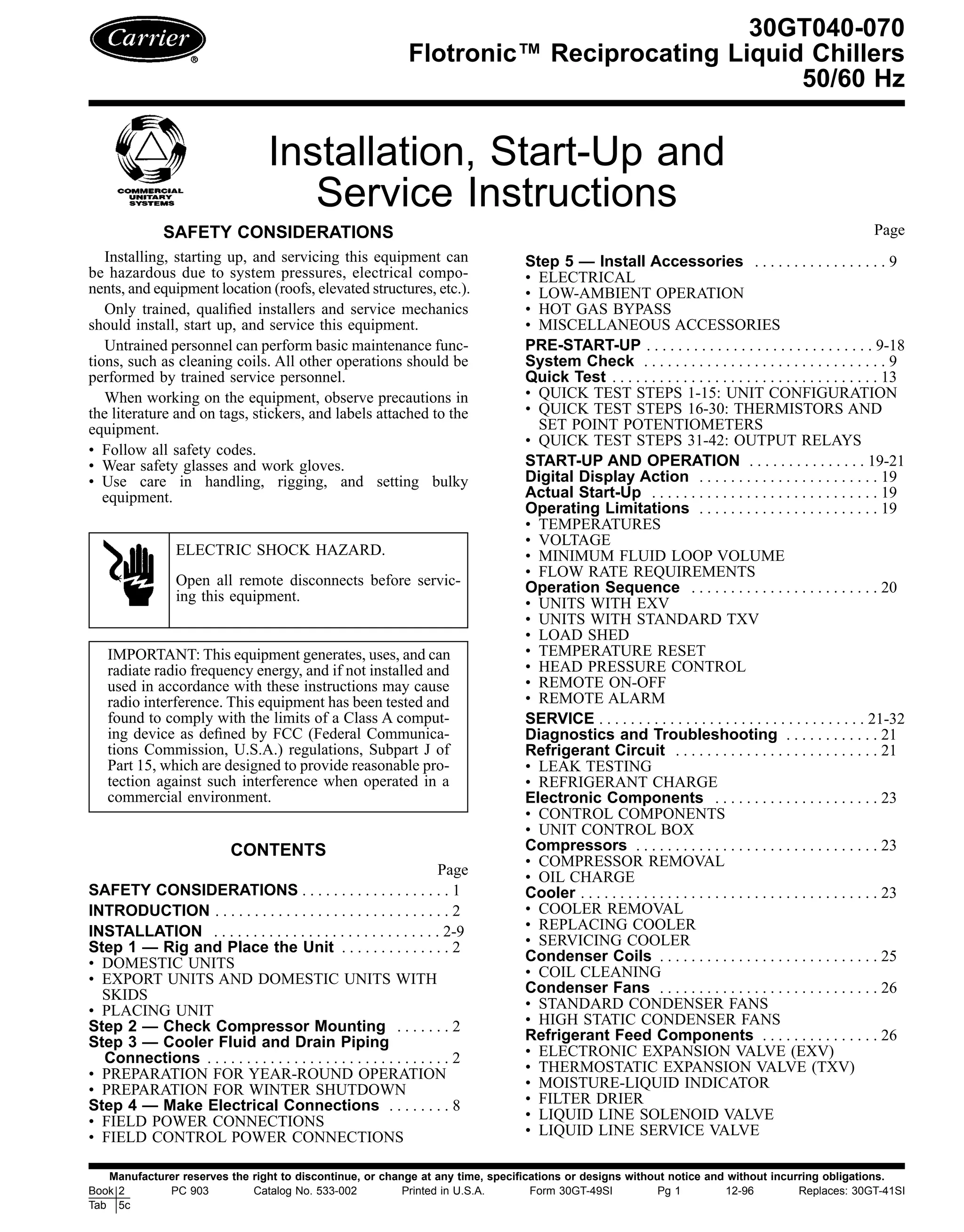
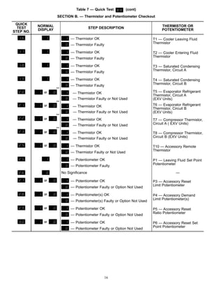
C — Copper Fins, Copper Tubing
Mtg — Mounting
NOTES:
1. Unit must have clearances for airflow as follows:
TOP — Do not restrict in any way.
ENDS — [1524] 5 ft
SIDES — [1829] 6 ft
2. 2.00Љ dia holes are recommended for parallel conductors on 040 and 045
(208/230 V) units.
3. 35⁄8Љ dia hole is recommended for single entry power on 050 (208/230 V)
units.
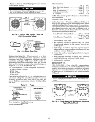
4. Mounting holes may be used to mount unit to concrete pad. They are not
recommended for spring isolator location.
5. If spring isolators are used, a perimeter support channel between the unit
and the isolators is recommended.
6. Dimensions in [ ] are millimeters.
7. Thru-the-door handles for non-fused disconnect option on 380/415 v and
460 v units only. When unit has non-fused disconnect option, power-side
door opens from right side, NOT left side as shown for standard units.
UNIT 30GT
DIMENSIONS
‘‘A’’ ‘‘B’’ ‘‘C’’ ‘‘D’’
040 3Ј-511⁄16Љ
[1059]
3Ј-1013⁄16Љ
[1189]
4Ј-51⁄2Љ
[1359]
1Ј-111⁄8Љ
[587.5]
040C 3Ј-57⁄8Љ
[1064]
3Ј-11Љ
[1194]
4Ј-51⁄2Љ
[1359]
1Ј-111⁄8Љ
[587.5]
045 3Ј-61⁄16Љ
[1069]
3Ј-1013⁄16Љ
[1189]
5Ј-51⁄2Љ
[1663]
1Ј-53⁄16Љ
[436.6]
045C 3Ј-63⁄16Љ
[1072]
3Ј-11Љ
[1194]
5Ј-51⁄2Љ
[1663]
1Ј-53⁄16Љ
[436.6]
050 3Ј-57⁄8Љ
[1064]
3Ј-11Љ
[1194]
5Ј-51⁄2Љ
[1663]
1Ј-53⁄16Љ
[436.6]
050C
3Ј-6Љ
[1067]
3Ј-113⁄16Љ
[1199]
5Ј-51⁄2Љ
[1663]
1Ј-53⁄16Љ
[436.6]
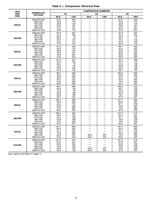
Fig. 1 — Dimensions, 30GT040-050
FIELD POWER SUPPLY CONNECTIONS
Unit 30GT Voltage Hz Diameter Qty
040,045 208/230 60
35⁄8Љ
[92.0] 1
050 208/230 60
21⁄2Љ
[63.5]
2
040-050 460 60
21⁄2Љ
[63.5]
1
040-050 575 60
21⁄2Љ
[63.5] 1
040-050 380 60
21⁄2Љ
[63.5] 1
040,045 346 50 21⁄2Љ
[63.5] 1
050 346 50 35⁄8Љ
[92.0]
1
040,045 380/415 50
21⁄2Љ
[63.5] 1
050 380/415 50 35⁄8Љ
[92.0] 1
3](https://image.slidesharecdn.com/30gt040-070carrierflotronic-150907010846-lva1-app6892/85/30-gt040-070-carrier-flotronic-3-320.jpg)
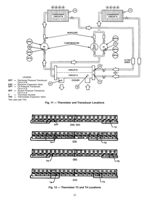
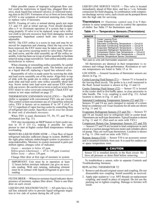
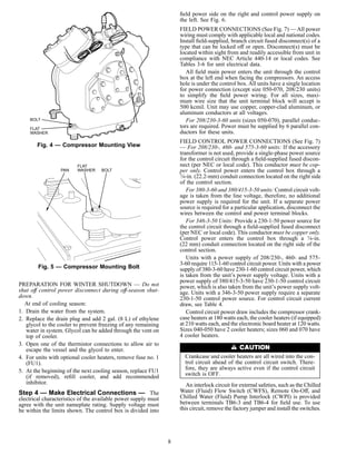
![LEGEND
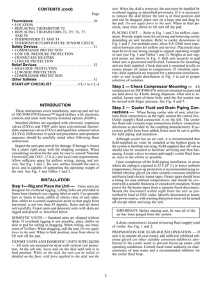
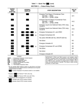
C — Copper Fins, Copper Tubing
Mtg — Mounting
NOTES:
1. Dimensions in [ ] are millimeters.
2. Unit must have clearances for airflow as follows:
TOP — Do not restrict in any way.
ENDS — [1524] 5 ft
SIDES — [1829] 6 ft
3. Mounting holes may be used to mount unit to concrete pad. They are not
recommended for spring isolator location.
4. If spring isolators are used, a perimeter support channel between the unit
and the isolators is recommended.
5. Thru-the-door handles for non-fused disconnect option on 380/415 v and
460 v units only. When unit has non-fused disconnect option, power-side
door opens from right side, NOT left side as shown for standard units.
UNIT 30GT
DIMENSIONS
‘‘A’’ ‘‘B’’
060
3Ј-67⁄8Љ
[1090]
4Ј-105⁄16Љ
[1481]
060C
3Ј-7Љ
[1092]
4Ј-109⁄16Љ
[1488]
070
3Ј-6Љ
[1067]
4Ј-101⁄2Љ
[1486]
070C 3Ј-63⁄16Љ
[1072]
4Ј-107⁄8Љ
[1496]
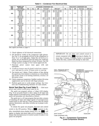
Fig. 2 − Dimensions, 30GT060,070
FIELD POWER SUPPLY CONNECTIONS
Unit 30GT Voltage Hz Diameter Qty
060 208/230 60
21⁄2Љ
[63.5] 2
070 208/230 60
35⁄8Љ
[92.0]
2
060 460 60
21⁄2Љ
[63.5]
1
070 460 60
35⁄8Љ
[92.0] 1
060,070 575 60 21⁄2Љ
[63.5] 1
060,070 380 60 35⁄8Љ
[92.0]
1
060,070 346 50 35⁄8Љ
[92.0]
1
060,070 380/415 50
35⁄8Љ
[92.0]
1
4](https://image.slidesharecdn.com/30gt040-070carrierflotronic-150907010846-lva1-app6892/85/30-gt040-070-carrier-flotronic-4-320.jpg)
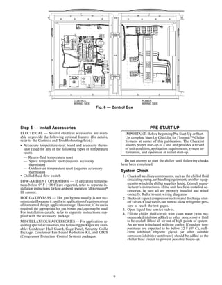
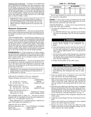
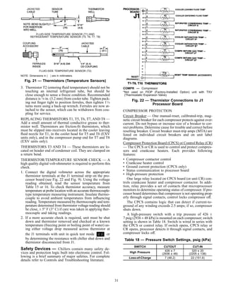
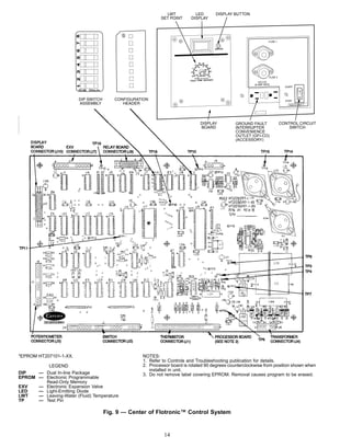
![LEGEND
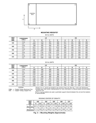
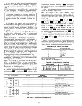
A — Alarm
CWFS — Chilled Water (Fluid) Flow
Switch
CWPI — Chilled Water (Fluid) Pump
Interlock
GND — Ground
NEC — National Electrical Code, U.S.A.
O.A. — Outdoor Air
TB — Terminal Block
Field Power Wiring
Field Control Wiring
Factory Installed Wiring
NOTES:
1. Factory wiring is in accordance with NEC. Field modifica-
tions or additions must be in compliance with all applicable
codes.
2. Wiring for main field power supply must be rated 75 C mini-
mum. Use copper, copper-clad aluminum, or aluminum con-
ductors for all units.
3. Power for control circuit should be supplied from a separate
source through a field-supplied fused disconnect with 30 amp
maximum protection for 115-v control circuits, 15 amp maxi-
mum protection for 230-v control circuit for a unit with cooler
heaters, and 5 amp maximum for a unit without cooler heat-
ers. Connect control circuit power to terminals 1 and 2 of
TB4. Connect neutral side of supply to terminal 2 of TB4.
Control circuit conductors for all units must be copper only.
4. Terminals 3 and 4 of TB6 are for field connection of remote
ON-OFF control, CWPI, and CWFS. The contacts must be
rated for dry circuit application capable of reliably switching
a 5 vdc, .5 mA. load. Remove jumper between 3 and 4 of
TB6 if remote ON-OFF is installed.
5. The maximum load allowed for the remote alarm circuit is
75 va sealed, 360 va inrush at 115 or 230 v, depending on
model. Remove resistor across terminals 1 and 2 of TB5
when using remote alarm.
6. Dimensions in [ ] are millimeters.
Fig. 7 — Field Wiring
10](https://image.slidesharecdn.com/30gt040-070carrierflotronic-150907010846-lva1-app6892/85/30-gt040-070-carrier-flotronic-10-320.jpg)
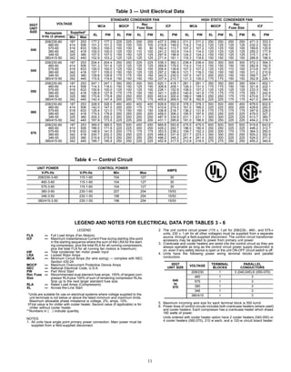
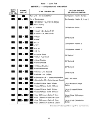
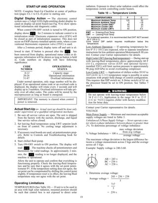
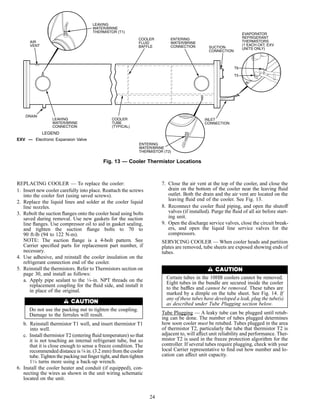
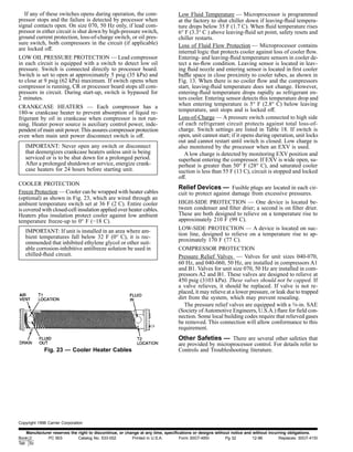
![2. Determine maximum deviation from average voltage:
(AB) 243 - 239 = 4 v
(BC) 239 - 236 = 3 v
(AC) 239 - 238 = 1 v
Maximum deviation is 4 v.
3. Determine % voltage imbalance:
4
% Voltage Imbalance = 100 x
239
= 1.7%
This voltage imbalance is satisfactory as it is below the
maximum allowable of 2%.
IMPORTANT: If the supply voltage phase imbalance
is more than 2%, contact your local electric utility com-
pany immediately. Do not operate unit until imbalance
condition is corrected.
Control Circuit Power— Electronic control includes logic to
detect low control circuit voltage. Acceptable voltage range
is shown in Table 4.
MINIMUM FLUID LOOP VOLUME — To obtain proper
temperature control, loop fluid volume must be at least
3 gallons per ton (3.25 L per kW) of chiller nominal capac-
ity for air conditioning and at least 6 gallons per ton (6.5 L
per kW) for process applications or systems that must op-
erate in low ambients (below 32 F [0° C]). Refer to appli-
cation information in Product Data literature for details.
FLOW RATE REQUIREMENTS — Standard chillers should
be applied with nominal flow rates approximating those listed
in Table 11. Higher or lower flow rates are permissible to
obtain lower or higher temperature rises. Minimum flow rates
must be exceeded to assure turbulent flow and proper heat
transfer in the cooler.
Operation below minimum flow could subject tubes to
frost pinching in tube sheet, resulting in failure of cooler.
Consult application data and job design requirements to
determine flow rate requirements for particular installation.
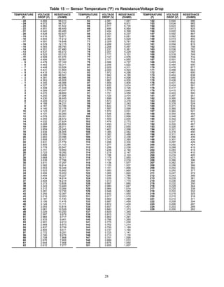
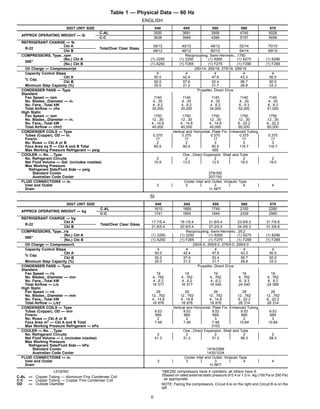
Table 11 — Nominal and Minimum Cooler
Fluid Flow Rates
30GT
UNIT
SIZE
NOMINAL FLOW
RATE*
MINIMUM FLOW
RATE (See Notes)
Gpm L/s Gpm L/s
040 86 5.43 36.8 2.38
045 101 6.37 37.7 2.38
050 123 7.76 37.7 2.38
060 151 9.53 47.5 3.00
070 173 10.91 47.5 3.00
LEGEND
ARI — Air Conditioning and Refrigeration Institute (U.S.A.)
N — Liters per kW
V — Gallons per ton
*Nominal flow rates required at ARI conditions 44 F (7 C) leaving-
fluid temperature, 54 F (12 C) entering-fluid temperature, 95 F (35 C)
ambient. Fouling factor .00025 ft2
• hr • F/Btu (.000044 m2
• K/W).
NOTES:
1. Minimum flow based on 1.0 fps (0.30 m/s) velocity in cooler with-
out special cooler baffling.
2. Minimum Loop Volumes:
Gallons = V x ARI Cap. (tons)
Liters = N x ARI Cap. (kW)
APPLICATION V N
Normal Air Conditioning 3 3.25
Process Type Cooling 6 to 10 6.5 to 10.8
Low Ambient Unit Operation 6 to 10 6.5 to 10.8
Operation Sequence — During unit off cycle, crank-
case heaters are energized. If ambient temperature is below
36 F (2 C), cooler heaters and a microprocessor board heater
are also energized.
When control ON-OFF switch is turned to ON position,
control first goes through a 2-minute initialization period,
during which the display continuously shows .
Ninety (90) seconds after leaves display, control
begins to bring on compressors. Rate at which compressors
are started depends on leaving chilled fluid temperature and
rate of change of leaving-fluid temperature.
On all units, an automatic lead-lag feature in control sys-
tem determines by random selection either circuit A or B to
start first.
At first call for cooling, microprocessor starts first com-
pressor, deenergizes crankcase heater, and starts one con-
denser fan.
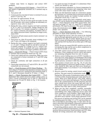
UNITS WITH EXV — The EXV remains closed for 10 sec-
onds to purge cooler and suction line of any liquid refrig-
erant that may have migrated to these areas during off pe-
riod. After 10 seconds, EXV starts to open. As more cooling
is required, control brings on additional stages of capacity.
Loading sequence for compressors is shown in Table 12.
Lag compressor will shut down, and lead compressor will
continue to run.After lag compressor has shut down, the EXV
is signaled to close. Lead compressor remains on until EXV
is less than 600 steps open, and either the saturated suction
temperature is less than 25 F (−4 C) as sensed by thermistor
T5 or T6, or one minute has elapsed.
UNITS WITH STANDARD TXV — Liquid line solenoid
valve is not energized for first 10 seconds of compressor op-
eration. This is called pumpout cycle.
Microprocessor determines how rapidly capacity stages are
added or subtracted, based on deviation from leaving chilled
fluid temperature set point and rate of change of leaving-
fluid temperature. If fluid temperature is very warm and pull-
down option is being used, microprocessor limits rate of
temperature drop of leaving fluid to 1° F (0.56° C) per minute
to avoid high peak kW charges. If the capacity is being lim-
ited by pulldown, the control display shows when
the display button is pressed. Once capacity has been sat-
isfied, the unit starts to shut down.
Lag compressor will be shut down and lead compressor
continues to run for 10 seconds to purge cooler of any
refrigerant.
LOAD SHED — If load shed option is being used, control
limits maximum capacity to load shed input value. Refer to
Controls and Troubleshooting publication for details. If ca-
pacity is limited by a load shed signal, display shows
when display button is pressed.
TEMPERATURE RESET — If temperature reset is being
used, microprocessor adjusts leaving-fluid temperature to ob-
tain greater part-load efficiency. Refer to Controls and Trouble-
shooting book for details. If leaving-fluid temperature is
being reset, display shows when the display button
is pressed.
HEAD PRESSURE CONTROL
Units with EXV — Microprocessor also controls EXV to main-
tain a superheat of 24° to 30° F (13.3° to 16.7° C) entering
compressor cylinders.
20](https://image.slidesharecdn.com/30gt040-070carrierflotronic-150907010846-lva1-app6892/85/30-gt040-070-carrier-flotronic-20-320.jpg)