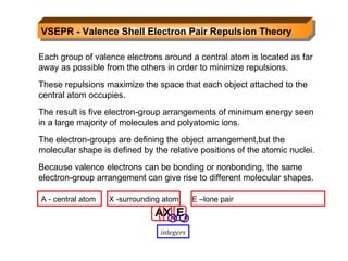
A very basic look at the dative covalent bond. It is normally met at CAPE, but recently has been introduced to students in form three. It is that form three occurrence which really prompted this piece of work
This is a report about Aldehydes. The content of this slideshow are as follows: What is an aldehyde, How to name aldehydes with IUPAC Nomenclature and Common Names, The Physical Properties of Aldehydes, and the examples of aldehyde and its uses. The main objective of this report is to widen the knowledge of the readers/learners concerning of the stated topic so that they can further understand the concept of aldehydes.
Report made by: Students of Sogod National High School STEM 9-Newton
Kyla Krystelle Salva
Krishia Belle Cambalon
Marycris Felicilda
In organic chemistry, an alkyne is an unsaturated hydrocarbon containing at least one carbon—carbon triple bond. The simplest acyclic alkynes with only one triple bond and no other functional groups form a homologous series with the general chemical formula CₙH₂ₙ−2
Kubernetes & AI - Beauty and the Beast !?! @KCD Istanbul 2024Tobias Schneck
As AI technology is pushing into IT I was wondering myself, as an “infrastructure container kubernetes guy”, how get this fancy AI technology get managed from an infrastructure operational view? Is it possible to apply our lovely cloud native principals as well? What benefit’s both technologies could bring to each other?
Let me take this questions and provide you a short journey through existing deployment models and use cases for AI software. On practical examples, we discuss what cloud/on-premise strategy we may need for applying it to our own infrastructure to get it to work from an enterprise perspective. I want to give an overview about infrastructure requirements and technologies, what could be beneficial or limiting your AI use cases in an enterprise environment. An interactive Demo will give you some insides, what approaches I got already working for real.
Encryption in Microsoft 365 - ExpertsLive Netherlands 2024Albert Hoitingh
In this session I delve into the encryption technology used in Microsoft 365 and Microsoft Purview. Including the concepts of Customer Key and Double Key Encryption.
UiPath Test Automation using UiPath Test Suite series, part 4DianaGray10
Welcome to UiPath Test Automation using UiPath Test Suite series part 4. In this session, we will cover Test Manager overview along with SAP heatmap.
The UiPath Test Manager overview with SAP heatmap webinar offers a concise yet comprehensive exploration of the role of a Test Manager within SAP environments, coupled with the utilization of heatmaps for effective testing strategies.
Participants will gain insights into the responsibilities, challenges, and best practices associated with test management in SAP projects. Additionally, the webinar delves into the significance of heatmaps as a visual aid for identifying testing priorities, areas of risk, and resource allocation within SAP landscapes. Through this session, attendees can expect to enhance their understanding of test management principles while learning practical approaches to optimize testing processes in SAP environments using heatmap visualization techniques
What will you get from this session?
1. Insights into SAP testing best practices
2. Heatmap utilization for testing
3. Optimization of testing processes
4. Demo
Topics covered:
Execution from the test manager
Orchestrator execution result
Defect reporting
SAP heatmap example with demo
Speaker:
Deepak Rai, Automation Practice Lead, Boundaryless Group and UiPath MVP
The Art of the Pitch: WordPress Relationships and SalesLaura Byrne
Clients don’t know what they don’t know. What web solutions are right for them? How does WordPress come into the picture? How do you make sure you understand scope and timeline? What do you do if sometime changes?
All these questions and more will be explored as we talk about matching clients’ needs with what your agency offers without pulling teeth or pulling your hair out. Practical tips, and strategies for successful relationship building that leads to closing the deal.
Essentials of Automations: Optimizing FME Workflows with ParametersSafe Software
Are you looking to streamline your workflows and boost your projects’ efficiency? Do you find yourself searching for ways to add flexibility and control over your FME workflows? If so, you’re in the right place.
Join us for an insightful dive into the world of FME parameters, a critical element in optimizing workflow efficiency. This webinar marks the beginning of our three-part “Essentials of Automation” series. This first webinar is designed to equip you with the knowledge and skills to utilize parameters effectively: enhancing the flexibility, maintainability, and user control of your FME projects.
Here’s what you’ll gain:
- Essentials of FME Parameters: Understand the pivotal role of parameters, including Reader/Writer, Transformer, User, and FME Flow categories. Discover how they are the key to unlocking automation and optimization within your workflows.
- Practical Applications in FME Form: Delve into key user parameter types including choice, connections, and file URLs. Allow users to control how a workflow runs, making your workflows more reusable. Learn to import values and deliver the best user experience for your workflows while enhancing accuracy.
- Optimization Strategies in FME Flow: Explore the creation and strategic deployment of parameters in FME Flow, including the use of deployment and geometry parameters, to maximize workflow efficiency.
- Pro Tips for Success: Gain insights on parameterizing connections and leveraging new features like Conditional Visibility for clarity and simplicity.
We’ll wrap up with a glimpse into future webinars, followed by a Q&A session to address your specific questions surrounding this topic.
Don’t miss this opportunity to elevate your FME expertise and drive your projects to new heights of efficiency.
GraphRAG is All You need? LLM & Knowledge GraphGuy Korland
Guy Korland, CEO and Co-founder of FalkorDB, will review two articles on the integration of language models with knowledge graphs.
1. Unifying Large Language Models and Knowledge Graphs: A Roadmap.
https://arxiv.org/abs/2306.08302
2. Microsoft Research's GraphRAG paper and a review paper on various uses of knowledge graphs:
https://www.microsoft.com/en-us/research/blog/graphrag-unlocking-llm-discovery-on-narrative-private-data/
DevOps and Testing slides at DASA ConnectKari Kakkonen
My and Rik Marselis slides at 30.5.2024 DASA Connect conference. We discuss about what is testing, then what is agile testing and finally what is Testing in DevOps. Finally we had lovely workshop with the participants trying to find out different ways to think about quality and testing in different parts of the DevOps infinity loop.
Neuro-symbolic is not enough, we need neuro-*semantic*Frank van Harmelen
Neuro-symbolic (NeSy) AI is on the rise. However, simply machine learning on just any symbolic structure is not sufficient to really harvest the gains of NeSy. These will only be gained when the symbolic structures have an actual semantics. I give an operational definition of semantics as “predictable inference”.
All of this illustrated with link prediction over knowledge graphs, but the argument is general.
Builder.ai Founder Sachin Dev Duggal's Strategic Approach to Create an Innova...Ramesh Iyer
In today's fast-changing business world, Companies that adapt and embrace new ideas often need help to keep up with the competition. However, fostering a culture of innovation takes much work. It takes vision, leadership and willingness to take risks in the right proportion. Sachin Dev Duggal, co-founder of Builder.ai, has perfected the art of this balance, creating a company culture where creativity and growth are nurtured at each stage.
State of ICS and IoT Cyber Threat Landscape Report 2024 previewPrayukth K V
The IoT and OT threat landscape report has been prepared by the Threat Research Team at Sectrio using data from Sectrio, cyber threat intelligence farming facilities spread across over 85 cities around the world. In addition, Sectrio also runs AI-based advanced threat and payload engagement facilities that serve as sinks to attract and engage sophisticated threat actors, and newer malware including new variants and latent threats that are at an earlier stage of development.
The latest edition of the OT/ICS and IoT security Threat Landscape Report 2024 also covers:
State of global ICS asset and network exposure
Sectoral targets and attacks as well as the cost of ransom
Global APT activity, AI usage, actor and tactic profiles, and implications
Rise in volumes of AI-powered cyberattacks
Major cyber events in 2024
Malware and malicious payload trends
Cyberattack types and targets
Vulnerability exploit attempts on CVEs
Attacks on counties – USA
Expansion of bot farms – how, where, and why
In-depth analysis of the cyber threat landscape across North America, South America, Europe, APAC, and the Middle East
Why are attacks on smart factories rising?
Cyber risk predictions
Axis of attacks – Europe
Systemic attacks in the Middle East
Download the full report from here:
https://sectrio.com/resources/ot-threat-landscape-reports/sectrio-releases-ot-ics-and-iot-security-threat-landscape-report-2024/
State of ICS and IoT Cyber Threat Landscape Report 2024 preview
Chemical bonding part 2
1. VSEPR - Valence Shell Electron Pair Repulsion Theory Each group of valence electrons around a central atom is located as far away as possible from the others in order to minimize repulsions. These repulsions maximize the space that each object attached to the central atom occupies. The result is five electron-group arrangements of minimum energy seen in a large majority of molecules and polyatomic ions. The electron-groups are defining the object arrangement,but the molecular shape is defined by the relative positions of the atomic nuclei. Because valence electrons can be bonding or nonbonding, the same electron-group arrangement can give rise to different molecular shapes. AX m E n A - central atom X -surrounding atom E –lone pair integers
2. Factors Affecting Actual Bond Angles Bond angles are consistent with theoretical angles when the atoms attached to the central atom are the same and when all electrons are bonding electrons of the same order. ideal 120 0 120 0 larger EN greater electron density Lone pairs repel bonding pairs more strongly than bonding pairs repel each other. 95 0 122 0 116 0 real Effect of Double Bonds Effect of Nonbonding(Lone) Pairs
3.
4. Figure 10.2 the five basic molecular shapes linear trigonal planar tetrahedral trigonal bipyramidal octahedral
5. Figure 10.3 The single molecular shape of the linear electron-group arrangement. Examples: CS 2 , HCN, BeF 2
6. Figure 10.4 The two molecular shapes of the trigonal planar electron-group arrangement. Examples: SO 3 , BF 3 , NO 3 - , CO 3 2- Examples: SO 2 , O 3 , PbCl 2 , SnBr 2 Class Shape
7. Figure 10.5 The three molecular shapes of the tetrahedral electron-group arrangement. Examples: CH 4 , SiCl 4 , SO 4 2- , ClO 4 - NH 3 PF 3 ClO 3 H 3 O + H 2 O OF 2 SCl 2
9. Figure 10.7 The four molecular shapes of the trigonal bipyramidal electron-group arrangement. SF 4 XeO 2 F 2 I F 4 + I O 2 F 2 - ClF 3 BrF 3 XeF 2 I 3 - I F 2 - PF 5 AsF 5 SOF 4
10. Figure 10.8 The three molecular shapes of the octahedral electron-group arrangement. SF 6 I OF 5 BrF 5 TeF 5 - XeOF 4 XeF 4 I Cl 4 -
11. Figure 10.9 A summary of common molecular shapes with two to six electron groups.
12. Figure 10.10 The steps in determining a molecular shape. Molecular formula Lewis structure Electron domain geometry Bond angles Molecular shape (AX m E n ) Electron domain geometry =No. of atoms attached + no. of lone pairs 2- linear 3- trigonalpyramidal 4- tetrahedral 5- trigonal bipyramidal 6- octahedral Step 1 Step 2 Step 3 Step 4
13. SAMPLE PROBLEM 10.6 Predicting Molecular Shapes with Two, Three, or Four Electron Groups Electron domain geometry : tetrahedral bond angle: 109.5 0 Molecular geometry: trigonal pyramidal . The type of shape is AX 3 E PROBLEM: Draw the molecular shape and predict the bond angles (relative to the ideal bond angles) of (a) PF 3 and (b) COCl 2 . SOLUTION: (a) For PF 3 - there are 26 valence electrons, 1 nonbonding pair
14. SAMPLE PROBLEM 10.6 Predicting Molecular Shapes with Two, Three, or Four Electron Groups continued (b) For COCl 2 , C has the lowest EN and will be the center atom. There are 24 valence e - , 3 atoms attached to the center atom. Electron domain geometry: trigonal planar Type : AX 3 Molecular geometry: trigonal planar bond angle= 120 0 124.5 0 111 0
15.
16. (b) BrF 5 - 42 valence e - ; 5 bonding pairs and 1 nonbonding pair on central atom. Electron domain geometry : octahedral Molecular geometry shape is AX 5 E, square pyramidal. Bond angles : 90
17. Figure 10.12 The orientation of polar molecules in an electric field. Electric field OFF Electric field ON
18.
19. SAMPLE PROBLEM 10.9 Predicting the Polarity of Molecules (a) Ammonia, NH 3 (b) Boron trifluoride, BF 3 (c) Carbonyl sulfide, COS (atom sequence SCO) bond dipoles molecular dipole The dipoles reinforce each other, so the overall molecule is definitely polar . PROBLEM: predict whether each of the following molecules is polar and show the direction of bond dipoles and the overall molecular dipole when applicable: PLAN: Draw the shape, and combine the concepts to determine the polarity. SOLUTION: (a) NH 3
20. SAMPLE PROBLEM 10.10 Predicting the Polarity of Molecules continued (b) BF 3 has 24 valence e - and all electrons around the B will be involved in bonds. The shape is AX 3 , trigonal planar. F (EN 4.0) is more electronegative than B (EN 2.0) and all of the dipoles will be directed from B to F. Because all are at the same angle and of the same magnitude, the molecule is nonpolar. 120 0 (c) COS is linear. C and S have the same EN (2.0) but Oxygen is more electronegative and the molecule is quite polar(DEN) so the molecule is polar overall.
21. SAMPLE PROBLEM Combined Concepts Electron domain geometry : trigonal planar Molecular geometry : AX 2 E - bent Bond angles : 120 Lewis Structure Formal charge of the central atom: -1 Hybridization of the central atom: sp 2 Polarity : polar PROBLEM: (a) SnCl 2 SOLUTION: 18 valence e - ;
22. SAMPLE PROBLEM Combined Concepts Electron domain geometry : linear Molecular geometry : AX 2 - linear Bond angles : 180 Lewis Structure Formal charge of the C: 0 Hybridization of the C: sp Polarity : nonpolar PROBLEM: (b) C 2 H 2 SOLUTION: 10 valence e - ; all electrons around central atom will be in bonding pairs;
23. The Central Themes of MO Theory A molecule is viewed on a quantum mechanical level as a collection of nuclei surrounded by delocalized molecular orbitals . Atomic wave functions are summed to obtain molecular wave functions. If wave functions reinforce each other, a bonding MO is formed (region of high electron density exists between the nuclei). If wave functions cancel each other, an antibonding MO is formed (a node of zero electron density occurs between the nuclei).
24. Properties of Molecular orbitals *holds maximum of 2 electrons of opposite spins *have definite/discrete energy states *electron density distribution can be represented by contour diagrams (similar to AO’s – s, p, d, f) *MO is associated with the entire molecule *MO’s are formed by the linear combination of atomic orbitals (AO’s) and the overlap results in the formation of sigma ( ) and pi ( ) bonds
25. Figure 11.14 Contours and energies of the bonding and antibonding molecular orbitals (MOs) in H 2 . The bonding MO is lower in energy and the antibonding MO is higher in energy than the AOs that combined to form them.
26. Bond Order = ½ (bonding electrons – nonbonding electrons)
27. Figure 11.15 The MO diagram for H 2 . Energy MO of H 2 * 1s 1s H 2 bond order = 1/2 (2-0) = 1 Filling molecular orbitals with electrons follows the same concept as filling atomic orbitals. AO of H 1s AO of H 1s
28. Figure 11.16 MO diagram for He 2 + and He 2 . Energy MO of He + * 1s 1s MO of He 2 He 2 + bond order = 1/2 He 2 bond order = 0 AO of He + 1s AO of He 1s AO of He 1s * 1s 1s Energy AO of He 1s
29. SAMPLE PROBLEM 11.3 Predicting Stability of Species Using MO Diagrams SOLUTION: MO of H 2 + bond order = 1/2(1-0) = 1/2 H 2 + does exist MO of H 2 - bond order = 1/2(2-1) = 1/2 H 2 - does exist configuration is ( 1s ) 2 ( 2s ) 1 PROBLEM: Use MO diagrams to predict whether H 2 + and H 2 - exist. Determine their bond orders and electron configurations. PLAN: Use H 2 as a model and accommodate the number of electrons in bonding and antibonding orbitals. Find the bond order. 1s AO of H 1s AO of H + 1s 1s AO of H AO of H - configuration is ( 1s ) 1
30. Figure 11.18 Li 2 bond order = 1 Be 2 bond order = 0 Bonding in s-block homonuclear diatomic molecules. Energy Li 2 Be 2 * 2s 2s 2s 2s 2s 2s * 2s 2s
31. Figure 11.19 Contours and energies of s and p MOs through combinations of 2p atomic orbitals.
32. Figure 11.20 Relative MO energy levels for Period 2 homonuclear diatomic molecules. MO energy levels for O 2 , F 2 , and Ne 2 MO energy levels for B 2 , C 2 , and N 2 without 2s-2p mixing with 2s-2p mixing
33. Figure 11.21 MO occupancy and molecular properties for B 2 through Ne 2
34. SAMPLE PROBLEM 11.4 Using MO Theory to Explain Bond Properties SOLUTION: Explain these facts with diagrams that show the sequence and occupancy of MOs. N 2 has 10 valence electrons, so N 2 + has 9. O 2 has 12 valence electrons, so O 2 + has 11. PROBLEM: As the following data show, removing an electron from N 2 forms an ion with a weaker, longer bond than in the parent molecules, whereas the ion formed from O 2 has a stronger, shorter bond: PLAN: Find the number of valence electrons for each species, draw the MO diagrams, calculate bond orders, and then compare the results. Bond energy (kJ/mol) Bond length (pm) N 2 N 2 + O 2 O 2 + 945 110 498 841 623 112 121 112
35. SAMPLE PROBLEM 11.4 Using MO Theory to Explain Bond Properties continued 2s 2s 2p 2p 2p 2p N 2 N 2 + O 2 O 2 + bond orders 1/2(8-2)=3 1/2(7-2)=2.5 1/2(8-4)=2 1/2(8-3)=2.5 bonding e - lost antibonding e - lost 2s 2s 2p 2p 2p 2p
36. Energy MO of HF Figure 11.23 The MO diagram for HF AO of H 1s 2p x 2p y AO of F 2p
37. Energy Figure 11.24 The MO diagram for NO MO of NO possible Lewis structures 2s AO of N 2p * 1s 1s 2s AO of O 2p 2p 2p * 2p * 2s
38.
39. a. O 2 2- 1. Molecular orbital diagram: 2s 2 * 2s 2 2p 4 2p 2 * 2p 4 2.Electronic configuration using MO: 3.Bond order = ½(8-6) = 1
40. b. N 2 1. Molecular orbital diagram: 2s 2 * 2s 2 2p 4 2p 2 2.Electronic configuration using MO: 3.Bond order = ½(8-2) = 3
42. Figure 10.1 The steps in converting a molecular formula into a Lewis structure. Molecular formula Atom placement Sum of valence e - Remaining valence e - Lewis structure Place atom with lowest EN in center Add A-group numbers Draw single bonds. Subtract 2e - for each bond. Give each atom 8e - (2e - for H) Step 1 Step 2 Step 3 Step 4
43. Figure 10.12 The steps in determining a molecular shape. Molecular formula Lewis structure Electron-group arrangement Bond angles Molecular shape (AX m E n ) Count all e - groups around central atom (A) Note lone pairs and double bonds Count bonding and nonbonding e - groups separately. Step 1 Step 2 Step 3 Step 4 See Figure 10.1
45. Metallic Bond – bonding in which bonding electrons are relatively free to move throughout the three-dimensional structure. Physical Properties of Metals *Metal surfaces has a characteristic luster *Metals have high electrical conductivity *Metals have high thermal/heat conductivity *Most metals are malleable and ductile
46. Electron Sea Model for Metallic Bonding *in this model, the metal is pictured as an array of metal cations in a “sea” of electrons. *electrons are confined to the metal by electrostatic attractions to the cations, and they are uniformly distributed throughout the structure. *above physical properties of metal can be explained by this model
47. Molecular-Orbital Model for Metals or Band Theory *in a metal the number of atomic orbitals that interact or overlap is very large thus, the number of molecular orbitals is also very large. *it has an energy band – numerous and continuous tiny energy separation of between metal orbitals. *electrons available for metallic bonding do not completely fill the available molecular orbitals. It is partially filled. *electrons at the top require a little input to be promoted to still higher energy orbitals.
48. Metallic conductors have partially filled energy bands, as shown in (a). Insulators have filled and empty energy bands, as in (b). Notes: According to the MO theory metals are able to conduct electricity because there are more molecular orbitals in the band than are necessary to accommodate the bonding electrons. In metals an excited electron may easily move to a nearby higher orbital. The bonding and antibonding molecular orbitals of insulators such as diamond are separated by a large energy gap so there are no nearby orbitals for the electrons to move to, making diamond a poor conductor of electricity.