Download as PDF, PPTX


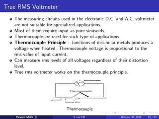
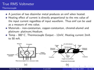


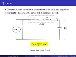


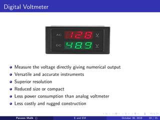


This document discusses various types of electronic measurement instruments. It begins by explaining the limitations of traditional electrical voltmeters and ammeters that electronic instruments aim to overcome, such as having high input impedance and ability to measure low voltages. It then describes different circuits for D.C. and A.C. voltmeters using transistors and op-amps. True RMS voltmeters which can measure distorted waveforms using a thermocouple principle are also covered. Q-meters which measure coil and capacitor characteristics using a series RLC resonant circuit are explained. Finally, digital voltmeters which directly provide a numerical output through analog to digital conversion are summarized.


