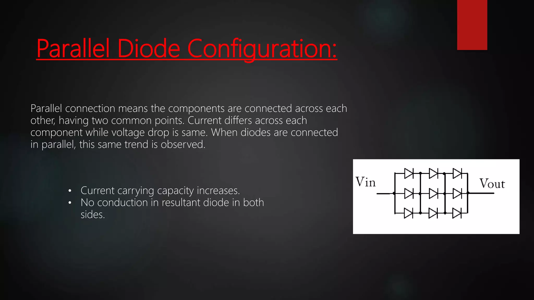
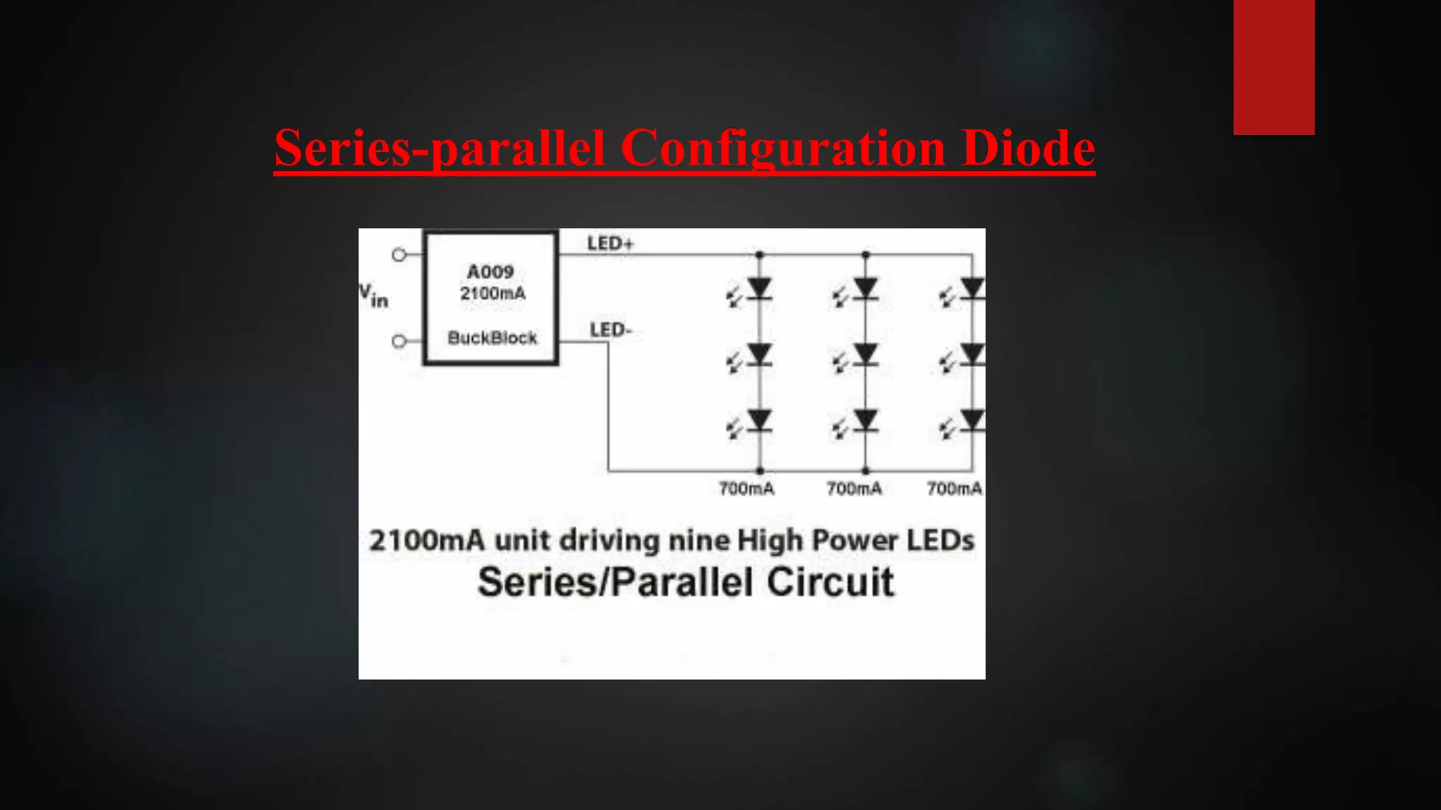
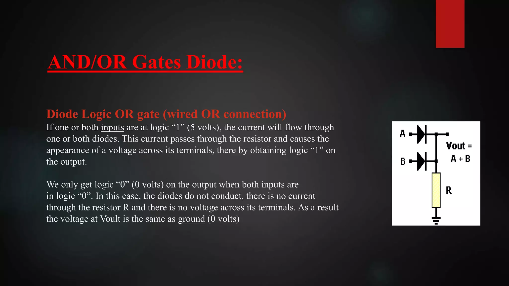
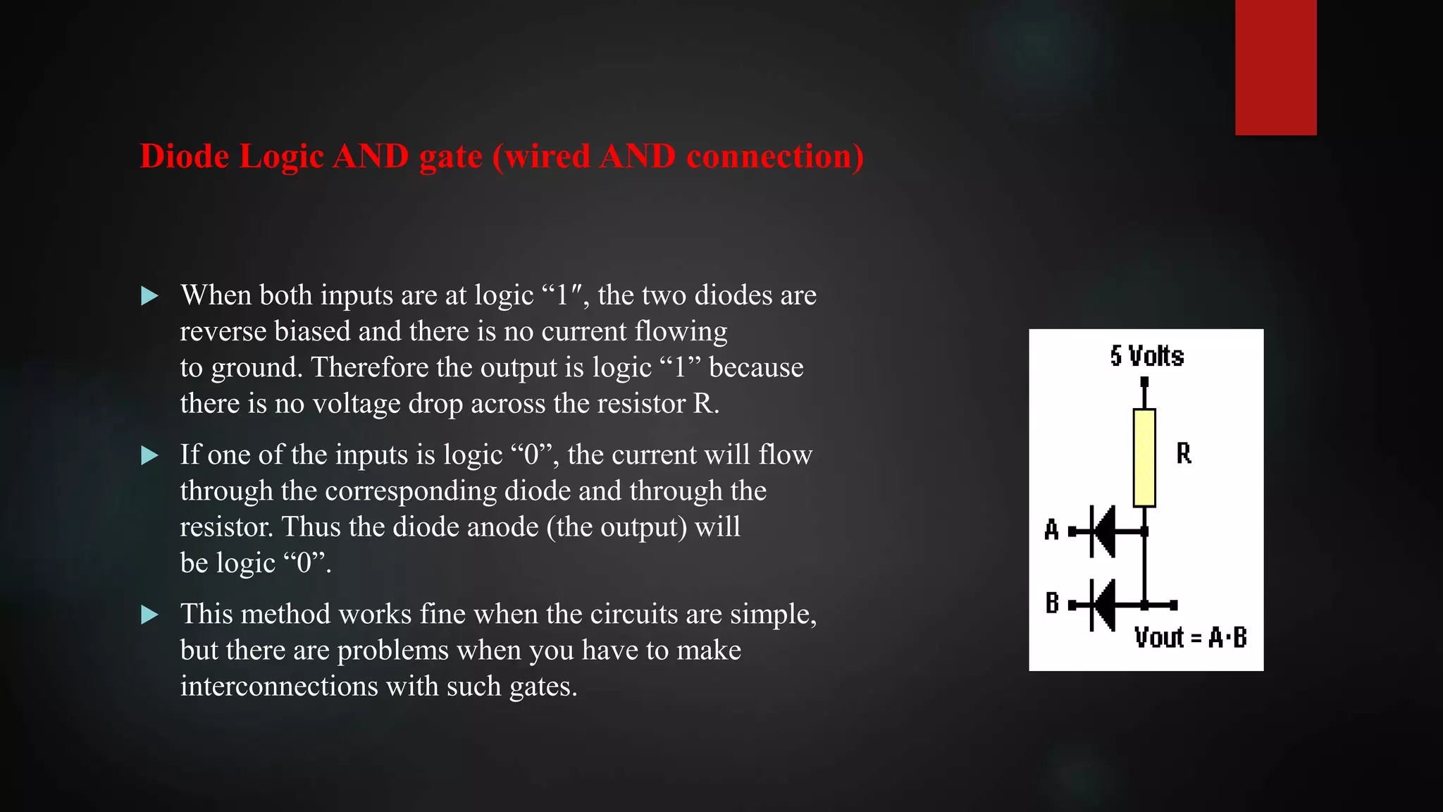
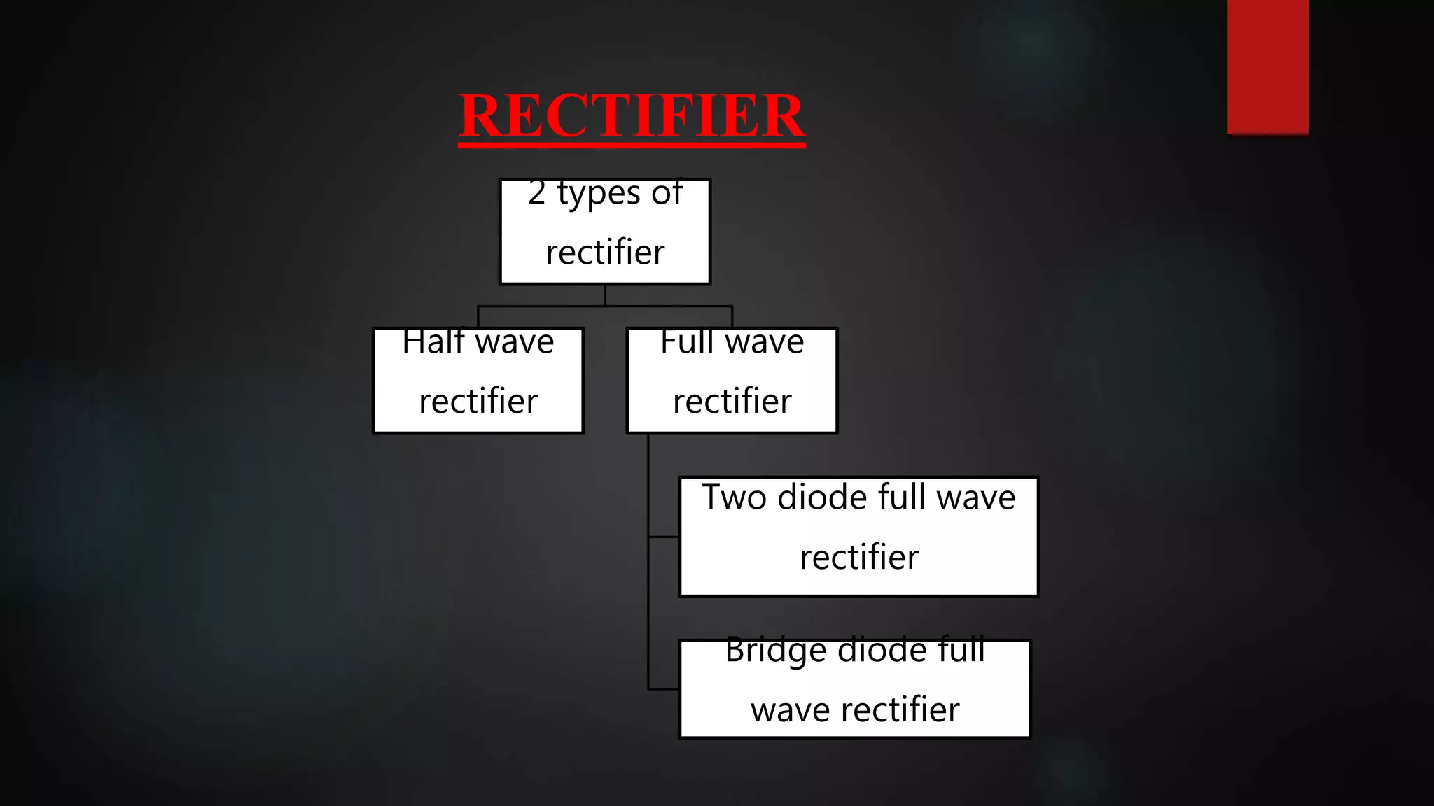
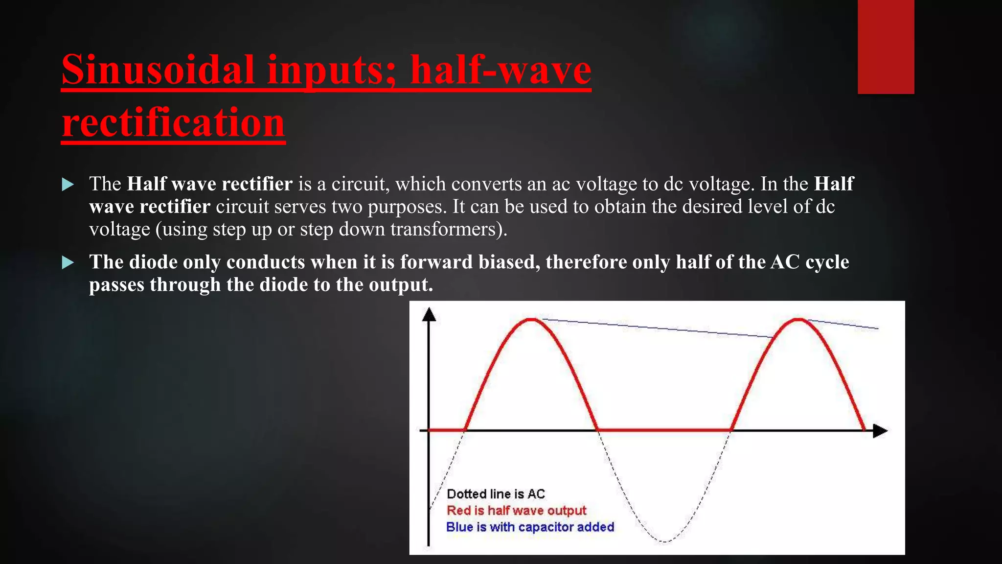
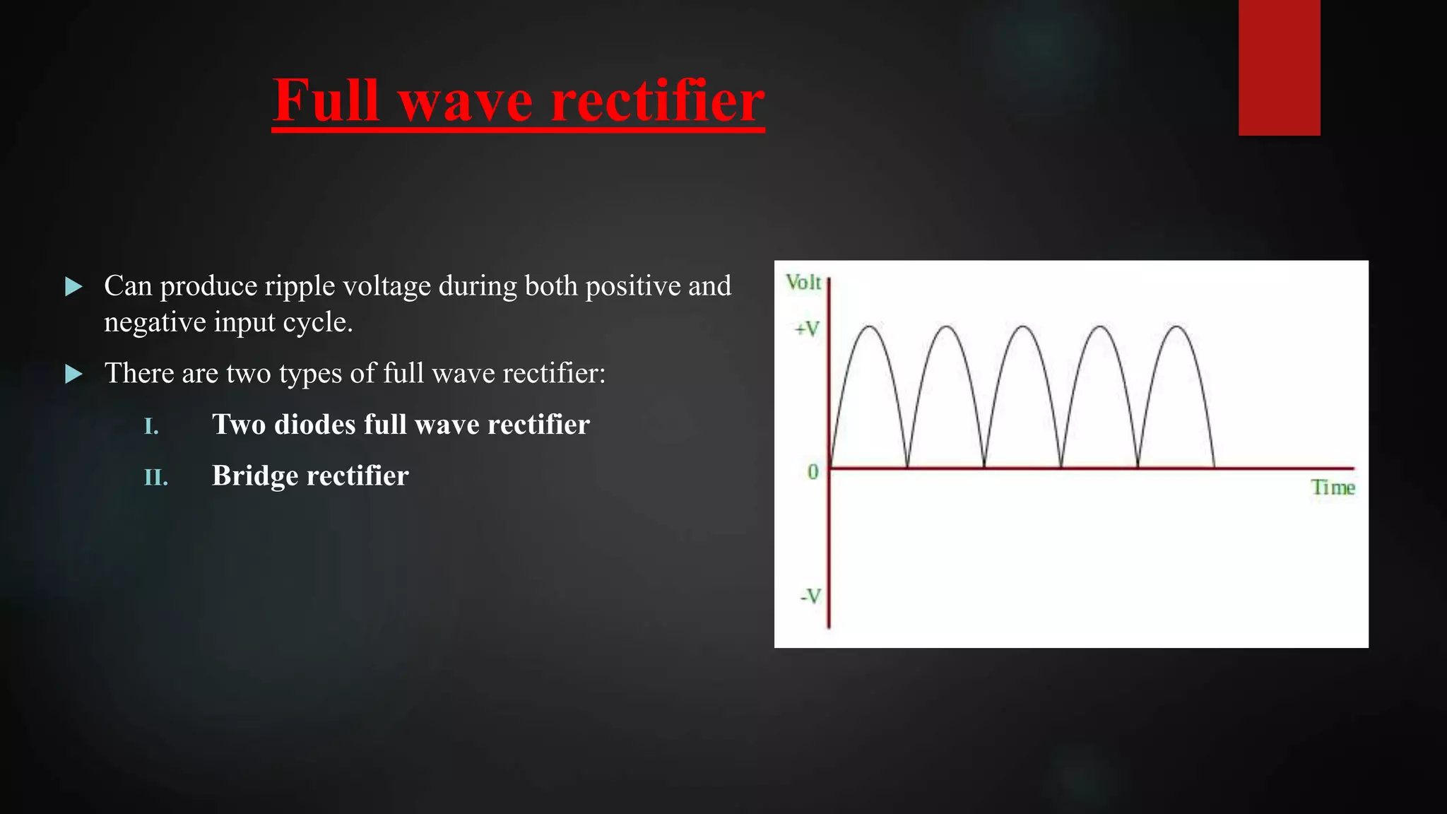
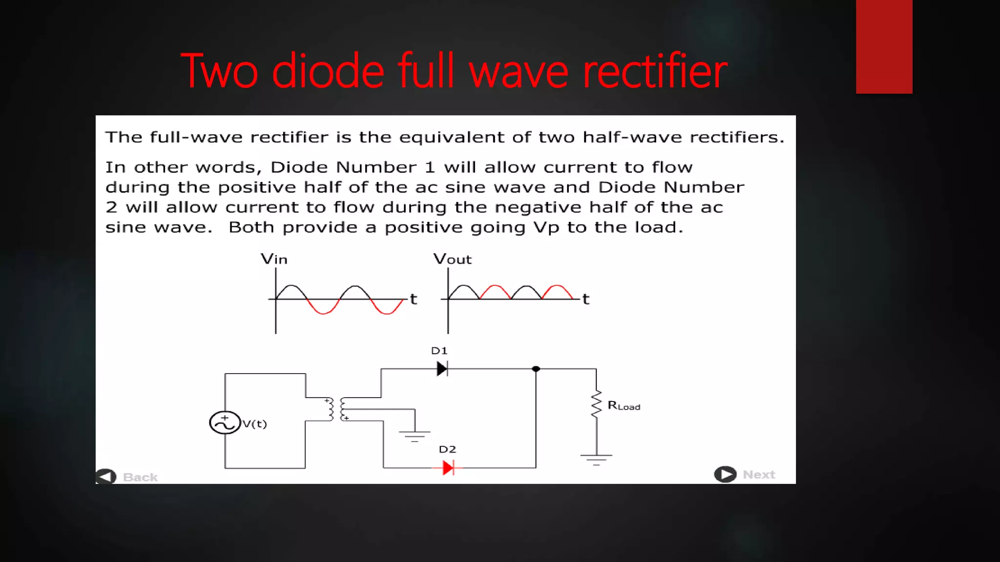
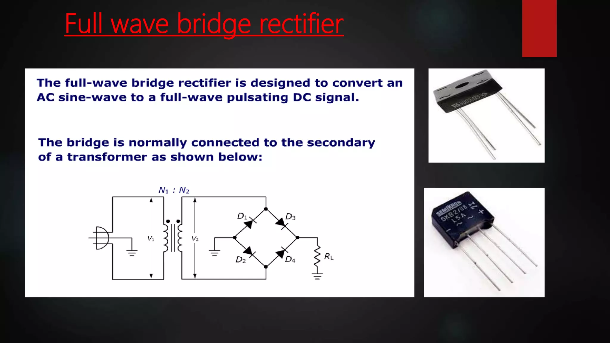
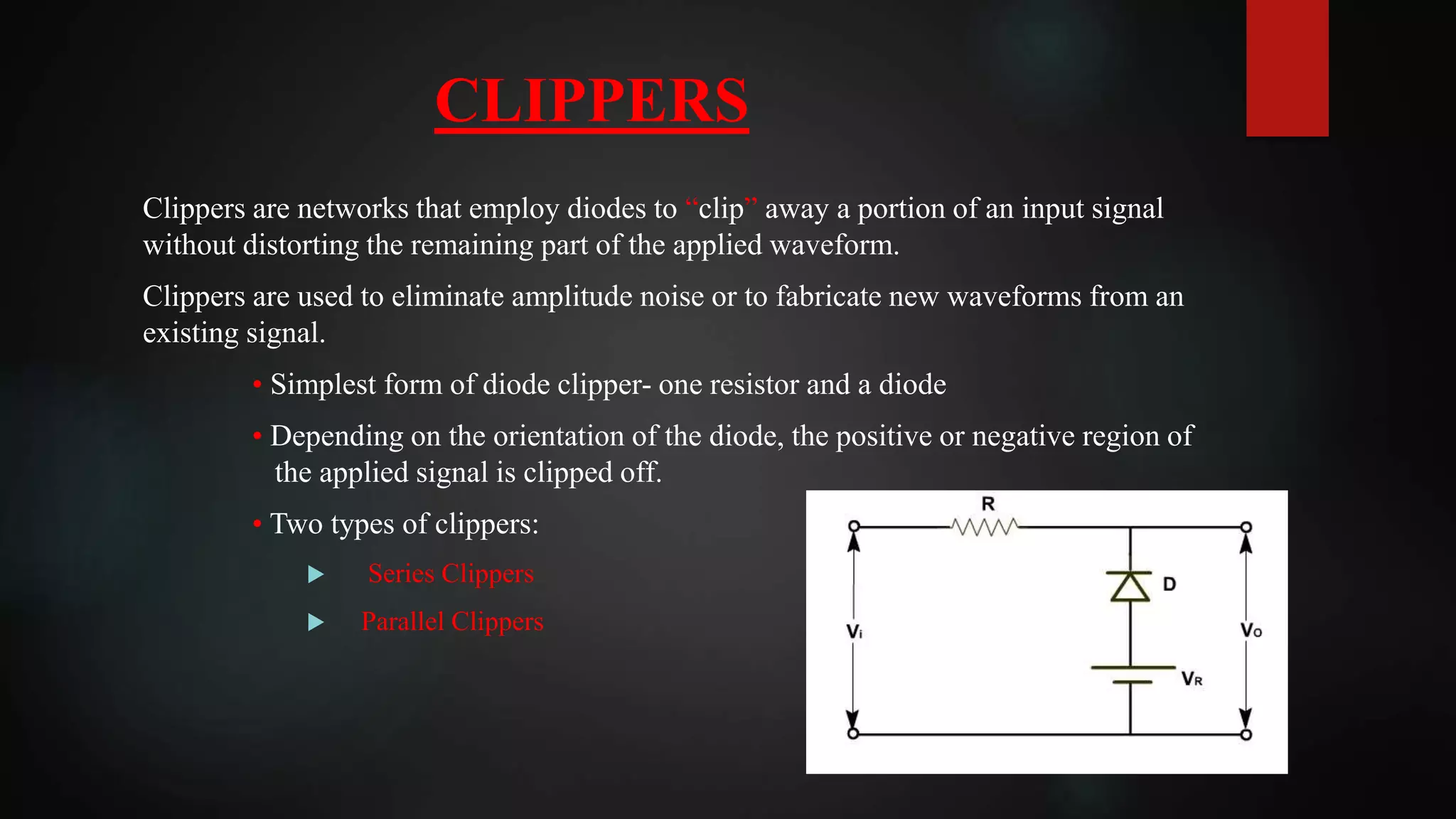
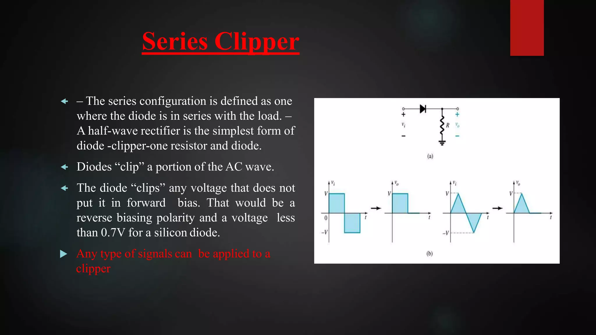
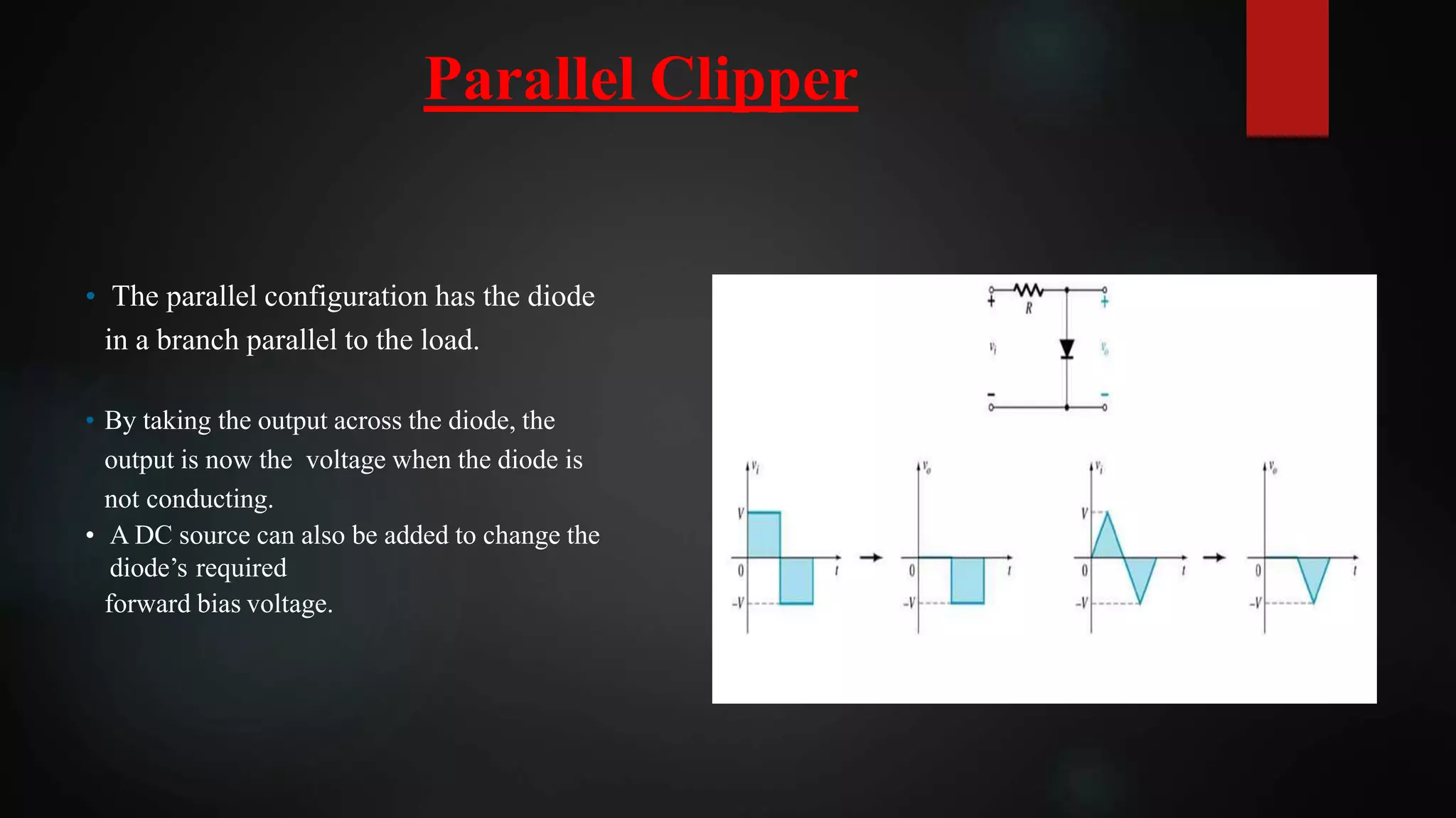
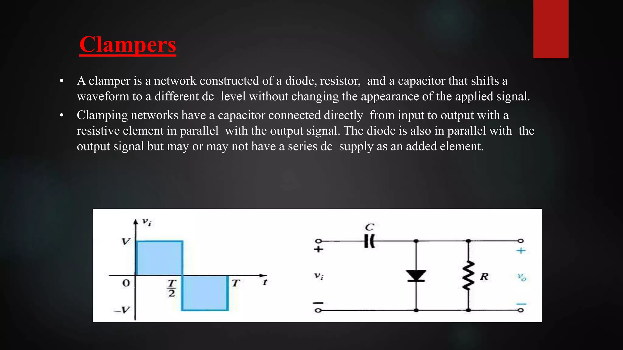
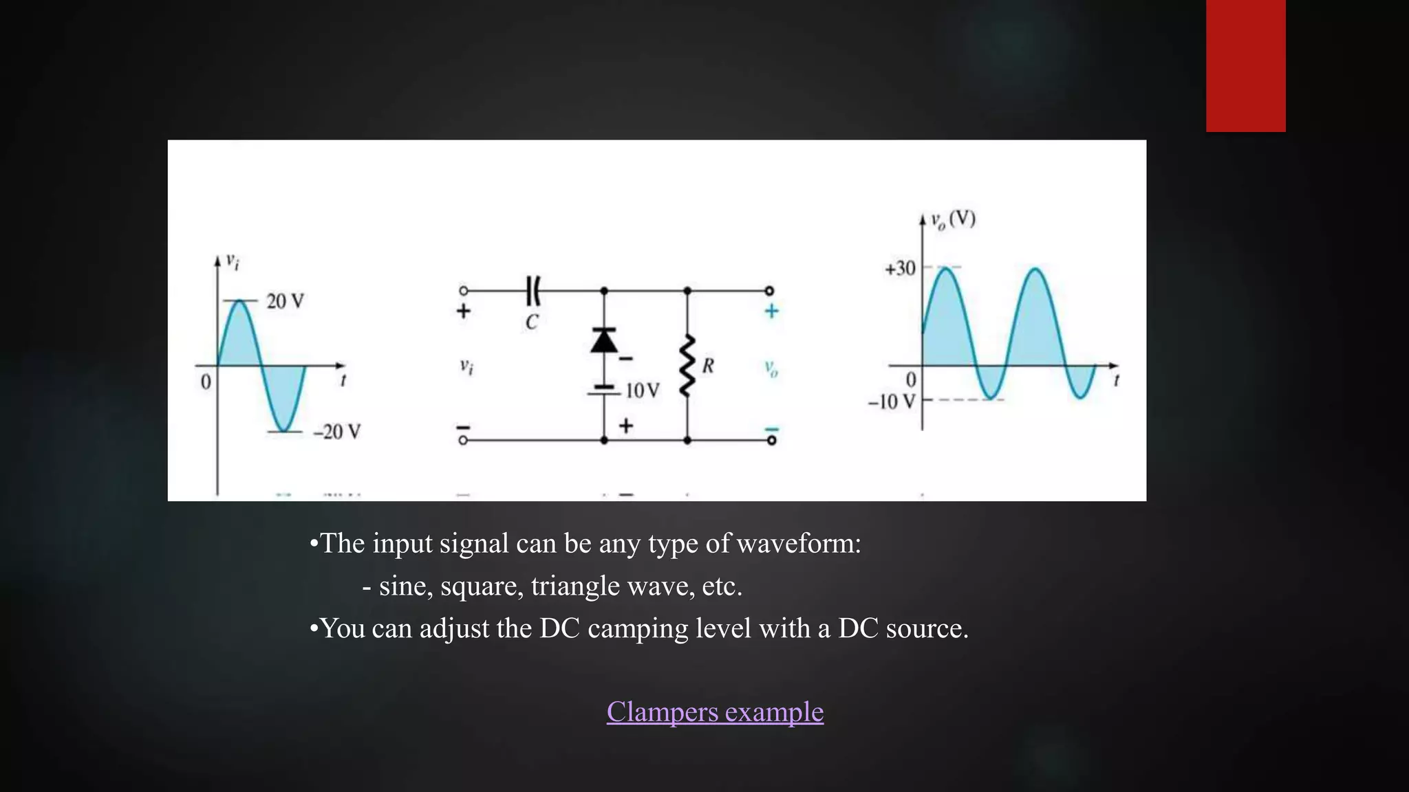
Diode Applications
Presented by:
• DANYAL FA16-BSE-187
• UMAR FAROOQ FA16-BSE-224
• MOHSIN IQBAL FA16-BSE-216
• SHAMEEM AKHTAR FA16-BSE-221
Chapter 2
Presented to:
Dr . Jawad
Introduction
A semiconductor device with two terminals,
typically allowing the flow of current in one
direction only.
A diode is a specialized electronic component with
two electrodes called the anode and the cathode.
Most diodes are made with semiconductor materials
such as silicon, germanium, or selenium.
Diode:
Load-Line Analysis
A load line is used in graphical analysis of
non-linear electronic circuits, representing the
constraint other parts of the circuit place on a
non-linear device, like a diode or transistor. It
is usually drawn on a graph of the current vs
voltage in the non-linear device, called the
device's characteristic curve.
Here, the equations are
ID=(E−VD)/R
ID=IX(exp(𝑉𝐷/𝑉𝑇)
−1)
Series Diode Configurations
Series connection means a side by side connection. When two
components are connected in series, they have one common
junction. The variation of voltage and current in a series connection
is as follows:
 Potential difference across every component is different.
 The current across every component connected in series remains
the same.
 The same properties also hold true for diodes when they are
connected in a series configuration.
Parallel Diode Configuration:
Parallel connection means the components are connected across each
other, having two common points. Current differs across each
component while voltage drop is same. When diodes are connected
in parallel, this same trend is observed.
• Current carrying capacity increases.
• No conduction in resultant diode in both
sides.
Series-parallel Configuration Diode
AND/OR Gates Diode:
Diode Logic OR gate (wired OR connection)
If one or both inputs are at logic “1” (5 volts), the current will flow through
one or both diodes. This current passes through the resistor and causes the
appearance of a voltage across its terminals, there by obtaining logic “1” on
the output.
We only get logic “0” (0 volts) on the output when both inputs are
in logic “0”. In this case, the diodes do not conduct, there is no current
through the resistor R and there is no voltage across its terminals. As a result
the voltage at Voult is the same as ground (0 volts)
 When both inputs are at logic “1″, the two diodes are
reverse biased and there is no current flowing
to ground. Therefore the output is logic “1” because
there is no voltage drop across the resistor R.
 If one of the inputs is logic “0”, the current will flow
through the corresponding diode and through the
resistor. Thus the diode anode (the output) will
be logic “0”.
 This method works fine when the circuits are simple,
but there are problems when you have to make
interconnections with such gates.
Diode Logic AND gate (wired AND connection)
RECTIFIER
2 types of
rectifier
Half wave
rectifier
Full wave
rectifier
Two diode full wave
rectifier
Bridge diode full
wave rectifier
Sinusoidal inputs; half-wave
rectification
 The Half wave rectifier is a circuit, which converts an ac voltage to dc voltage. In the Half
wave rectifier circuit serves two purposes. It can be used to obtain the desired level of dc
voltage (using step up or step down transformers).
 The diode only conducts when it is forward biased, therefore only half of the AC cycle
passes through the diode to the output.
Full wave rectifier
 Can produce ripple voltage during both positive and
negative input cycle.
 There are two types of full wave rectifier:
I. Two diodes full wave rectifier
II. Bridge rectifier
Two diode full wave rectifier
Full wave bridge rectifier
CLIPPERS
Clippers are networks that employ diodes to “clip” away a portion of an input signal
without distorting the remaining part of the applied waveform.
Clippers are used to eliminate amplitude noise or to fabricate new waveforms from an
existing signal.
• Simplest form of diode clipper- one resistor and a diode
• Depending on the orientation of the diode, the positive or negative region of
the applied signal is clipped off.
• Two types of clippers:
 Series Clippers
 Parallel Clippers
Series Clipper
 – The series configuration is defined as one
where the diode is in series with the load. –
A half-wave rectifier is the simplest form of
diode -clipper-one resistor and diode.
 Diodes “clip” a portion of the AC wave.
 The diode “clips” any voltage that does not
put it in forward bias. That would be a
reverse biasing polarity and a voltage less
than 0.7V for a silicon diode.
 Any type of signals can be applied to a
clipper
• The parallel configuration has the diode
in a branch parallel to the load.
• By taking the output across the diode, the
output is now the voltage when the diode is
not conducting.
• A DC source can also be added to change the
diode’s required
forward bias voltage.
Parallel Clipper
Clampers
• A clamper is a network constructed of a diode, resistor, and a capacitor that shifts a
waveform to a different dc level without changing the appearance of the applied signal.
• Clamping networks have a capacitor connected directly from input to output with a
resistive element in parallel with the output signal. The diode is also in parallel with the
output signal but may or may not have a series dc supply as an added element.
•The input signal can be any type of waveform:
- sine, square, triangle wave, etc.
•You can adjust the DC camping level with a DC source.
Clampers example
Chapter2

Chapter2

  • 1.
    Diode Applications Presented by: •DANYAL FA16-BSE-187 • UMAR FAROOQ FA16-BSE-224 • MOHSIN IQBAL FA16-BSE-216 • SHAMEEM AKHTAR FA16-BSE-221 Chapter 2 Presented to: Dr . Jawad
  • 2.
    Introduction A semiconductor devicewith two terminals, typically allowing the flow of current in one direction only. A diode is a specialized electronic component with two electrodes called the anode and the cathode. Most diodes are made with semiconductor materials such as silicon, germanium, or selenium. Diode:
  • 3.
    Load-Line Analysis A loadline is used in graphical analysis of non-linear electronic circuits, representing the constraint other parts of the circuit place on a non-linear device, like a diode or transistor. It is usually drawn on a graph of the current vs voltage in the non-linear device, called the device's characteristic curve. Here, the equations are ID=(E−VD)/R ID=IX(exp(𝑉𝐷/𝑉𝑇) −1)
  • 4.
    Series Diode Configurations Seriesconnection means a side by side connection. When two components are connected in series, they have one common junction. The variation of voltage and current in a series connection is as follows:  Potential difference across every component is different.  The current across every component connected in series remains the same.  The same properties also hold true for diodes when they are connected in a series configuration.
  • 5.
    Parallel Diode Configuration: Parallelconnection means the components are connected across each other, having two common points. Current differs across each component while voltage drop is same. When diodes are connected in parallel, this same trend is observed. • Current carrying capacity increases. • No conduction in resultant diode in both sides.
  • 6.
  • 7.
    AND/OR Gates Diode: DiodeLogic OR gate (wired OR connection) If one or both inputs are at logic “1” (5 volts), the current will flow through one or both diodes. This current passes through the resistor and causes the appearance of a voltage across its terminals, there by obtaining logic “1” on the output. We only get logic “0” (0 volts) on the output when both inputs are in logic “0”. In this case, the diodes do not conduct, there is no current through the resistor R and there is no voltage across its terminals. As a result the voltage at Voult is the same as ground (0 volts)
  • 8.
     When bothinputs are at logic “1″, the two diodes are reverse biased and there is no current flowing to ground. Therefore the output is logic “1” because there is no voltage drop across the resistor R.  If one of the inputs is logic “0”, the current will flow through the corresponding diode and through the resistor. Thus the diode anode (the output) will be logic “0”.  This method works fine when the circuits are simple, but there are problems when you have to make interconnections with such gates. Diode Logic AND gate (wired AND connection)
  • 9.
    RECTIFIER 2 types of rectifier Halfwave rectifier Full wave rectifier Two diode full wave rectifier Bridge diode full wave rectifier
  • 10.
    Sinusoidal inputs; half-wave rectification The Half wave rectifier is a circuit, which converts an ac voltage to dc voltage. In the Half wave rectifier circuit serves two purposes. It can be used to obtain the desired level of dc voltage (using step up or step down transformers).  The diode only conducts when it is forward biased, therefore only half of the AC cycle passes through the diode to the output.
  • 11.
    Full wave rectifier Can produce ripple voltage during both positive and negative input cycle.  There are two types of full wave rectifier: I. Two diodes full wave rectifier II. Bridge rectifier
  • 12.
    Two diode fullwave rectifier
  • 13.
  • 14.
    CLIPPERS Clippers are networksthat employ diodes to “clip” away a portion of an input signal without distorting the remaining part of the applied waveform. Clippers are used to eliminate amplitude noise or to fabricate new waveforms from an existing signal. • Simplest form of diode clipper- one resistor and a diode • Depending on the orientation of the diode, the positive or negative region of the applied signal is clipped off. • Two types of clippers:  Series Clippers  Parallel Clippers
  • 15.
    Series Clipper  –The series configuration is defined as one where the diode is in series with the load. – A half-wave rectifier is the simplest form of diode -clipper-one resistor and diode.  Diodes “clip” a portion of the AC wave.  The diode “clips” any voltage that does not put it in forward bias. That would be a reverse biasing polarity and a voltage less than 0.7V for a silicon diode.  Any type of signals can be applied to a clipper
  • 16.
    • The parallelconfiguration has the diode in a branch parallel to the load. • By taking the output across the diode, the output is now the voltage when the diode is not conducting. • A DC source can also be added to change the diode’s required forward bias voltage. Parallel Clipper
  • 17.
    Clampers • A clamperis a network constructed of a diode, resistor, and a capacitor that shifts a waveform to a different dc level without changing the appearance of the applied signal. • Clamping networks have a capacitor connected directly from input to output with a resistive element in parallel with the output signal. The diode is also in parallel with the output signal but may or may not have a series dc supply as an added element.
  • 18.
    •The input signalcan be any type of waveform: - sine, square, triangle wave, etc. •You can adjust the DC camping level with a DC source. Clampers example