Downloaded 83 times


![Memory-less systems [outputs don’t depend on past values of
input(s), opposite to Dynamic systems.]
Memory-less linear systems
y(t) = x(t)
Memory-less nonlinear systems
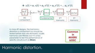
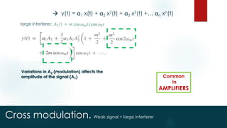
y(t) = 1 x(t) + 2 x2(t) + 3 x3(t) +… n xn(t)
If j=0 for even j, the system is said to
have odd symmetry, when his
response to –x(t) is negative to that to
x(t).
The circuit having this property is
called differential or balanced.](https://image.slidesharecdn.com/lecture-1-150317154931-conversion-gate01/85/RF-Microelectronics-Basic-concepts-nonlinearity-13-320.jpg)
![Nonlinearity effects.
y(t) = 1 x(t) + 2 x2(t) + 3 x3(t) +… n xn(t)
DC
component
Total
Gain
[compression
@ 1 3 <0]
2nd
harmonic
Suppresse
d for odd
symmetry.
3rd
harmonic
Small
signal
gain](https://image.slidesharecdn.com/lecture-1-150317154931-conversion-gate01/85/RF-Microelectronics-Basic-concepts-nonlinearity-14-320.jpg)
![Gain compression
y(t) = 1 x(t) + 2 x2(t) + 3 x3(t) +… n xn(t)
DC
component
Total
Gain
[compression
@ 1 3 <0]
2nd
harmonic
Suppresse
d for odd
symmetry.
3rd
harmonic
Small
signal
gain
@ 1 3 <0 the gain is compressed as A rises
1 =500
3 =-0.1](https://image.slidesharecdn.com/lecture-1-150317154931-conversion-gate01/85/RF-Microelectronics-Basic-concepts-nonlinearity-16-320.jpg)
![Gain compression [1-dB compression point]
@ 1-dB compression point, the gain is
reduced by 10%
Desensitization: when large
interferer [blocker] causes gain
compression while sensing weak
desired signal.
[lowers the SNR]](https://image.slidesharecdn.com/lecture-1-150317154931-conversion-gate01/85/RF-Microelectronics-Basic-concepts-nonlinearity-17-320.jpg)


![Intermodulation[two-tone test].
Two signals with
small A
is chosen to minimize
nonlinearity effect on it
Gain = 1
Fundamental A
IM products A3
Plot in log-log scale,
the intersection is
the third-order
intercept point
IIP3 is beyond the allowable
input range or even higher
than the supply voltage,
because if the input level
reached the AIP3 the gain
drops and higher order IM
products become significant.](https://image.slidesharecdn.com/lecture-1-150317154931-conversion-gate01/85/RF-Microelectronics-Basic-concepts-nonlinearity-21-320.jpg)
![Intermodulation[two-tone test].
IIP3 is chosen beyond the allowable
input range or even higher than the
supply voltage, because if the input
level reached the AIP3 the gain drops
and higher order IM products
become significant.
AIIP3 is greater than
the 1-dB compression
point with 9.6 dB](https://image.slidesharecdn.com/lecture-1-150317154931-conversion-gate01/85/RF-Microelectronics-Basic-concepts-nonlinearity-22-320.jpg)
![IIP3 direct calculation. [two-tone test].](https://image.slidesharecdn.com/lecture-1-150317154931-conversion-gate01/85/RF-Microelectronics-Basic-concepts-nonlinearity-23-320.jpg)


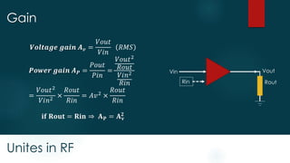
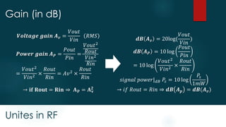
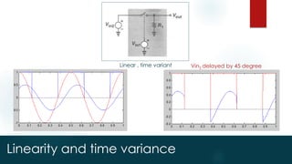
This document provides an introduction to basic RF concepts including nonlinearity, noise, impedance transformation, gain, linearity and time variance, harmonic distortion, gain compression, cross modulation, and intermodulation. It discusses key effects like how nonlinearity can lead to harmonic distortion and intermodulation distortion, and how gain compression occurs when the input power is increased. It also introduces important RF parameters for characterizing devices and circuits like the 1 dB compression point and third order intercept point.
![RF Module Design - [Chapter 4] Transceiver Architecture](https://cdn.slidesharecdn.com/ss_thumbnails/rfch4-150613070346-lva1-app6891-thumbnail.jpg?width=640&height=640&fit=bounds)

![RF Circuit Design - [Ch4-2] LNA, PA, and Broadband Amplifier](https://cdn.slidesharecdn.com/ss_thumbnails/ch4-2-150613064410-lva1-app6891-thumbnail.jpg?width=640&height=640&fit=bounds)
![RF Circuit Design - [Ch4-1] Microwave Transistor Amplifier](https://cdn.slidesharecdn.com/ss_thumbnails/ch4-1-150613064409-lva1-app6892-thumbnail.jpg?width=640&height=640&fit=bounds)

![Multiband Transceivers - [Chapter 7] Multi-mode/Multi-band GSM/GPRS/TDMA/AMP...](https://cdn.slidesharecdn.com/ss_thumbnails/ch7-150613070936-lva1-app6892-thumbnail.jpg?width=640&height=640&fit=bounds)
![Multiband Transceivers - [Chapter 6] Multi-mode and Multi-band Transceivers](https://cdn.slidesharecdn.com/ss_thumbnails/ch6-150613070935-lva1-app6891-thumbnail.jpg?width=640&height=640&fit=bounds)

![RF Module Design - [Chapter 6] Power Amplifier](https://cdn.slidesharecdn.com/ss_thumbnails/rfch6-150613070347-lva1-app6891-thumbnail.jpg?width=640&height=640&fit=bounds)
![RF Circuit Design - [Ch2-1] Resonator and Impedance Matching](https://cdn.slidesharecdn.com/ss_thumbnails/ch2-1-150613064353-lva1-app6892-thumbnail.jpg?width=640&height=640&fit=bounds)
![RF Module Design - [Chapter 7] Voltage-Controlled Oscillator](https://cdn.slidesharecdn.com/ss_thumbnails/rfch7-150613070347-lva1-app6892-thumbnail.jpg?width=640&height=640&fit=bounds)


![RF Module Design - [Chapter 5] Low Noise Amplifier](https://cdn.slidesharecdn.com/ss_thumbnails/rfch5-150613070346-lva1-app6891-thumbnail.jpg?width=640&height=640&fit=bounds)


![RF Module Design - [Chapter 2] Noises](https://cdn.slidesharecdn.com/ss_thumbnails/rfch2-150613070344-lva1-app6892-thumbnail.jpg?width=640&height=640&fit=bounds)


![RF Circuit Design - [Ch3-2] Power Waves and Power-Gain Expressions](https://cdn.slidesharecdn.com/ss_thumbnails/ch3-2-150613064404-lva1-app6891-thumbnail.jpg?width=640&height=640&fit=bounds)


![RF Module Design - [Chapter 3] Linearity](https://cdn.slidesharecdn.com/ss_thumbnails/rfch3-150613070345-lva1-app6891-thumbnail.jpg?width=640&height=640&fit=bounds)