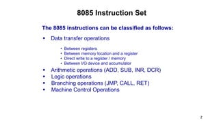
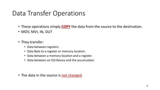
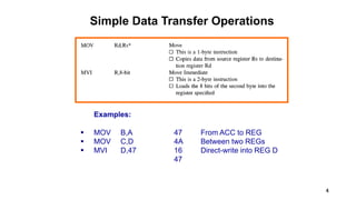
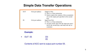
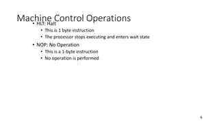
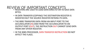
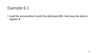
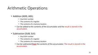
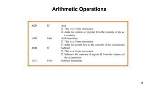
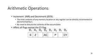
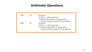
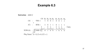
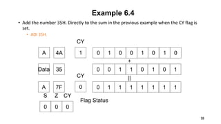
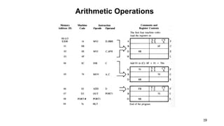
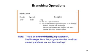
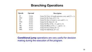
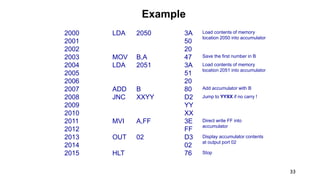
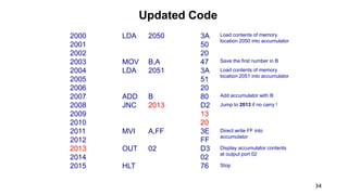
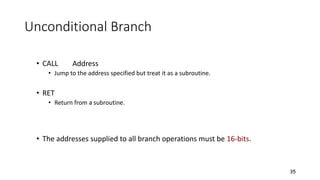
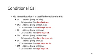
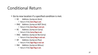
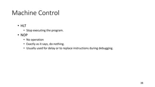
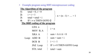
Chapter 6
Introduction to 8085
Instructions
1
2
8085 Instruction Set
The 8085 instructions can be classified as follows:
 Data transfer operations
 Arithmetic operations (ADD, SUB, INR, DCR)
 Logic operations
 Branching operations (JMP, CALL, RET)
 Machine Control Operations
• Between registers
• Between memory location and a register
• Direct write to a register / memory
• Between I/O device and accumulator
Data Transfer Operations
• These operations simply COPY the data from the source to the destination.
• MOV, MVI, IN, OUT
• They transfer:
• Data between registers.
• Data Byte to a register or memory location.
• Data between a memory location and a register.
• Data between an IO Device and the accumulator.
• The data in the source is not changed.
3
4
Simple Data Transfer Operations
Examples:
 MOV B,A 47 From ACC to REG
 MOV C,D 4A Between two REGs
 MVI D,47 16 Direct-write into REG D
47
5
Simple Data Transfer Operations
Example:
 OUT 05 D3
05
Contents of ACC sent to output port number 05.
Machine Control Operations• HLT: Halt
• This is 1 byte instruction
• The processor stops executing and enters wait state
• NOP: No Operation
• This is a 1-byte instruction
• No operation is performed
6
REVIEW OF IMPORTANT CONCEPTS• REGISTERS ARE USED TO LOAD DATA DIRECTLY OR TO SAVE DATA
BYTES.
• IN DATA TRANSFER (COPYING) THE DESTINATION REGISTER IS
MODIFIED BUT THE SOURCE REGISTER RETAINS ITS DATA.
• THE 8085 TRANSFERS DATA FROM AN INPUT PORT TO THE
ACCUMULATOR (IN) AND FROM THE ACCUMULATOR TO AN
OUTPUT PORT (OUT). THE INSTRUCTION OUT CANNOT SEND DATA
FROM ANY OTHER REGISTER.
• IN THE 8085 PROCESSOR, DATA TRANSFER INSTRUCTION DO NOT
AFFECT THE FLAGS.
7
Example 6.1
• Load the accumulator A with the data byte 82h. And save the data in
register B.
8
Example 6.1
• Load the accumulator A with the data byte 82h. And save the data in
register B.
• MVI A, 82H.
• MOV B, A
• The first instruction is a 2-byte instruction that loads the accumulator
with the data byte 82h., and the second instruction copies the
contents of the accumulator in register B without changing the
contents of the accumulator.
9
Reading Data at Input Port and Sending Data to Output Port
10
11
Example 6.2
• Write instructions to read eight ON/OFF switches connected to the
input with the address 00H. And turn on the devices connected to the
output port with the address 01H. As shown in figure.
• IN 00H.
• OUT 01H.
• HLT
12
Arithmetic Operations
• Addition (ADD, ADI):
• Any 8-bit number.
• The contents of a register.
• The contents of a memory location.
• Can be added to the contents of the accumulator and the result is stored in the
accumulator.
• Subtraction (SUB, SUI):
• Any 8-bit number
• The contents of a register
• The contents of a memory location
• Can be subtracted from the contents of the accumulator. The result is stored in the
accumulator.
13
14
Arithmetic Operations
• Increment (INR) and Decrement (DCR):
• The 8-bit contents of any memory location or any register can be directly incremented or
decremented by 1.
• No need to disturb the contents of the accumulator.
• Affect all flags except the CY flag.
15
S Z AC P CY
D7 D6 D5 D4 D3 D2 D1 D0
16
Arithmetic Operations
17
Example 6.3
• Add the number 35H. Directly to the sum in the previous example when the CY flag is
set.
• ADI 35H.
18
Example 6.4
0 0 0
S Z CY
Flag Status
0 0 1 1 0 1 0 1
0 1 0 0 1 0 1 0
35
4A
0 1 1 1 1 1 1 17F
Data
A
A
+
||
1
CY
0
CY
19
Arithmetic Operations
REVIEW OF IMPORTANT CONCEPTS• The arithmetic operations implicitly assume that the contents of the accumulator are one of the
operands.
• The result of the arithmetic operations are stored in the accumulator; thus, the previous contents
of the content of the accumulator are altered.
• The flags are modified to reflect the data conditions of an operation.
• In the Add operation, if the sum is larger than 8-bit CY is set.
• The Substract operation is performed by using the 2’s complement method.
• If a substraction results in a negative number, the answersis in 2’s complement and CY (the Borrow
flag)
• In unsigned arithmetic operations, the Sign flag (S) should be ignored.
• The instructions INR and DCR are special cases of the arithmetic operations. These instructions can
be used for any of the registers, and they do not affect CY, even if the result is larger than 8-bit. All
other flags are affected by the result in the register used (not by the contents of the accumulator).
20
Logic Operations
• These instructions perform logic operations on the contents of the accumulator.
• ANA, ANI, ORA, ORI, XRA and XRI
• Source: Accumulator and
• An 8-bit number
• The contents of a register
• The contents of a memory location
• Destination: Accumulator
ANA R/M AND Accumulator With Reg/Mem
ANI # AND Accumulator With an 8-bit number
ORA R/M OR Accumulator With Reg/Mem
ORI # OR Accumulator With an 8-bit number
XRA R/M XOR Accumulator With Reg/Mem
XRI # XOR Accumulator With an 8-bit number
21
22
Logic Operations
23
Logic Operations
24
Logic Operations
25
Overview of Logic Operations
Data Masking With Logic AND
26
Branch Operations
• Three Types
• Jump instructions
• Call and Return Instructions
• Restart Instructions
27
JUMP Instructions
• Two types:
• Unconditional jump.
• Go to a new location no matter what.
• JMP Address
• Jump to the address specified (Go to).
• Conditional jump.
• Go to a new location if the condition is true.
• The addresses supplied to all branch operations must be 16-bits.
28
29
Branching Operations
Note: This is an unconditional jump operation.
It will always force the program counter to a fixed
memory address continuous loop !
30
Branching Operations
Conditional jump operations are very useful for decision
making during the execution of the program.
Conditional Jump
• Go to new location if a specified condition is met.
• JZ Address (Jump on Zero)
• Go to address specified if the Zero flag is set.
• JNZ Address (Jump on NOT Zero)
• Go to address specified if the Zero flag is not set.
• JC Address (Jump on Carry)
• Go to the address specified if the Carry flag is set.
• JNC Address (Jump on No Carry)
• Go to the address specified if the Carry flag is not set.
• JP Address (Jump on Plus)
• Go to the address specified if the Sign flag is not set
• JM Address (Jump on Minus)
• Go to the address specified if the Sign flag is set.
31
32
Example
Write a 8085 machine code program:
 Read two different memory locations (2050H.
& 2051H.)
 Add the contents
 Send the result to output port 02 (display)
if there is no overflow
 Display “FF” if there is an overflow
 Stop
Assume that the 8085 program begin at
2000H.
33
Example
2000 LDA 2050 3A
2001 50
2002 20
2003 MOV B,A 47
2004 LDA 2051 3A
2005 51
2006 20
2007 ADD B 80
2008 JNC XXYY D2
2009 YY
2010 XX
2011 MVI A,FF 3E
2012 FF
2013 OUT 02 D3
2014 02
2015 HLT 76
Load contents of memory
location 2050 into accumulator
Load contents of memory
location 2051 into accumulator
Save the first number in B
Add accumulator with B
Jump to YYXX if no carry !
Direct write FF into
accumulator
Display accumulator contents
at output port 02
Stop
34
Updated Code
2000 LDA 2050 3A
2001 50
2002 20
2003 MOV B,A 47
2004 LDA 2051 3A
2005 51
2006 20
2007 ADD B 80
2008 JNC 2013 D2
2009 13
2010 20
2011 MVI A,FF 3E
2012 FF
2013 OUT 02 D3
2014 02
2015 HLT 76
Load contents of memory
location 2050 into accumulator
Load contents of memory
location 2051 into accumulator
Save the first number in B
Add accumulator with B
Jump to 2013 if no carry !
Direct write FF into
accumulator
Display accumulator contents
at output port 02
Stop
Unconditional Branch
• CALL Address
• Jump to the address specified but treat it as a subroutine.
• RET
• Return from a subroutine.
• The addresses supplied to all branch operations must be 16-bits.
35
Conditional Call
• Go to new location if a specified condition is met.
• CZ Address (Jump on Zero)
• Call subroutine if the Zero flag is set.
• CNZ Address (Jump on NOT Zero)
• Call subroutine if the Zero flag is not set.
• CC Address (Jump on Carry)
• Call subroutine if the Carry flag is set.
• CNC Address (Jump on No Carry)
• Call subroutine if the Carry flag is not set.
• CP Address (Jump on Plus)
• Call subroutine if the Sign flag is not set
• CM Address (Jump on Minus)
• Call subroutine if the Sign flag is set.
36
Conditional Return
• Go to new location if a specified condition is met.
• RZ Address (Jump on Zero)
• Return if the Zero flag is set.
• RNZ Address (Jump on NOT Zero)
• Return if the Zero flag is not set.
• RC Address (Jump on Carry)
• Return if the Carry flag is set.
• RNC Address (Jump on No Carry)
• Return if the Carry flag is not set.
• RP Address (Jump on Plus)
• Return if the Sign flag is not set
• RM Address (Jump on Minus)
• Return if the Sign flag is set.
37
Machine Control
• HLT
• Stop executing the program.
• NOP
• No operation
• Exactly as it says, do nothing.
• Usually used for delay or to replace instructions during debugging.
38
39
The Algorithm of the program
1: total = 0, i = 0
2: i = i + 1
3: total = total + i
4: IF i  n THEN GOTO 2
n + (n - 1) + … + 1
The 8085 coding of the program
LDA n
MOV B, A
XRA A
Loop: ADD B
DCR B
JNZ Loop
STA total
• Example program using 8085 microprocessor coding
i = n
sum = A  A = 0
sum = sum + i
i = i - 1
IF i  0 THEN GOTO Loop
total = sum

Chapter 6 - Introduction to 8085 Instructions

  • 1.
    Chapter 6 Introduction to8085 Instructions 1
  • 2.
    2 8085 Instruction Set The8085 instructions can be classified as follows:  Data transfer operations  Arithmetic operations (ADD, SUB, INR, DCR)  Logic operations  Branching operations (JMP, CALL, RET)  Machine Control Operations • Between registers • Between memory location and a register • Direct write to a register / memory • Between I/O device and accumulator
  • 3.
    Data Transfer Operations •These operations simply COPY the data from the source to the destination. • MOV, MVI, IN, OUT • They transfer: • Data between registers. • Data Byte to a register or memory location. • Data between a memory location and a register. • Data between an IO Device and the accumulator. • The data in the source is not changed. 3
  • 4.
    4 Simple Data TransferOperations Examples:  MOV B,A 47 From ACC to REG  MOV C,D 4A Between two REGs  MVI D,47 16 Direct-write into REG D 47
  • 5.
    5 Simple Data TransferOperations Example:  OUT 05 D3 05 Contents of ACC sent to output port number 05.
  • 6.
    Machine Control Operations•HLT: Halt • This is 1 byte instruction • The processor stops executing and enters wait state • NOP: No Operation • This is a 1-byte instruction • No operation is performed 6
  • 7.
    REVIEW OF IMPORTANTCONCEPTS• REGISTERS ARE USED TO LOAD DATA DIRECTLY OR TO SAVE DATA BYTES. • IN DATA TRANSFER (COPYING) THE DESTINATION REGISTER IS MODIFIED BUT THE SOURCE REGISTER RETAINS ITS DATA. • THE 8085 TRANSFERS DATA FROM AN INPUT PORT TO THE ACCUMULATOR (IN) AND FROM THE ACCUMULATOR TO AN OUTPUT PORT (OUT). THE INSTRUCTION OUT CANNOT SEND DATA FROM ANY OTHER REGISTER. • IN THE 8085 PROCESSOR, DATA TRANSFER INSTRUCTION DO NOT AFFECT THE FLAGS. 7
  • 8.
    Example 6.1 • Loadthe accumulator A with the data byte 82h. And save the data in register B. 8
  • 9.
    Example 6.1 • Loadthe accumulator A with the data byte 82h. And save the data in register B. • MVI A, 82H. • MOV B, A • The first instruction is a 2-byte instruction that loads the accumulator with the data byte 82h., and the second instruction copies the contents of the accumulator in register B without changing the contents of the accumulator. 9
  • 10.
    Reading Data atInput Port and Sending Data to Output Port 10
  • 11.
  • 12.
    Example 6.2 • Writeinstructions to read eight ON/OFF switches connected to the input with the address 00H. And turn on the devices connected to the output port with the address 01H. As shown in figure. • IN 00H. • OUT 01H. • HLT 12
  • 13.
    Arithmetic Operations • Addition(ADD, ADI): • Any 8-bit number. • The contents of a register. • The contents of a memory location. • Can be added to the contents of the accumulator and the result is stored in the accumulator. • Subtraction (SUB, SUI): • Any 8-bit number • The contents of a register • The contents of a memory location • Can be subtracted from the contents of the accumulator. The result is stored in the accumulator. 13
  • 14.
  • 15.
    Arithmetic Operations • Increment(INR) and Decrement (DCR): • The 8-bit contents of any memory location or any register can be directly incremented or decremented by 1. • No need to disturb the contents of the accumulator. • Affect all flags except the CY flag. 15 S Z AC P CY D7 D6 D5 D4 D3 D2 D1 D0
  • 16.
  • 17.
  • 18.
    • Add thenumber 35H. Directly to the sum in the previous example when the CY flag is set. • ADI 35H. 18 Example 6.4 0 0 0 S Z CY Flag Status 0 0 1 1 0 1 0 1 0 1 0 0 1 0 1 0 35 4A 0 1 1 1 1 1 1 17F Data A A + || 1 CY 0 CY
  • 19.
  • 20.
    REVIEW OF IMPORTANTCONCEPTS• The arithmetic operations implicitly assume that the contents of the accumulator are one of the operands. • The result of the arithmetic operations are stored in the accumulator; thus, the previous contents of the content of the accumulator are altered. • The flags are modified to reflect the data conditions of an operation. • In the Add operation, if the sum is larger than 8-bit CY is set. • The Substract operation is performed by using the 2’s complement method. • If a substraction results in a negative number, the answersis in 2’s complement and CY (the Borrow flag) • In unsigned arithmetic operations, the Sign flag (S) should be ignored. • The instructions INR and DCR are special cases of the arithmetic operations. These instructions can be used for any of the registers, and they do not affect CY, even if the result is larger than 8-bit. All other flags are affected by the result in the register used (not by the contents of the accumulator). 20
  • 21.
    Logic Operations • Theseinstructions perform logic operations on the contents of the accumulator. • ANA, ANI, ORA, ORI, XRA and XRI • Source: Accumulator and • An 8-bit number • The contents of a register • The contents of a memory location • Destination: Accumulator ANA R/M AND Accumulator With Reg/Mem ANI # AND Accumulator With an 8-bit number ORA R/M OR Accumulator With Reg/Mem ORI # OR Accumulator With an 8-bit number XRA R/M XOR Accumulator With Reg/Mem XRI # XOR Accumulator With an 8-bit number 21
  • 22.
  • 23.
  • 24.
  • 25.
  • 26.
    Data Masking WithLogic AND 26
  • 27.
    Branch Operations • ThreeTypes • Jump instructions • Call and Return Instructions • Restart Instructions 27
  • 28.
    JUMP Instructions • Twotypes: • Unconditional jump. • Go to a new location no matter what. • JMP Address • Jump to the address specified (Go to). • Conditional jump. • Go to a new location if the condition is true. • The addresses supplied to all branch operations must be 16-bits. 28
  • 29.
    29 Branching Operations Note: Thisis an unconditional jump operation. It will always force the program counter to a fixed memory address continuous loop !
  • 30.
    30 Branching Operations Conditional jumpoperations are very useful for decision making during the execution of the program.
  • 31.
    Conditional Jump • Goto new location if a specified condition is met. • JZ Address (Jump on Zero) • Go to address specified if the Zero flag is set. • JNZ Address (Jump on NOT Zero) • Go to address specified if the Zero flag is not set. • JC Address (Jump on Carry) • Go to the address specified if the Carry flag is set. • JNC Address (Jump on No Carry) • Go to the address specified if the Carry flag is not set. • JP Address (Jump on Plus) • Go to the address specified if the Sign flag is not set • JM Address (Jump on Minus) • Go to the address specified if the Sign flag is set. 31
  • 32.
    32 Example Write a 8085machine code program:  Read two different memory locations (2050H. & 2051H.)  Add the contents  Send the result to output port 02 (display) if there is no overflow  Display “FF” if there is an overflow  Stop Assume that the 8085 program begin at 2000H.
  • 33.
    33 Example 2000 LDA 20503A 2001 50 2002 20 2003 MOV B,A 47 2004 LDA 2051 3A 2005 51 2006 20 2007 ADD B 80 2008 JNC XXYY D2 2009 YY 2010 XX 2011 MVI A,FF 3E 2012 FF 2013 OUT 02 D3 2014 02 2015 HLT 76 Load contents of memory location 2050 into accumulator Load contents of memory location 2051 into accumulator Save the first number in B Add accumulator with B Jump to YYXX if no carry ! Direct write FF into accumulator Display accumulator contents at output port 02 Stop
  • 34.
    34 Updated Code 2000 LDA2050 3A 2001 50 2002 20 2003 MOV B,A 47 2004 LDA 2051 3A 2005 51 2006 20 2007 ADD B 80 2008 JNC 2013 D2 2009 13 2010 20 2011 MVI A,FF 3E 2012 FF 2013 OUT 02 D3 2014 02 2015 HLT 76 Load contents of memory location 2050 into accumulator Load contents of memory location 2051 into accumulator Save the first number in B Add accumulator with B Jump to 2013 if no carry ! Direct write FF into accumulator Display accumulator contents at output port 02 Stop
  • 35.
    Unconditional Branch • CALLAddress • Jump to the address specified but treat it as a subroutine. • RET • Return from a subroutine. • The addresses supplied to all branch operations must be 16-bits. 35
  • 36.
    Conditional Call • Goto new location if a specified condition is met. • CZ Address (Jump on Zero) • Call subroutine if the Zero flag is set. • CNZ Address (Jump on NOT Zero) • Call subroutine if the Zero flag is not set. • CC Address (Jump on Carry) • Call subroutine if the Carry flag is set. • CNC Address (Jump on No Carry) • Call subroutine if the Carry flag is not set. • CP Address (Jump on Plus) • Call subroutine if the Sign flag is not set • CM Address (Jump on Minus) • Call subroutine if the Sign flag is set. 36
  • 37.
    Conditional Return • Goto new location if a specified condition is met. • RZ Address (Jump on Zero) • Return if the Zero flag is set. • RNZ Address (Jump on NOT Zero) • Return if the Zero flag is not set. • RC Address (Jump on Carry) • Return if the Carry flag is set. • RNC Address (Jump on No Carry) • Return if the Carry flag is not set. • RP Address (Jump on Plus) • Return if the Sign flag is not set • RM Address (Jump on Minus) • Return if the Sign flag is set. 37
  • 38.
    Machine Control • HLT •Stop executing the program. • NOP • No operation • Exactly as it says, do nothing. • Usually used for delay or to replace instructions during debugging. 38
  • 39.
    39 The Algorithm ofthe program 1: total = 0, i = 0 2: i = i + 1 3: total = total + i 4: IF i  n THEN GOTO 2 n + (n - 1) + … + 1 The 8085 coding of the program LDA n MOV B, A XRA A Loop: ADD B DCR B JNZ Loop STA total • Example program using 8085 microprocessor coding i = n sum = A  A = 0 sum = sum + i i = i - 1 IF i  0 THEN GOTO Loop total = sum