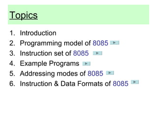
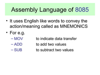
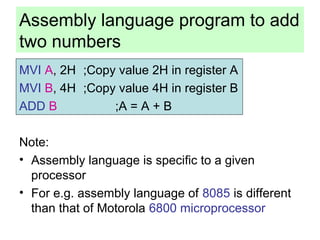
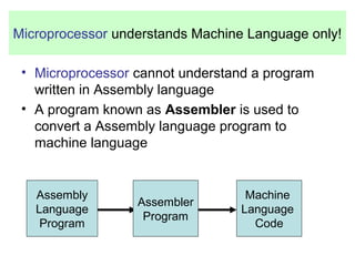
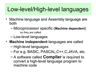
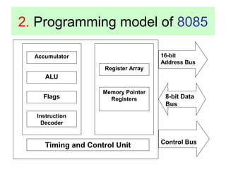
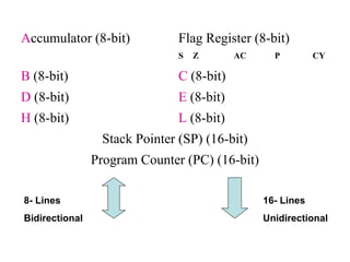
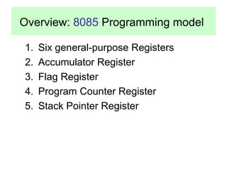
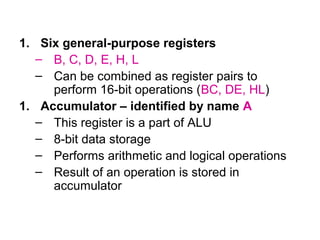
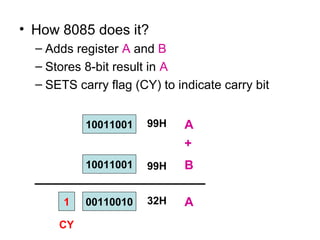
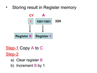
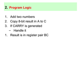
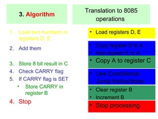
This document provides an overview of programming with the 8085 microprocessor using assembly language. It discusses the 8085 programming model including registers, flags, and addressing modes. It also covers the instruction set categories such as data transfer, arithmetic, logical, and branching operations. Examples are given of writing assembly language programs, including adding two numbers, handling results larger than 8 bits, and separating digits of a hexadecimal number. The document is intended to teach assembly language programming for the 8085 microprocessor.
![4. Addressing Modes of 8085
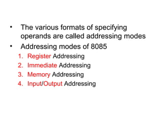
• Format of a typical Assembly language instruction
is given below-
[Label:] Mnemonic [Operands] [;comments]
HLT
MVI A, 20H
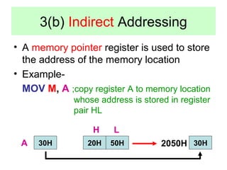
MOV M, A ;Copy A to memory location whose
address is stored in register pair HL
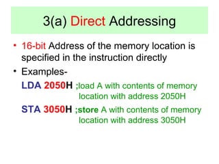
LOAD: LDA 2050H ;Load A with contents of memory
location with address 2050H
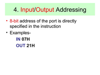
READ: IN 07H ;Read data from Input port with
address 07H](https://image.slidesharecdn.com/malpedusat-140908073741-phpapp01/85/Malp-edusat-41-320.jpg)