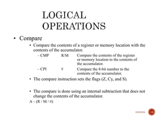
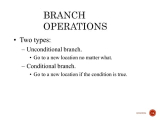
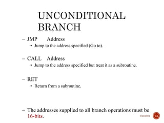
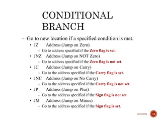
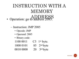
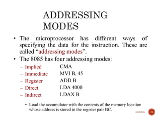
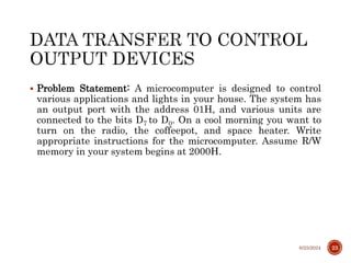
Rakesh Biswas, PhD
IIIT Guwahati
6/25/2024 2
– Since the 8085 is an 8-bit device it can have up to 28
(256) combinations.
• However, the 8085 only uses 246 combinations that represent a
total of 74 instructions.
– Most of the instructions have more than one format.
– These instructions can be grouped into five different
groups:
• Data Transfer Operations
• Arithmetic Operations
• Logic Operations
• Branch Operations
• Machine Control Operations
6/25/2024 3
• Each instruction has two parts.
– The first part is the task or operation to be
performed.
• This part is called the “opcode” (operation code).
– The second part is the data to be operated on
• Called the “operand”.
6/25/2024 4
– These operations simply COPY the data from the
source to the destination.
– MOV, MVI, LDA, and STA
– They transfer:
• Data between registers.
• Data Byte to a register or memory location.
• Data between a memory location and a register.
• Data between an IO Device and the accumulator.
– The data in the source is not changed. 6/25/2024 5
• The 8085 provides an instruction to place the 16-
bit data into the register pair in one step.
• LXI Rp, <16-bit address> (Load eXtended Immediate)
– The instruction LXI B 4000H will place the 16-bit
number 4000 into the register pair B, C.
• The upper two digits are placed in the 1st register of the pair
and the lower two digits in the 2nd .
40 00
LXI B 40 00H B C
6/25/2024 6
• Most of the instructions of the 8085 can use a
memory location in place of a register.
– The memory location will become the “memory” register M.
• MOV M B
– copy the data from register B into a memory location.
– Which memory location?
• The memory location is identified by the contents of
the HL register pair.
– The 16-bit contents of the HL register pair are treated as a
16-bit address and used to identify the memory location.
6/25/2024 7
– Addition (ADD, ADI):
– Any 8-bit number.
– The contents of a register.
– The contents of a memory location.
• Can be added to the contents of the accumulator and the result is stored
in the accumulator.
– Subtraction (SUB, SUI):
– Any 8-bit number
– The contents of a register
– The contents of a memory location
• Can be subtracted from the contents of the accumulator. The result is
stored in the accumulator.
6/25/2024 8
• These instructions perform an arithmetic operation using
the contents of a memory location while they are still in
memory.
– ADD M
• Add the contents of M to the Accumulator
– SUB M
• Sub the contents of M from the Accumulator
– INR M / DCR M
• Increment/decrement the contents of the memory location in place.
– All of these use the contents of the HL register pair to identify the
memory location being used.
6/25/2024 9
– Increment (INR) and Decrement (DCR):
• The 8-bit contents of any memory location or any
register can be directly incremented or decremented
by 1.
• No need to disturb the contents of the accumulator.
6/25/2024 10
• These instructions perform logic operations on the
contents of the accumulator.
– ANA, ANI, ORA, ORI, XRA and XRI
• Source: Accumulator and
– An 8-bit number
– The contents of a register
– The contents of a memory location
• Destination: Accumulator
ANA
ANI
R/M
#
AND Accumulator With Reg/Mem
AND Accumulator With an 8-bit number
ORA R/M OR Accumulator With Reg/Mem
ORI # OR Accumulator With an 8-bit number
XRA R/M XOR Accumulator With Reg/Mem
XRI # XOR Accumulator With an 8-bit number
6/25/2024 11
– Complement:
• 1’s complement of the contents of the accumulator.
CMA No operand
6/25/2024 12
• Compare
• Compare the contents of a register or memory location with the
contents of the accumulator.
– CMP R/M Compare the contents of the register
or memory location to the contents of
the accumulator.
– CPI # Compare the 8-bit number to the
contents of the accumulator.
• The compare instruction sets the flags (Z, Cy, and S).
• The compare is done using an internal subtraction that does not
change the contents of the accumulator.
A – (R / M / #)
6/25/2024 13
• Two types:
– Unconditional branch.
• Go to a new location no matter what.
– Conditional branch.
• Go to a new location if the condition is true.
6/25/2024 14
– JMP Address
• Jump to the address specified (Go to).
– CALL Address
• Jump to the address specified but treat it as a subroutine.
– RET
• Return from a subroutine.
– The addresses supplied to all branch operations must be
16-bits. 6/25/2024 15
– Go to new location if a specified condition is met.
• JZ Address (Jump on Zero)
– Go to address specified if the Zero flag is set.
• JNZ Address (Jump on NOT Zero)
– Go to address specified if the Zero flag is not set.
• JC Address (Jump on Carry)
– Go to the address specified if the Carry flag is set.
• JNC Address (Jump on No Carry)
– Go to the address specified if the Carry flag is not set.
• JP Address (Jump on Plus)
– Go to the address specified if the Sign flag is not set
• JM Address (Jump on Minus)
– Go to the address specified if the Sign flag is set.
6/25/2024 16
– HLT
• Stop executing the program.
– NOP
• No operation
• Exactly as it says, do nothing.
• Usually used for delay or to replace instructions
during debugging.
6/25/2024 17
• There are different ways for specifying the
operand:
– There may not be an operand (implied operand)
• CMA
– The operand may be an 8-bit number (immediate data)
• ADI 4FH
– The operand may be an internal register (register)
• SUB B
– The operand may be a 16-bit address (memory address)
• LDA 4000H
6/25/2024 18
• Depending on the operand type, the instruction
may have different sizes. It will occupy a different
number of memory bytes.
– Typically, all instructions occupy one byte only.
– The exception is any instruction that contains
immediate data or a memory address.
• Instructions that include immediate data use two bytes.
– One for the opcode and the other for the 8-bit data.
• Instructions that include a memory address occupy three bytes.
– One for the opcode, and the other two for the 16-bit address.
6/25/2024 19
• Operation: Load an 8-bit number into the
accumulator.
– MVI A, 32
• Operation: MVI A
• Operand: The number 32
• Binary Code:
0011 1110 3E 1st byte.
0011 0010 32 2nd byte.
6/25/2024 20
• Operation: go to address 2085.
– Instruction: JMP 2085
• Opcode: JMP
• Operand: 2085
• Binary code:
1100 0011 C3 1st byte.
1000 0101 85 2nd byte
0010 0000 20 3rd byte
6/25/2024 21
• The microprocessor has different ways of
specifying the data for the instruction. These are
called “addressing modes”.
• The 8085 has four addressing modes:
– Implied
– Immediate
– Register
– Direct
– Indirect
CMA
MVI B, 45
ADD B
LDA 4000
LDAX B
• Load the accumulator with the contents of the memory location
whose address is stored in the register pair BC. 6/25/2024 22
 Problem Statement: A microcomputer is designed to control
various applications and lights in your house. The system has
an output port with the address 01H, and various units are
connected to the bits D7 to D0. On a cool morning you want to
turn on the radio, the coffeepot, and space heater. Write
appropriate instructions for the microcomputer. Assume R/W
memory in your system begins at 2000H.
6/25/2024 23

MicroprocessorLecture_2_eightbit_microprocessor.ppt

  • 1.
  • 2.
  • 3.
    – Since the8085 is an 8-bit device it can have up to 28 (256) combinations. • However, the 8085 only uses 246 combinations that represent a total of 74 instructions. – Most of the instructions have more than one format. – These instructions can be grouped into five different groups: • Data Transfer Operations • Arithmetic Operations • Logic Operations • Branch Operations • Machine Control Operations 6/25/2024 3
  • 4.
    • Each instructionhas two parts. – The first part is the task or operation to be performed. • This part is called the “opcode” (operation code). – The second part is the data to be operated on • Called the “operand”. 6/25/2024 4
  • 5.
    – These operationssimply COPY the data from the source to the destination. – MOV, MVI, LDA, and STA – They transfer: • Data between registers. • Data Byte to a register or memory location. • Data between a memory location and a register. • Data between an IO Device and the accumulator. – The data in the source is not changed. 6/25/2024 5
  • 6.
    • The 8085provides an instruction to place the 16- bit data into the register pair in one step. • LXI Rp, <16-bit address> (Load eXtended Immediate) – The instruction LXI B 4000H will place the 16-bit number 4000 into the register pair B, C. • The upper two digits are placed in the 1st register of the pair and the lower two digits in the 2nd . 40 00 LXI B 40 00H B C 6/25/2024 6
  • 7.
    • Most ofthe instructions of the 8085 can use a memory location in place of a register. – The memory location will become the “memory” register M. • MOV M B – copy the data from register B into a memory location. – Which memory location? • The memory location is identified by the contents of the HL register pair. – The 16-bit contents of the HL register pair are treated as a 16-bit address and used to identify the memory location. 6/25/2024 7
  • 8.
    – Addition (ADD,ADI): – Any 8-bit number. – The contents of a register. – The contents of a memory location. • Can be added to the contents of the accumulator and the result is stored in the accumulator. – Subtraction (SUB, SUI): – Any 8-bit number – The contents of a register – The contents of a memory location • Can be subtracted from the contents of the accumulator. The result is stored in the accumulator. 6/25/2024 8
  • 9.
    • These instructionsperform an arithmetic operation using the contents of a memory location while they are still in memory. – ADD M • Add the contents of M to the Accumulator – SUB M • Sub the contents of M from the Accumulator – INR M / DCR M • Increment/decrement the contents of the memory location in place. – All of these use the contents of the HL register pair to identify the memory location being used. 6/25/2024 9
  • 10.
    – Increment (INR)and Decrement (DCR): • The 8-bit contents of any memory location or any register can be directly incremented or decremented by 1. • No need to disturb the contents of the accumulator. 6/25/2024 10
  • 11.
    • These instructionsperform logic operations on the contents of the accumulator. – ANA, ANI, ORA, ORI, XRA and XRI • Source: Accumulator and – An 8-bit number – The contents of a register – The contents of a memory location • Destination: Accumulator ANA ANI R/M # AND Accumulator With Reg/Mem AND Accumulator With an 8-bit number ORA R/M OR Accumulator With Reg/Mem ORI # OR Accumulator With an 8-bit number XRA R/M XOR Accumulator With Reg/Mem XRI # XOR Accumulator With an 8-bit number 6/25/2024 11
  • 12.
    – Complement: • 1’scomplement of the contents of the accumulator. CMA No operand 6/25/2024 12
  • 13.
    • Compare • Comparethe contents of a register or memory location with the contents of the accumulator. – CMP R/M Compare the contents of the register or memory location to the contents of the accumulator. – CPI # Compare the 8-bit number to the contents of the accumulator. • The compare instruction sets the flags (Z, Cy, and S). • The compare is done using an internal subtraction that does not change the contents of the accumulator. A – (R / M / #) 6/25/2024 13
  • 14.
    • Two types: –Unconditional branch. • Go to a new location no matter what. – Conditional branch. • Go to a new location if the condition is true. 6/25/2024 14
  • 15.
    – JMP Address •Jump to the address specified (Go to). – CALL Address • Jump to the address specified but treat it as a subroutine. – RET • Return from a subroutine. – The addresses supplied to all branch operations must be 16-bits. 6/25/2024 15
  • 16.
    – Go tonew location if a specified condition is met. • JZ Address (Jump on Zero) – Go to address specified if the Zero flag is set. • JNZ Address (Jump on NOT Zero) – Go to address specified if the Zero flag is not set. • JC Address (Jump on Carry) – Go to the address specified if the Carry flag is set. • JNC Address (Jump on No Carry) – Go to the address specified if the Carry flag is not set. • JP Address (Jump on Plus) – Go to the address specified if the Sign flag is not set • JM Address (Jump on Minus) – Go to the address specified if the Sign flag is set. 6/25/2024 16
  • 17.
    – HLT • Stopexecuting the program. – NOP • No operation • Exactly as it says, do nothing. • Usually used for delay or to replace instructions during debugging. 6/25/2024 17
  • 18.
    • There aredifferent ways for specifying the operand: – There may not be an operand (implied operand) • CMA – The operand may be an 8-bit number (immediate data) • ADI 4FH – The operand may be an internal register (register) • SUB B – The operand may be a 16-bit address (memory address) • LDA 4000H 6/25/2024 18
  • 19.
    • Depending onthe operand type, the instruction may have different sizes. It will occupy a different number of memory bytes. – Typically, all instructions occupy one byte only. – The exception is any instruction that contains immediate data or a memory address. • Instructions that include immediate data use two bytes. – One for the opcode and the other for the 8-bit data. • Instructions that include a memory address occupy three bytes. – One for the opcode, and the other two for the 16-bit address. 6/25/2024 19
  • 20.
    • Operation: Loadan 8-bit number into the accumulator. – MVI A, 32 • Operation: MVI A • Operand: The number 32 • Binary Code: 0011 1110 3E 1st byte. 0011 0010 32 2nd byte. 6/25/2024 20
  • 21.
    • Operation: goto address 2085. – Instruction: JMP 2085 • Opcode: JMP • Operand: 2085 • Binary code: 1100 0011 C3 1st byte. 1000 0101 85 2nd byte 0010 0000 20 3rd byte 6/25/2024 21
  • 22.
    • The microprocessorhas different ways of specifying the data for the instruction. These are called “addressing modes”. • The 8085 has four addressing modes: – Implied – Immediate – Register – Direct – Indirect CMA MVI B, 45 ADD B LDA 4000 LDAX B • Load the accumulator with the contents of the memory location whose address is stored in the register pair BC. 6/25/2024 22
  • 23.
     Problem Statement:A microcomputer is designed to control various applications and lights in your house. The system has an output port with the address 01H, and various units are connected to the bits D7 to D0. On a cool morning you want to turn on the radio, the coffeepot, and space heater. Write appropriate instructions for the microcomputer. Assume R/W memory in your system begins at 2000H. 6/25/2024 23