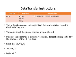
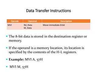
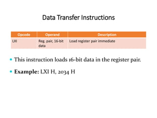
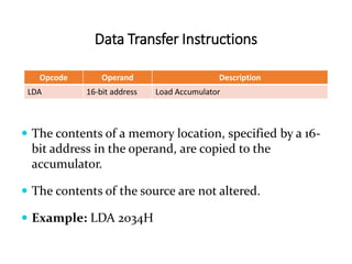
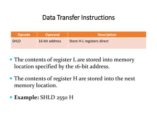
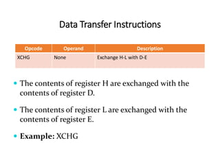
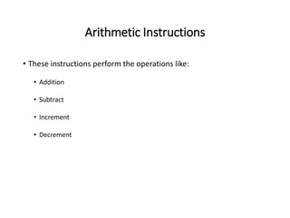
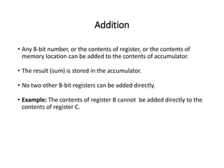
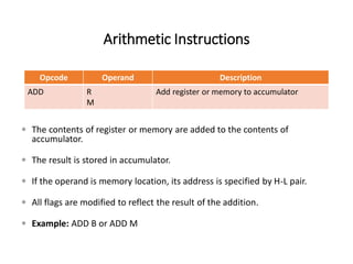
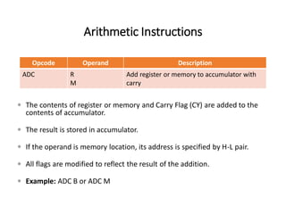
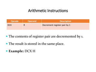
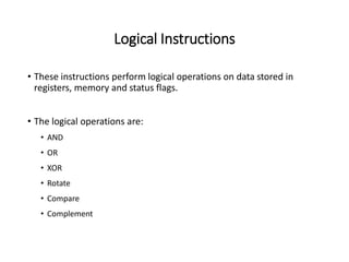
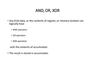
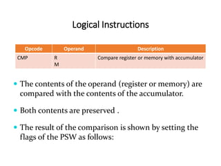
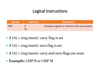
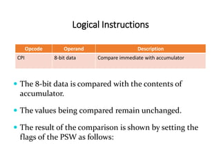
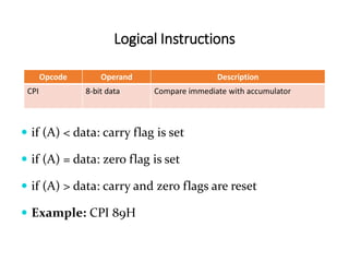
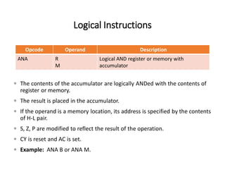
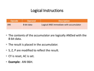
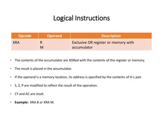
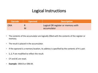
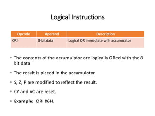
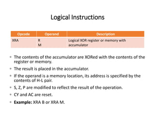
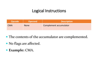
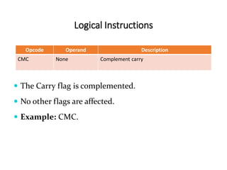
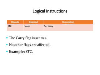
INSTRUCTION SET OF 8085
Instruction Set of 8085
 An instruction is a binary pattern designed inside a microprocessor
to perform a specific function.
 The entire group of instructions that a microprocessor supports is
called Instruction Set.
 8085 has 246 instructions.
 Each instruction is represented by an 8-bit binary value.
 These 8-bits of binary value is called Op-Code or Instruction Byte.
Classification of Instruction Set
• Data Transfer Instruction
• Arithmetic Instructions
• Logical Instructions
• Branching Instructions
• Control Instructions
Data Transfer Instructions
• These instructions move data between registers, or between
memory and registers.
• These instructions copy data from source to destination.
• While copying, the contents of source are not modified.
Data Transfer Instructions
Opcode Operand Description
MOV Rd, Rs
Rd, M
M, Rs
Copy from source to destination.
 This instruction copies the contents of the source register into the
destination register.
 The contents of the source register are not altered.
 If one of the operands is a memory location, its location is specified by
the contents of the HL registers.
 Example: MOV B, C
 MOV B, M
 MOV M, C
Data Transfer Instructions
Opcode Operand Description
MVI Rd, Data
M, Data
Move immediate 8-bit
 The 8-bit data is stored in the destination register or
memory.
 If the operand is a memory location, its location is
specified by the contents of the H-L registers.
 Example: MVI A, 57H
 MVI M, 57H
Data Transfer Instructions
Opcode Operand Description
LXI Reg. pair, 16-bit
data
Load register pair immediate
 This instruction loads 16-bit data in the register pair.
 Example: LXI H, 2034 H
Data Transfer Instructions
Opcode Operand Description
LDA 16-bit address Load Accumulator
 The contents of a memory location, specified by a 16-
bit address in the operand, are copied to the
accumulator.
 The contents of the source are not altered.
 Example: LDA 2034H
Data Transfer Instructions
Opcode Operand Description
LDAX B/D Register Pair Load accumulator indirect
 The contents of the designated register pair point to a memory
location.
 This instruction copies the contents of that memory location into
the accumulator.
 The contents of either the register pair or the memory location are
not altered.
 Example: LDAX B
Data Transfer Instructions
Opcode Operand Description
LHLD 16-bit address Load H-L registers direct
 This instruction copies the contents of memory
location pointed out by 16-bit address into register L.
 It copies the contents of next memory location into
register H.
 Example: LHLD 2040 H
Data Transfer Instructions
Opcode Operand Description
STA 16-bit address Store accumulator direct
 The contents of accumulator are copied into the
memory location specified by the operand.
 Example: STA 2500 H
Data Transfer Instructions
Opcode Operand Description
STAX Reg. pair Store accumulator indirect
 The contents of accumulator are copied into the
memory location specified by the contents of the
register pair.
 Example: STAX B
Data Transfer Instructions
Opcode Operand Description
SHLD 16-bit address Store H-L registers direct
 The contents of register L are stored into memory
location specified by the 16-bit address.
 The contents of register H are stored into the next
memory location.
 Example: SHLD 2550 H
Data Transfer Instructions
Opcode Operand Description
XCHG None Exchange H-L with D-E
 The contents of register H are exchanged with the
contents of register D.
 The contents of register L are exchanged with the
contents of register E.
 Example: XCHG
Arithmetic Instructions
• These instructions perform the operations like:
• Addition
• Subtract
• Increment
• Decrement
Addition
• Any 8-bit number, or the contents of register, or the contents of
memory location can be added to the contents of accumulator.
• The result (sum) is stored in the accumulator.
• No two other 8-bit registers can be added directly.
• Example: The contents of register B cannot be added directly to the
contents of register C.
Subtraction
• Any 8-bit number, or the contents of register, or the contents of
memory location can be subtracted from the contents of
accumulator.
• The result is stored in the accumulator.
• Subtraction is performed in 2’s complement form.
• If the result is negative, it is stored in 2’s complement form.
• No two other 8-bit registers can be subtracted directly.
Increment / Decrement
• The 8-bit contents of a register or a memory location can be
incremented or decremented by 1.
• The 16-bit contents of a register pair can be incremented or
decremented by 1.
• Increment or decrement can be performed on any register or a
memory location.
Arithmetic Instructions
Opcode Operand Description
ADD R
M
Add register or memory to accumulator
 The contents of register or memory are added to the contents of
accumulator.
 The result is stored in accumulator.
 If the operand is memory location, its address is specified by H-L pair.
 All flags are modified to reflect the result of the addition.
 Example: ADD B or ADD M
Arithmetic Instructions
Opcode Operand Description
ADC R
M
Add register or memory to accumulator with
carry
 The contents of register or memory and Carry Flag (CY) are added to the
contents of accumulator.
 The result is stored in accumulator.
 If the operand is memory location, its address is specified by H-L pair.
 All flags are modified to reflect the result of the addition.
 Example: ADC B or ADC M
Arithmetic Instructions
Opcode Operand Description
ADI 8-bit data Add immediate to accumulator
 The 8-bit data is added to the contents of accumulator.
 The result is stored in accumulator.
 All flags are modified to reflect the result of the
addition.
 Example: ADI 45 H
Arithmetic Instructions
Opcode Operand Description
ACI 8-bit data Add immediate to accumulator with carry
 The 8-bit data and the Carry Flag (CY) are added to the
contents of accumulator.
 The result is stored in accumulator.
 All flags are modified to reflect the result of the addition.
 Example: ACI 45 H
Arithmetic Instructions
Opcode Operand Description
DAD Reg. pair Add register pair to H-L pair
 The 16-bit contents of the register pair are added to the
contents of H-L pair.
 The result is stored in H-L pair.
 If the result is larger than 16 bits, then CY is set.
 No other flags are changed.
 Example: DAD B
Arithmetic Instructions
Opcode Operand Description
SUB R
M
Subtract register or memory from accumulator
 The contents of the register or memory location are subtracted from the
contents of the accumulator.
 The result is stored in accumulator.
 If the operand is memory location, its address is specified by H-L pair.
 All flags are modified to reflect the result of subtraction.
 Example: SUB B or SUB M
Arithmetic Instructions
Opcode Operand Description
SBB R
M
Subtract register or memory from accumulator
with borrow
 The contents of the register or memory location and Borrow Flag (i.e. CY)
are subtracted from the contents of the accumulator.
 The result is stored in accumulator.
 If the operand is memory location, its address is specified by H-L pair.
 All flags are modified to reflect the result of subtraction.
 Example: SBB B or SBB M
Arithmetic Instructions
Opcode Operand Description
SUI 8-bit data Subtract immediate from accumulator
 The 8-bit data is subtracted from the contents of the
accumulator.
 The result is stored in accumulator.
 All flags are modified to reflect the result of subtraction.
 Example: SUI 45 H
Arithmetic Instructions
Opcode Operand Description
SBI 8-bit data Subtract immediate from accumulator with
borrow
 The 8-bit data and the Borrow Flag (i.e. CY) is subtracted
from the contents of the accumulator.
 The result is stored in accumulator.
 All flags are modified to reflect the result of subtraction.
 Example: SBI 45 H
Arithmetic Instructions
Opcode Operand Description
INR R
M
Increment register or memory by 1
 The contents of register or memory location are incremented
by 1.
 The result is stored in the same place.
 If the operand is a memory location, its address is specified by
the contents of H-L pair.
 Example: INR B or INR M
Arithmetic Instructions
Opcode Operand Description
INX R Increment register pair by 1
 The contents of register pair are incremented by 1.
 The result is stored in the same place.
 Example: INX H
Arithmetic Instructions
Opcode Operand Description
DCR R
M
Decrement register or memory by 1
 The contents of register or memory location are decremented
by 1.
 The result is stored in the same place.
 If the operand is a memory location, its address is specified by
the contents of H-L pair.
 Example: DCR B or DCR M
Arithmetic Instructions
Opcode Operand Description
DCX R Decrement register pair by 1
 The contents of register pair are decremented by 1.
 The result is stored in the same place.
 Example: DCX H
Logical Instructions
• These instructions perform logical operations on data stored in
registers, memory and status flags.
• The logical operations are:
• AND
• OR
• XOR
• Rotate
• Compare
• Complement
AND, OR, XOR
• Any 8-bit data, or the contents of register, or memory location can
logically have
• AND operation
• OR operation
• XOR operation
with the contents of accumulator.
• The result is stored in accumulator.
Rotate
• Each bit in the accumulator can be shifted either left or right to the
next position.
Compare
• Any 8-bit data, or the contents of register, or memory location can be
compares for:
• Equality
• Greater Than
• Less Than
with the contents of accumulator.
• The result is reflected in status flags.
Complement
• The contents of accumulator can be complemented.
• Each 0 is replaced by 1 and each 1 is replaced by 0.
Logical Instructions
Opcode Operand Description
CMP R
M
Compare register or memory with accumulator
 The contents of the operand (register or memory) are
compared with the contents of the accumulator.
 Both contents are preserved .
 The result of the comparison is shown by setting the
flags of the PSW as follows:
Logical Instructions
Opcode Operand Description
CMP R
M
Compare register or memory with accumulator
 if (A) < (reg/mem): carry flag is set
 if (A) = (reg/mem): zero flag is set
 if (A) > (reg/mem): carry and zero flags are reset.
 Example: CMP B or CMP M
Logical Instructions
Opcode Operand Description
CPI 8-bit data Compare immediate with accumulator
 The 8-bit data is compared with the contents of
accumulator.
 The values being compared remain unchanged.
 The result of the comparison is shown by setting the
flags of the PSW as follows:
Logical Instructions
Opcode Operand Description
CPI 8-bit data Compare immediate with accumulator
 if (A) < data: carry flag is set
 if (A) = data: zero flag is set
 if (A) > data: carry and zero flags are reset
 Example: CPI 89H
Logical Instructions
Opcode Operand Description
ANA R
M
Logical AND register or memory with
accumulator
 The contents of the accumulator are logically ANDed with the contents of
register or memory.
 The result is placed in the accumulator.
 If the operand is a memory location, its address is specified by the contents
of H-L pair.
 S, Z, P are modified to reflect the result of the operation.
 CY is reset and AC is set.
 Example: ANA B or ANA M.
Logical Instructions
Opcode Operand Description
ANI 8-bit data Logical AND immediate with accumulator
 The contents of the accumulator are logically ANDed with the
8-bit data.
 The result is placed in the accumulator.
 S, Z, P are modified to reflect the result.
 CY is reset, AC is set.
 Example: ANI 86H.
Logical Instructions
Opcode Operand Description
XRA R
M
Exclusive OR register or memory with
accumulator
 The contents of the accumulator are XORed with the contents of the register or memory.
 The result is placed in the accumulator.
 If the operand is a memory location, its address is specified by the contents of H-L pair.
 S, Z, P are modified to reflect the result of the operation.
 CY and AC are reset.
 Example: XRA B or XRA M.
Logical Instructions
Opcode Operand Description
ORA R
M
Logical OR register or memory with
accumulator
 The contents of the accumulator are logically ORed with the contents of the register or
memory.
 The result is placed in the accumulator.
 If the operand is a memory location, its address is specified by the contents of H-L pair.
 S, Z, P are modified to reflect the result.
 CY and AC are reset.
 Example: ORA B or ORA M.
Logical Instructions
Opcode Operand Description
ORI 8-bit data Logical OR immediate with accumulator
 The contents of the accumulator are logically ORed with the 8-
bit data.
 The result is placed in the accumulator.
 S, Z, P are modified to reflect the result.
 CY and AC are reset.
 Example: ORI 86H.
Logical Instructions
Opcode Operand Description
XRA R
M
Logical XOR register or memory with
accumulator
 The contents of the accumulator are XORed with the contents of the
register or memory.
 The result is placed in the accumulator.
 If the operand is a memory location, its address is specified by the
contents of H-L pair.
 S, Z, P are modified to reflect the result of the operation.
 CY and AC are reset.
 Example: XRA B or XRA M.
Logical Instructions
Opcode Operand Description
XRI 8-bit data XOR immediate with accumulator
 The contents of the accumulator are XORed with the
8-bit data.
 The result is placed in the accumulator.
 S, Z, P are modified to reflect the result.
 CY and AC are reset.
 Example: XRI 86H.
Logical Instructions
Opcode Operand Description
RLC None Rotate accumulator left
 Each binary bit of the accumulator is rotated left by one
position.
 Bit D7 is placed in the position of D0 as well as in the Carry
flag.
 CY is modified according to bit D7.
 S, Z, P, AC are not affected.
 Example: RLC.
Logical Instructions
Opcode Operand Description
RRC None Rotate accumulator right
 Each binary bit of the accumulator is rotated right by one
position.
 Bit D0 is placed in the position of D7 as well as in the Carry
flag.
 CY is modified according to bit D0.
 S, Z, P, AC are not affected.
 Example: RRC.
Logical Instructions
Opcode Operand Description
RAL None Rotate accumulator left through carry
 Each binary bit of the accumulator is rotated left by one
position through the Carry flag.
 Bit D7 is placed in the Carry flag, and the Carry flag is placed in
the least significant position D0.
 CY is modified according to bit D7.
 S, Z, P, AC are not affected.
 Example: RAL.
Logical Instructions
Opcode Operand Description
RAR None Rotate accumulator right through carry
 Each binary bit of the accumulator is rotated right by one
position through the Carry flag.
 Bit D0 is placed in the Carry flag, and the Carry flag is placed in
the most significant position D7.
 CY is modified according to bit D0.
 S, Z, P, AC are not affected.
 Example: RAR.
Logical Instructions
Opcode Operand Description
CMA None Complement accumulator
 The contents of the accumulator are complemented.
 No flags are affected.
 Example: CMA.
Logical Instructions
Opcode Operand Description
CMC None Complement carry
 The Carry flag is complemented.
 No other flags are affected.
 Example: CMC.
Logical Instructions
Opcode Operand Description
STC None Set carry
 The Carry flag is set to 1.
 No other flags are affected.
 Example: STC.
Branching Instructions
• The branching instruction alter the normal sequential flow.
• These instructions alter either unconditionally or conditionally.
Branching Instructions
Opcode Operand Description
JMP 16-bit address Jump unconditionally
 The program sequence is transferred to the memory
location specified by the 16-bit address given in the
operand.
 Example: JMP 2034 H.
Branching Instructions
Opcode Operand Description
Jx 16-bit address Jump conditionally
 The program sequence is transferred to the memory
location specified by the 16-bit address given in the
operand based on the specified flag of the PSW.
 Example: JZ 2034 H.
Jump Conditionally
Opcode Description Status Flags
JC Jump if Carry CY = 1
JNC Jump if No Carry CY = 0
JP Jump if Positive S = 0
JM Jump if Minus S = 1
JZ Jump if Zero Z = 1
JNZ Jump if No Zero Z = 0
JPE Jump if Parity Even P = 1
JPO Jump if Parity Odd P = 0
Branching Instructions
Opcode Operand Description
CALL 16-bit address Call unconditionally
 The program sequence is transferred to the memory
location specified by the 16-bit address given in the
operand.
 Before the transfer, the address of the next instruction after
CALL (the contents of the program counter) is pushed onto
the stack.
 Example: CALL 2034 H.
Branching Instructions
Opcode Operand Description
Cx 16-bit address Call conditionally
 The program sequence is transferred to the memory
location specified by the 16-bit address given in the
operand based on the specified flag of the PSW.
 Before the transfer, the address of the next instruction
after the call (the contents of the program counter) is
pushed onto the stack.
 Example: CZ 2034 H.
Call Conditionally
Opcode Description Status Flags
CC Call if Carry CY = 1
CNC Call if No Carry CY = 0
CP Call if Positive S = 0
CM Call if Minus S = 1
CZ Call if Zero Z = 1
CNZ Call if No Zero Z = 0
CPE Call if Parity Even P = 1
CPO Call if Parity Odd P = 0
Branching Instructions
Opcode Operand Description
RET None Return unconditionally
 The program sequence is transferred from the
subroutine to the calling program.
 The two bytes from the top of the stack are copied into
the program counter, and program execution begins at
the new address.
 Example: RET.
Branching Instructions
Opcode Operand Description
Rx None Call conditionally
 The program sequence is transferred from the
subroutine to the calling program based on the
specified flag of the PSW.
 The two bytes from the top of the stack are copied into
the program counter, and program execution begins at
the new address.
 Example: RZ.
Return Conditionally
Opcode Description Status Flags
RC Return if Carry CY = 1
RNC Return if No Carry CY = 0
RP Return if Positive S = 0
RM Return if Minus S = 1
RZ Return if Zero Z = 1
RNZ Return if No Zero Z = 0
RPE Return if Parity Even P = 1
RPO Return if Parity Odd P = 0
Branching Instructions
Opcode Operand Description
RST 0 – 7 Restart (Software Interrupts)
 The RST instruction jumps the control to one of eight
memory locations depending upon the number.
 These are used as software instructions in a program to
transfer program execution to one of the eight
locations.
 Example: RST 3.
Restart Address Table
Instructions Restart Address
RST 0 0000 H
RST 1 0008 H
RST 2 0010 H
RST 3 0018 H
RST 4 0020 H
RST 5 0028 H
RST 6 0030 H
RST 7 0038 H
Control Instructions
• The control instructions control the operation of microprocessor.
Control Instructions
Opcode Operand Description
NOP None No operation
 No operation is performed.
 The instruction is fetched and decoded but no
operation is executed.
 Example: NOP
Control Instructions
Opcode Operand Description
HLT None Halt
 The CPU finishes executing the current instruction
and halts any further execution.
 An interrupt or reset is necessary to exit from the halt
state.
 Example: HLT
Control Instructions
Opcode Operand Description
DI None Disable interrupt
 The interrupt enable flip-flop is reset and all the
interrupts except the TRAP are disabled.
 No flags are affected.
 Example: DI
Control Instructions
Opcode Operand Description
EI None Enable interrupt
 The interrupt enable flip-flop is set and all interrupts
are enabled.
 No flags are affected.
 This instruction is necessary to re-enable the
interrupts (except TRAP).
 Example: EI
Control Instructions
Opcode Operand Description
RIM None Read Interrupt Mask
 This is a multipurpose instruction used to read the
status of interrupts 7.5, 6.5, 5.5 and read serial data
input bit.
 The instruction loads eight bits in the accumulator
with the following interpretations.
 Example: RIM
RIM Instruction
Control Instructions
Opcode Operand Description
SIM None Set Interrupt Mask
 This is a multipurpose instruction and used to
implement the 8085 interrupts 7.5, 6.5, 5.5, and serial
data output.
 The instruction interprets the accumulator contents as
follows.
 Example: SIM
SIM Instruction

8085 Instructions.pdf

  • 1.
  • 2.
    Instruction Set of8085  An instruction is a binary pattern designed inside a microprocessor to perform a specific function.  The entire group of instructions that a microprocessor supports is called Instruction Set.  8085 has 246 instructions.  Each instruction is represented by an 8-bit binary value.  These 8-bits of binary value is called Op-Code or Instruction Byte.
  • 3.
    Classification of InstructionSet • Data Transfer Instruction • Arithmetic Instructions • Logical Instructions • Branching Instructions • Control Instructions
  • 4.
    Data Transfer Instructions •These instructions move data between registers, or between memory and registers. • These instructions copy data from source to destination. • While copying, the contents of source are not modified.
  • 5.
    Data Transfer Instructions OpcodeOperand Description MOV Rd, Rs Rd, M M, Rs Copy from source to destination.  This instruction copies the contents of the source register into the destination register.  The contents of the source register are not altered.  If one of the operands is a memory location, its location is specified by the contents of the HL registers.  Example: MOV B, C  MOV B, M  MOV M, C
  • 6.
    Data Transfer Instructions OpcodeOperand Description MVI Rd, Data M, Data Move immediate 8-bit  The 8-bit data is stored in the destination register or memory.  If the operand is a memory location, its location is specified by the contents of the H-L registers.  Example: MVI A, 57H  MVI M, 57H
  • 7.
    Data Transfer Instructions OpcodeOperand Description LXI Reg. pair, 16-bit data Load register pair immediate  This instruction loads 16-bit data in the register pair.  Example: LXI H, 2034 H
  • 8.
    Data Transfer Instructions OpcodeOperand Description LDA 16-bit address Load Accumulator  The contents of a memory location, specified by a 16- bit address in the operand, are copied to the accumulator.  The contents of the source are not altered.  Example: LDA 2034H
  • 9.
    Data Transfer Instructions OpcodeOperand Description LDAX B/D Register Pair Load accumulator indirect  The contents of the designated register pair point to a memory location.  This instruction copies the contents of that memory location into the accumulator.  The contents of either the register pair or the memory location are not altered.  Example: LDAX B
  • 10.
    Data Transfer Instructions OpcodeOperand Description LHLD 16-bit address Load H-L registers direct  This instruction copies the contents of memory location pointed out by 16-bit address into register L.  It copies the contents of next memory location into register H.  Example: LHLD 2040 H
  • 11.
    Data Transfer Instructions OpcodeOperand Description STA 16-bit address Store accumulator direct  The contents of accumulator are copied into the memory location specified by the operand.  Example: STA 2500 H
  • 12.
    Data Transfer Instructions OpcodeOperand Description STAX Reg. pair Store accumulator indirect  The contents of accumulator are copied into the memory location specified by the contents of the register pair.  Example: STAX B
  • 13.
    Data Transfer Instructions OpcodeOperand Description SHLD 16-bit address Store H-L registers direct  The contents of register L are stored into memory location specified by the 16-bit address.  The contents of register H are stored into the next memory location.  Example: SHLD 2550 H
  • 14.
    Data Transfer Instructions OpcodeOperand Description XCHG None Exchange H-L with D-E  The contents of register H are exchanged with the contents of register D.  The contents of register L are exchanged with the contents of register E.  Example: XCHG
  • 15.
    Arithmetic Instructions • Theseinstructions perform the operations like: • Addition • Subtract • Increment • Decrement
  • 16.
    Addition • Any 8-bitnumber, or the contents of register, or the contents of memory location can be added to the contents of accumulator. • The result (sum) is stored in the accumulator. • No two other 8-bit registers can be added directly. • Example: The contents of register B cannot be added directly to the contents of register C.
  • 17.
    Subtraction • Any 8-bitnumber, or the contents of register, or the contents of memory location can be subtracted from the contents of accumulator. • The result is stored in the accumulator. • Subtraction is performed in 2’s complement form. • If the result is negative, it is stored in 2’s complement form. • No two other 8-bit registers can be subtracted directly.
  • 18.
    Increment / Decrement •The 8-bit contents of a register or a memory location can be incremented or decremented by 1. • The 16-bit contents of a register pair can be incremented or decremented by 1. • Increment or decrement can be performed on any register or a memory location.
  • 19.
    Arithmetic Instructions Opcode OperandDescription ADD R M Add register or memory to accumulator  The contents of register or memory are added to the contents of accumulator.  The result is stored in accumulator.  If the operand is memory location, its address is specified by H-L pair.  All flags are modified to reflect the result of the addition.  Example: ADD B or ADD M
  • 20.
    Arithmetic Instructions Opcode OperandDescription ADC R M Add register or memory to accumulator with carry  The contents of register or memory and Carry Flag (CY) are added to the contents of accumulator.  The result is stored in accumulator.  If the operand is memory location, its address is specified by H-L pair.  All flags are modified to reflect the result of the addition.  Example: ADC B or ADC M
  • 21.
    Arithmetic Instructions Opcode OperandDescription ADI 8-bit data Add immediate to accumulator  The 8-bit data is added to the contents of accumulator.  The result is stored in accumulator.  All flags are modified to reflect the result of the addition.  Example: ADI 45 H
  • 22.
    Arithmetic Instructions Opcode OperandDescription ACI 8-bit data Add immediate to accumulator with carry  The 8-bit data and the Carry Flag (CY) are added to the contents of accumulator.  The result is stored in accumulator.  All flags are modified to reflect the result of the addition.  Example: ACI 45 H
  • 23.
    Arithmetic Instructions Opcode OperandDescription DAD Reg. pair Add register pair to H-L pair  The 16-bit contents of the register pair are added to the contents of H-L pair.  The result is stored in H-L pair.  If the result is larger than 16 bits, then CY is set.  No other flags are changed.  Example: DAD B
  • 24.
    Arithmetic Instructions Opcode OperandDescription SUB R M Subtract register or memory from accumulator  The contents of the register or memory location are subtracted from the contents of the accumulator.  The result is stored in accumulator.  If the operand is memory location, its address is specified by H-L pair.  All flags are modified to reflect the result of subtraction.  Example: SUB B or SUB M
  • 25.
    Arithmetic Instructions Opcode OperandDescription SBB R M Subtract register or memory from accumulator with borrow  The contents of the register or memory location and Borrow Flag (i.e. CY) are subtracted from the contents of the accumulator.  The result is stored in accumulator.  If the operand is memory location, its address is specified by H-L pair.  All flags are modified to reflect the result of subtraction.  Example: SBB B or SBB M
  • 26.
    Arithmetic Instructions Opcode OperandDescription SUI 8-bit data Subtract immediate from accumulator  The 8-bit data is subtracted from the contents of the accumulator.  The result is stored in accumulator.  All flags are modified to reflect the result of subtraction.  Example: SUI 45 H
  • 27.
    Arithmetic Instructions Opcode OperandDescription SBI 8-bit data Subtract immediate from accumulator with borrow  The 8-bit data and the Borrow Flag (i.e. CY) is subtracted from the contents of the accumulator.  The result is stored in accumulator.  All flags are modified to reflect the result of subtraction.  Example: SBI 45 H
  • 28.
    Arithmetic Instructions Opcode OperandDescription INR R M Increment register or memory by 1  The contents of register or memory location are incremented by 1.  The result is stored in the same place.  If the operand is a memory location, its address is specified by the contents of H-L pair.  Example: INR B or INR M
  • 29.
    Arithmetic Instructions Opcode OperandDescription INX R Increment register pair by 1  The contents of register pair are incremented by 1.  The result is stored in the same place.  Example: INX H
  • 30.
    Arithmetic Instructions Opcode OperandDescription DCR R M Decrement register or memory by 1  The contents of register or memory location are decremented by 1.  The result is stored in the same place.  If the operand is a memory location, its address is specified by the contents of H-L pair.  Example: DCR B or DCR M
  • 31.
    Arithmetic Instructions Opcode OperandDescription DCX R Decrement register pair by 1  The contents of register pair are decremented by 1.  The result is stored in the same place.  Example: DCX H
  • 32.
    Logical Instructions • Theseinstructions perform logical operations on data stored in registers, memory and status flags. • The logical operations are: • AND • OR • XOR • Rotate • Compare • Complement
  • 33.
    AND, OR, XOR •Any 8-bit data, or the contents of register, or memory location can logically have • AND operation • OR operation • XOR operation with the contents of accumulator. • The result is stored in accumulator.
  • 34.
    Rotate • Each bitin the accumulator can be shifted either left or right to the next position.
  • 35.
    Compare • Any 8-bitdata, or the contents of register, or memory location can be compares for: • Equality • Greater Than • Less Than with the contents of accumulator. • The result is reflected in status flags.
  • 36.
    Complement • The contentsof accumulator can be complemented. • Each 0 is replaced by 1 and each 1 is replaced by 0.
  • 37.
    Logical Instructions Opcode OperandDescription CMP R M Compare register or memory with accumulator  The contents of the operand (register or memory) are compared with the contents of the accumulator.  Both contents are preserved .  The result of the comparison is shown by setting the flags of the PSW as follows:
  • 38.
    Logical Instructions Opcode OperandDescription CMP R M Compare register or memory with accumulator  if (A) < (reg/mem): carry flag is set  if (A) = (reg/mem): zero flag is set  if (A) > (reg/mem): carry and zero flags are reset.  Example: CMP B or CMP M
  • 39.
    Logical Instructions Opcode OperandDescription CPI 8-bit data Compare immediate with accumulator  The 8-bit data is compared with the contents of accumulator.  The values being compared remain unchanged.  The result of the comparison is shown by setting the flags of the PSW as follows:
  • 40.
    Logical Instructions Opcode OperandDescription CPI 8-bit data Compare immediate with accumulator  if (A) < data: carry flag is set  if (A) = data: zero flag is set  if (A) > data: carry and zero flags are reset  Example: CPI 89H
  • 41.
    Logical Instructions Opcode OperandDescription ANA R M Logical AND register or memory with accumulator  The contents of the accumulator are logically ANDed with the contents of register or memory.  The result is placed in the accumulator.  If the operand is a memory location, its address is specified by the contents of H-L pair.  S, Z, P are modified to reflect the result of the operation.  CY is reset and AC is set.  Example: ANA B or ANA M.
  • 42.
    Logical Instructions Opcode OperandDescription ANI 8-bit data Logical AND immediate with accumulator  The contents of the accumulator are logically ANDed with the 8-bit data.  The result is placed in the accumulator.  S, Z, P are modified to reflect the result.  CY is reset, AC is set.  Example: ANI 86H.
  • 43.
    Logical Instructions Opcode OperandDescription XRA R M Exclusive OR register or memory with accumulator  The contents of the accumulator are XORed with the contents of the register or memory.  The result is placed in the accumulator.  If the operand is a memory location, its address is specified by the contents of H-L pair.  S, Z, P are modified to reflect the result of the operation.  CY and AC are reset.  Example: XRA B or XRA M.
  • 44.
    Logical Instructions Opcode OperandDescription ORA R M Logical OR register or memory with accumulator  The contents of the accumulator are logically ORed with the contents of the register or memory.  The result is placed in the accumulator.  If the operand is a memory location, its address is specified by the contents of H-L pair.  S, Z, P are modified to reflect the result.  CY and AC are reset.  Example: ORA B or ORA M.
  • 45.
    Logical Instructions Opcode OperandDescription ORI 8-bit data Logical OR immediate with accumulator  The contents of the accumulator are logically ORed with the 8- bit data.  The result is placed in the accumulator.  S, Z, P are modified to reflect the result.  CY and AC are reset.  Example: ORI 86H.
  • 46.
    Logical Instructions Opcode OperandDescription XRA R M Logical XOR register or memory with accumulator  The contents of the accumulator are XORed with the contents of the register or memory.  The result is placed in the accumulator.  If the operand is a memory location, its address is specified by the contents of H-L pair.  S, Z, P are modified to reflect the result of the operation.  CY and AC are reset.  Example: XRA B or XRA M.
  • 47.
    Logical Instructions Opcode OperandDescription XRI 8-bit data XOR immediate with accumulator  The contents of the accumulator are XORed with the 8-bit data.  The result is placed in the accumulator.  S, Z, P are modified to reflect the result.  CY and AC are reset.  Example: XRI 86H.
  • 48.
    Logical Instructions Opcode OperandDescription RLC None Rotate accumulator left  Each binary bit of the accumulator is rotated left by one position.  Bit D7 is placed in the position of D0 as well as in the Carry flag.  CY is modified according to bit D7.  S, Z, P, AC are not affected.  Example: RLC.
  • 49.
    Logical Instructions Opcode OperandDescription RRC None Rotate accumulator right  Each binary bit of the accumulator is rotated right by one position.  Bit D0 is placed in the position of D7 as well as in the Carry flag.  CY is modified according to bit D0.  S, Z, P, AC are not affected.  Example: RRC.
  • 50.
    Logical Instructions Opcode OperandDescription RAL None Rotate accumulator left through carry  Each binary bit of the accumulator is rotated left by one position through the Carry flag.  Bit D7 is placed in the Carry flag, and the Carry flag is placed in the least significant position D0.  CY is modified according to bit D7.  S, Z, P, AC are not affected.  Example: RAL.
  • 51.
    Logical Instructions Opcode OperandDescription RAR None Rotate accumulator right through carry  Each binary bit of the accumulator is rotated right by one position through the Carry flag.  Bit D0 is placed in the Carry flag, and the Carry flag is placed in the most significant position D7.  CY is modified according to bit D0.  S, Z, P, AC are not affected.  Example: RAR.
  • 52.
    Logical Instructions Opcode OperandDescription CMA None Complement accumulator  The contents of the accumulator are complemented.  No flags are affected.  Example: CMA.
  • 53.
    Logical Instructions Opcode OperandDescription CMC None Complement carry  The Carry flag is complemented.  No other flags are affected.  Example: CMC.
  • 54.
    Logical Instructions Opcode OperandDescription STC None Set carry  The Carry flag is set to 1.  No other flags are affected.  Example: STC.
  • 55.
    Branching Instructions • Thebranching instruction alter the normal sequential flow. • These instructions alter either unconditionally or conditionally.
  • 56.
    Branching Instructions Opcode OperandDescription JMP 16-bit address Jump unconditionally  The program sequence is transferred to the memory location specified by the 16-bit address given in the operand.  Example: JMP 2034 H.
  • 57.
    Branching Instructions Opcode OperandDescription Jx 16-bit address Jump conditionally  The program sequence is transferred to the memory location specified by the 16-bit address given in the operand based on the specified flag of the PSW.  Example: JZ 2034 H.
  • 58.
    Jump Conditionally Opcode DescriptionStatus Flags JC Jump if Carry CY = 1 JNC Jump if No Carry CY = 0 JP Jump if Positive S = 0 JM Jump if Minus S = 1 JZ Jump if Zero Z = 1 JNZ Jump if No Zero Z = 0 JPE Jump if Parity Even P = 1 JPO Jump if Parity Odd P = 0
  • 59.
    Branching Instructions Opcode OperandDescription CALL 16-bit address Call unconditionally  The program sequence is transferred to the memory location specified by the 16-bit address given in the operand.  Before the transfer, the address of the next instruction after CALL (the contents of the program counter) is pushed onto the stack.  Example: CALL 2034 H.
  • 60.
    Branching Instructions Opcode OperandDescription Cx 16-bit address Call conditionally  The program sequence is transferred to the memory location specified by the 16-bit address given in the operand based on the specified flag of the PSW.  Before the transfer, the address of the next instruction after the call (the contents of the program counter) is pushed onto the stack.  Example: CZ 2034 H.
  • 61.
    Call Conditionally Opcode DescriptionStatus Flags CC Call if Carry CY = 1 CNC Call if No Carry CY = 0 CP Call if Positive S = 0 CM Call if Minus S = 1 CZ Call if Zero Z = 1 CNZ Call if No Zero Z = 0 CPE Call if Parity Even P = 1 CPO Call if Parity Odd P = 0
  • 62.
    Branching Instructions Opcode OperandDescription RET None Return unconditionally  The program sequence is transferred from the subroutine to the calling program.  The two bytes from the top of the stack are copied into the program counter, and program execution begins at the new address.  Example: RET.
  • 63.
    Branching Instructions Opcode OperandDescription Rx None Call conditionally  The program sequence is transferred from the subroutine to the calling program based on the specified flag of the PSW.  The two bytes from the top of the stack are copied into the program counter, and program execution begins at the new address.  Example: RZ.
  • 64.
    Return Conditionally Opcode DescriptionStatus Flags RC Return if Carry CY = 1 RNC Return if No Carry CY = 0 RP Return if Positive S = 0 RM Return if Minus S = 1 RZ Return if Zero Z = 1 RNZ Return if No Zero Z = 0 RPE Return if Parity Even P = 1 RPO Return if Parity Odd P = 0
  • 65.
    Branching Instructions Opcode OperandDescription RST 0 – 7 Restart (Software Interrupts)  The RST instruction jumps the control to one of eight memory locations depending upon the number.  These are used as software instructions in a program to transfer program execution to one of the eight locations.  Example: RST 3.
  • 66.
    Restart Address Table InstructionsRestart Address RST 0 0000 H RST 1 0008 H RST 2 0010 H RST 3 0018 H RST 4 0020 H RST 5 0028 H RST 6 0030 H RST 7 0038 H
  • 67.
    Control Instructions • Thecontrol instructions control the operation of microprocessor.
  • 68.
    Control Instructions Opcode OperandDescription NOP None No operation  No operation is performed.  The instruction is fetched and decoded but no operation is executed.  Example: NOP
  • 69.
    Control Instructions Opcode OperandDescription HLT None Halt  The CPU finishes executing the current instruction and halts any further execution.  An interrupt or reset is necessary to exit from the halt state.  Example: HLT
  • 70.
    Control Instructions Opcode OperandDescription DI None Disable interrupt  The interrupt enable flip-flop is reset and all the interrupts except the TRAP are disabled.  No flags are affected.  Example: DI
  • 71.
    Control Instructions Opcode OperandDescription EI None Enable interrupt  The interrupt enable flip-flop is set and all interrupts are enabled.  No flags are affected.  This instruction is necessary to re-enable the interrupts (except TRAP).  Example: EI
  • 72.
    Control Instructions Opcode OperandDescription RIM None Read Interrupt Mask  This is a multipurpose instruction used to read the status of interrupts 7.5, 6.5, 5.5 and read serial data input bit.  The instruction loads eight bits in the accumulator with the following interpretations.  Example: RIM
  • 73.
  • 74.
    Control Instructions Opcode OperandDescription SIM None Set Interrupt Mask  This is a multipurpose instruction and used to implement the 8085 interrupts 7.5, 6.5, 5.5, and serial data output.  The instruction interprets the accumulator contents as follows.  Example: SIM
  • 75.