The document discusses the 8085 microprocessor instruction set and addressing modes. It contains the following key points:
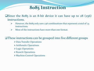
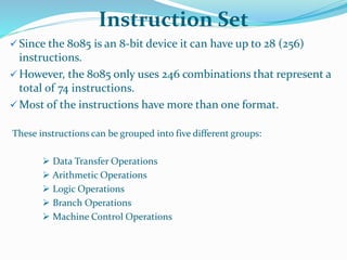
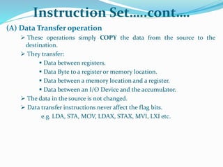
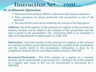
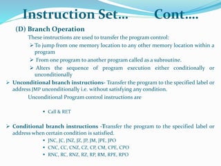
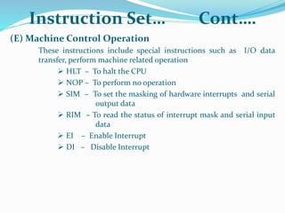
1) The 8085 has 74 instructions that are grouped into 5 categories - data transfer, arithmetic, logical, branch, and machine control operations. Most instructions have multiple formats.
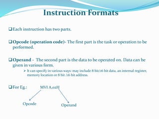
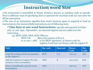
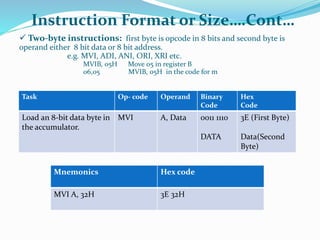
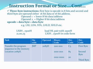
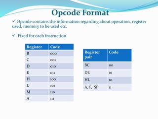
2) Instructions are 1, 2, or 3 bytes in size depending on the operands. The opcode specifies the operation and registers while the operands provide data or addresses.
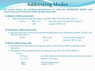
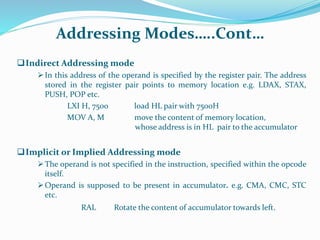
3) There are 5 addressing modes including register, immediate, direct, indirect, and implied that specify how operands are addressed in memory.
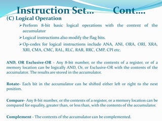
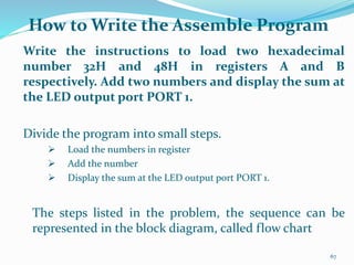
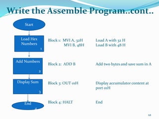
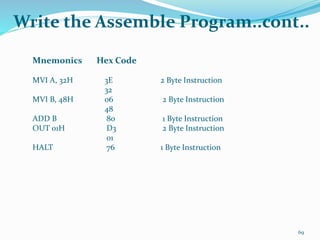
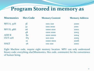
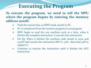
4) A sample program is provided to add two numbers and display the result using MVI, ADD, and