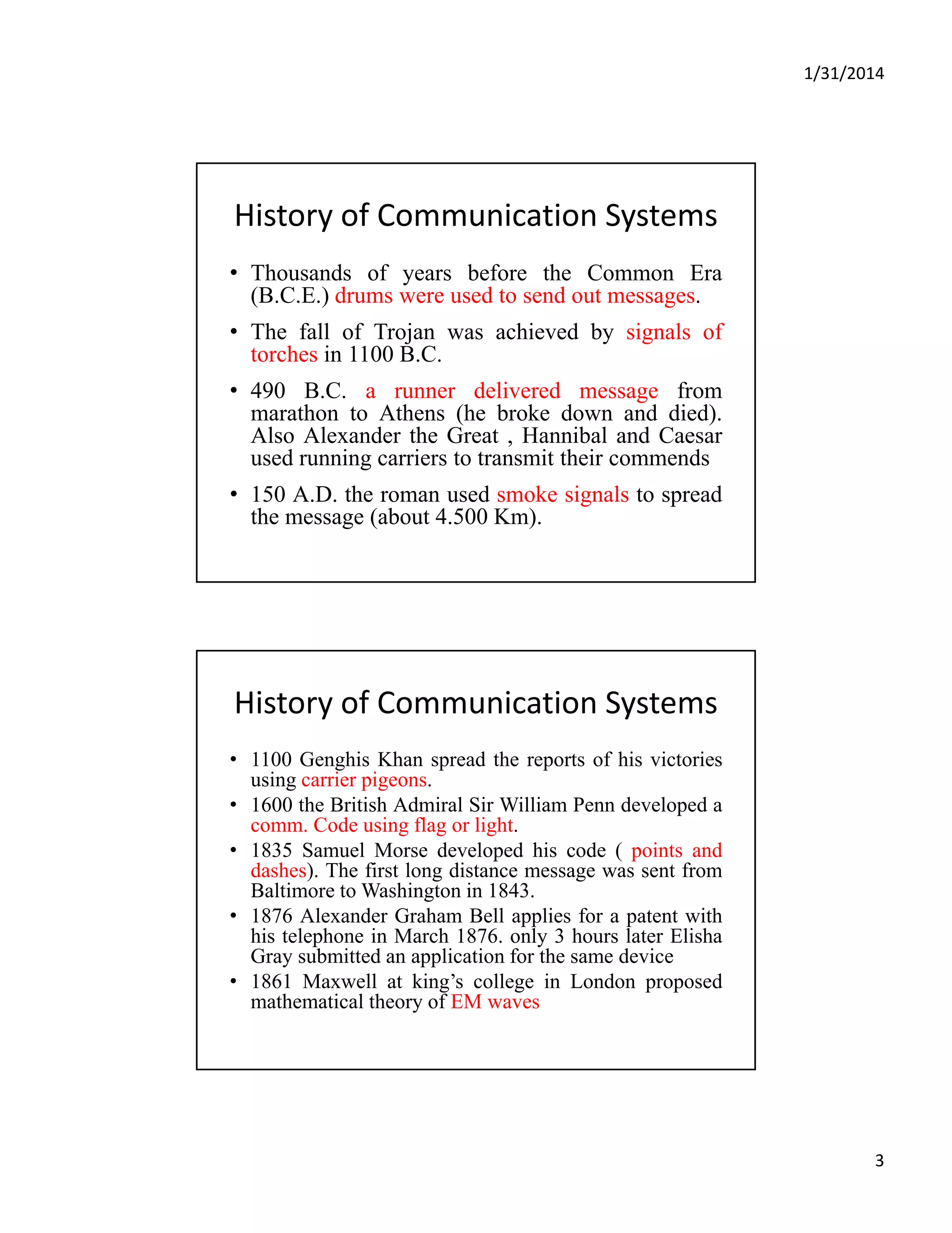
1/31/2014
1
Communication Systems
Instructor: Engr. Dr. Sarmad Ullah Khan
Assistant ProfessorAssistant Professor
Electrical Engineering Department
CECOS University of IT and Emerging Sciences
Sarmad@cecos.edu.pk
Course Objectives
To develop the basic concepts of communication systems
Text Book
Communication SystemsCommunication Systems
Text ook
• Modern Digital And Analog Communication Systems
By B. P Lathi, 3rd Edition 
Reference books
• Communication Systems by Bruce Carlson
• Communication Systems 4th ed. By Simon Haykin
• Digital Communication by Sklar
A l d Di i l C i i b Si H ki
2
• Analog and Digital Communication by Simon Haykin
Evaluation
• Home Works + Tests + Quizzes   20%
• Final Term Exam                          80%
1/31/2014
2
Text Books
Chapter 1
Introduction to Communication 
Systems
1/31/2014
3
History of Communication Systems  
• Thousands of years before the Common Era
(B.C.E.) drums were used to send out messages.(B.C.E.) drums were used to send out messages.
• The fall of Trojan was achieved by signals of
torches in 1100 B.C.
• 490 B.C. a runner delivered message from
marathon to Athens (he broke down and died).
Also Alexander the Great , Hannibal and CaesarAlso Alexander the Great , Hannibal and Caesar
used running carriers to transmit their commends
• 150 A.D. the roman used smoke signals to spread
the message (about 4.500 Km).
History of Communication Systems  
• 1100 Genghis Khan spread the reports of his victories
using carrier pigeons.g p g
• 1600 the British Admiral Sir William Penn developed a
comm. Code using flag or light.
• 1835 Samuel Morse developed his code ( points and
dashes). The first long distance message was sent from
Baltimore to Washington in 1843.
• 1876 Alexander Graham Bell applies for a patent with
hi t l h i M h 1876 l 3 h l t Eli hhis telephone in March 1876. only 3 hours later Elisha
Gray submitted an application for the same device
• 1861 Maxwell at king’s college in London proposed
mathematical theory of EM waves
1/31/2014
4
History of Communication Systems  
• 1887 Hertz demonstrated the existence of EM waves
• 1895 1898 Marconi built radio telegraph his signal bridged• 1895-1898 Marconi built radio telegraph, his signal bridged
the English channel (52km wide)
• 1921 First analog land mobile by police department in
Detroit and London, respectively.
• 1933 FM was invented which made possible high quality
radio comm.
• 1947 Improved mobile telephone service (IMTS) using FM
was developed by AT&T. The 1st mobile system connected
to PSTN Bell labs.
• 1948 extending number of users in cellular concept during
and after WW2
1/31/2014
5
Introduction of Communication 
Systems  
• The purpose of communication system is to transport
an information signal from a source to a useran information signal from a source to a user
destination via a communication channel (transmission
system)
• A communication system is of an analog or digital type
• In an analog communication system, the information
signal is continuously varying in both amplitude and
time, while for digital comm. system, the information
signal is processed so that it can be represented by a
sequence of discrete message.
Communication System model 
Information Source Channel
Transmitter
Source Transducer Encoder
Noise,
Interference and
distortion
Comm.
Channel
distortion
Destination
(User)
User
Transducer
Channel
Decoder
Receiver
1/31/2014
6
Communication System model 
• Information source: generates the data to be
transmitted Examples are telephones andtransmitted. Examples are telephones and
computers
• Transmitter: transforms and encodes the
information in such a way to produce
electromagnetic signals that can be transmitted
across some sort of transmission system Foracross some sort of transmission system. For
example, a MODEM takes a digital bit stream from
a personal computer and convert it to analog
signal that can be transmitted by the telephone
networks
Communication System model 
• Transmission system (Comm. channel): this can
b i l t i i li l t kbe a single transmission line or complex network
connecting source and destination (wire, Coaxial
cable, optical fiber, or radio link)
• Receiver: accepts the signal from the transmission
system and converts it into a form that can be
handled by the destination device like as the
MODEM
• Destination: takes the incoming data from the
receiver.
1/31/2014
7
Communication System model 
• For Example: the workstation can be connected to
the server by the following communication systemthe server by the following communication system
  
workstation MODEM
P bli t l h
MODEM Server
Public telephone
network
Information
source
Transmitter
Transmission system
(Comm. channel)
Receiver destination
Attenuation, Distortion and Noise
• Attenuation, Distortion can be Linear or Non-Linear
• The communication channel contains the noise that• The communication channel contains the noise that
classified as:
• External noise includes interference, human-made
noise, fluorescent lights, or natural noise (electrical
storms, solar, and intergalactic radiation). With proper
care, this noise can be minimized or eliminated)
• Internal noise results from thermal motion of electrons
in conductors, random emission, diffusion or
recombination of charged carriers in electronics
devices. Proper care can reduce the effect of this noise
but can never eliminate it
1/31/2014
8
Attenuation, Distortion and Noise
Messages
• Messages are digital or analog
• Digital messages are constructed with a finite numberDigital messages are constructed with a finite number
of symbols.
• For example, printed language consists of 26 letters, 10
numbers, a space. Thus, a text is a digital message
constructed from about 50 symbols. Human speech is
also a digital message, because it is made up from a
finite vocabulary in a 1anguage. Similarly, a Morse-
coded telegraph message is a digital messagecoded telegraph message is a digital message
constructed from a set of only two symbols-mark and
space. It is therefore a binary message, implying only
two symbols. A digital message constructed with M
symbols is called an M-ary message.
1/31/2014
9
Messages
• Analog messages, on the other hand, are
h t i d b d t h lcharacterized by data whose values vary over a
continuous range. For example, the
temperature or the atmospheric pressure
Noise Immunity
• Digital Signals are more Immune to noise than
Analog SignalAnalog Signal
• Repeaters are used in Digital System, Long distance
1/31/2014
10
Analog to Digital conversion
• Frequency Spectrum
S li• Sampling
• Quantization
• Encoding
1/31/2014
11
Analog to Digital conversion
• The quantized signal can be transmitted over a channel by using
• a multiamplitude pulse‐code with L signal levels. e.g. ± A/2,
• ± 3A/2, ± 5A/2... , ± (L–1)A/2
• Example for L = 16:
• (receiver can distinguish the L levels only, if A is large compared to the noise level)
1/31/2014
12
Bandwidth
• Bandwidth is the range of frequencies that a 
channel can pass with reasonable fidelitychannel can pass with reasonable fidelity 
Bandwidth = fH – fL
1/31/2014
13
Compression of Signal
• Compression of the signal in one domain
lt i i i th th d iresults in an expansion in the other, and vice
versa.
• For continuous signals, if X(f) is the Fourier
Transform of x(t), then 1/k × X(f/k) is the
Fourier Transform of x(kt), where k is the( ),
parameter controlling the expansion or
contraction
Compression of Signal
1/31/2014
14
Bandwidth vs Compression 
• If a channel of bandwidth B can transmit a
i l f N l d th ftsignal of N pulses per second then, after
compression, transmitting KN pulses per
second require a bandwidth equal to KB
MODULATION
• Baseband signals produced by various
information sources are not always suitable forinformation sources are not always suitable for
direct transmission over a given channel
• These signals are usually further modified to
facilitate transmission. This conversion
process is known as modulation
I hi h b b d i l i d• In this process, the baseband signal is used to
modify some parameter of a high-frequency
carrier signal.
1/31/2014
15
MODULATION
• A carrier is a sinusoid of high frequency, and
f it t h lit done of its parameters-such as amplitude,
frequency, or phase-is varied in proportion to the
baseband signal m(t)
• we have amplitude modulation (AM), frequency
modulation (FM), or phase modulation (PM)
• At the receiver, the modulated signal must pass
through a reverse process called demodulation in
order to reconstruct the baseband signal.
1/31/2014
16
Randomness, Redundancy, and 
Coding
• Randomness means unpredictability , or uncertainty,
of the outcome (e.g. Noise)
• If a source had no unpredictability or uncertainty, it
would be known beforehand and convey no
information.
• Because of redundancy, we are able to decode a
message accurately despite errors in the received
message.
i d b i d i b• Binary data can be transmitted using a number
of different types of pulses. The choice of a
particular pair of pulses to represent the
symbols 1 and 0 is called Line Coding.
Chapter 1
End

Chapter 1

  • 1.
    1/31/2014 1 Communication Systems Instructor: Engr. Dr.Sarmad Ullah Khan Assistant ProfessorAssistant Professor Electrical Engineering Department CECOS University of IT and Emerging Sciences Sarmad@cecos.edu.pk Course Objectives To develop the basic concepts of communication systems Text Book Communication SystemsCommunication Systems Text ook • Modern Digital And Analog Communication Systems By B. P Lathi, 3rd Edition  Reference books • Communication Systems by Bruce Carlson • Communication Systems 4th ed. By Simon Haykin • Digital Communication by Sklar A l d Di i l C i i b Si H ki 2 • Analog and Digital Communication by Simon Haykin Evaluation • Home Works + Tests + Quizzes   20% • Final Term Exam                          80%
  • 2.
  • 3.
    1/31/2014 3 History of Communication Systems   • Thousands ofyears before the Common Era (B.C.E.) drums were used to send out messages.(B.C.E.) drums were used to send out messages. • The fall of Trojan was achieved by signals of torches in 1100 B.C. • 490 B.C. a runner delivered message from marathon to Athens (he broke down and died). Also Alexander the Great , Hannibal and CaesarAlso Alexander the Great , Hannibal and Caesar used running carriers to transmit their commends • 150 A.D. the roman used smoke signals to spread the message (about 4.500 Km). History of Communication Systems   • 1100 Genghis Khan spread the reports of his victories using carrier pigeons.g p g • 1600 the British Admiral Sir William Penn developed a comm. Code using flag or light. • 1835 Samuel Morse developed his code ( points and dashes). The first long distance message was sent from Baltimore to Washington in 1843. • 1876 Alexander Graham Bell applies for a patent with hi t l h i M h 1876 l 3 h l t Eli hhis telephone in March 1876. only 3 hours later Elisha Gray submitted an application for the same device • 1861 Maxwell at king’s college in London proposed mathematical theory of EM waves
  • 4.
    1/31/2014 4 History of Communication Systems   • 1887 Hertzdemonstrated the existence of EM waves • 1895 1898 Marconi built radio telegraph his signal bridged• 1895-1898 Marconi built radio telegraph, his signal bridged the English channel (52km wide) • 1921 First analog land mobile by police department in Detroit and London, respectively. • 1933 FM was invented which made possible high quality radio comm. • 1947 Improved mobile telephone service (IMTS) using FM was developed by AT&T. The 1st mobile system connected to PSTN Bell labs. • 1948 extending number of users in cellular concept during and after WW2
  • 5.
    1/31/2014 5 Introduction of Communication  Systems   • The purposeof communication system is to transport an information signal from a source to a useran information signal from a source to a user destination via a communication channel (transmission system) • A communication system is of an analog or digital type • In an analog communication system, the information signal is continuously varying in both amplitude and time, while for digital comm. system, the information signal is processed so that it can be represented by a sequence of discrete message. Communication System model  Information Source Channel Transmitter Source Transducer Encoder Noise, Interference and distortion Comm. Channel distortion Destination (User) User Transducer Channel Decoder Receiver
  • 6.
    1/31/2014 6 Communication System model  • Information source:generates the data to be transmitted Examples are telephones andtransmitted. Examples are telephones and computers • Transmitter: transforms and encodes the information in such a way to produce electromagnetic signals that can be transmitted across some sort of transmission system Foracross some sort of transmission system. For example, a MODEM takes a digital bit stream from a personal computer and convert it to analog signal that can be transmitted by the telephone networks Communication System model  • Transmission system (Comm. channel): this can b i l t i i li l t kbe a single transmission line or complex network connecting source and destination (wire, Coaxial cable, optical fiber, or radio link) • Receiver: accepts the signal from the transmission system and converts it into a form that can be handled by the destination device like as the MODEM • Destination: takes the incoming data from the receiver.
  • 7.
    1/31/2014 7 Communication System model  • For Example:the workstation can be connected to the server by the following communication systemthe server by the following communication system    workstation MODEM P bli t l h MODEM Server Public telephone network Information source Transmitter Transmission system (Comm. channel) Receiver destination Attenuation, Distortion and Noise • Attenuation, Distortion can be Linear or Non-Linear • The communication channel contains the noise that• The communication channel contains the noise that classified as: • External noise includes interference, human-made noise, fluorescent lights, or natural noise (electrical storms, solar, and intergalactic radiation). With proper care, this noise can be minimized or eliminated) • Internal noise results from thermal motion of electrons in conductors, random emission, diffusion or recombination of charged carriers in electronics devices. Proper care can reduce the effect of this noise but can never eliminate it
  • 8.
    1/31/2014 8 Attenuation, Distortion and Noise Messages • Messages aredigital or analog • Digital messages are constructed with a finite numberDigital messages are constructed with a finite number of symbols. • For example, printed language consists of 26 letters, 10 numbers, a space. Thus, a text is a digital message constructed from about 50 symbols. Human speech is also a digital message, because it is made up from a finite vocabulary in a 1anguage. Similarly, a Morse- coded telegraph message is a digital messagecoded telegraph message is a digital message constructed from a set of only two symbols-mark and space. It is therefore a binary message, implying only two symbols. A digital message constructed with M symbols is called an M-ary message.
  • 9.
    1/31/2014 9 Messages • Analog messages,on the other hand, are h t i d b d t h lcharacterized by data whose values vary over a continuous range. For example, the temperature or the atmospheric pressure Noise Immunity • Digital Signals are more Immune to noise than Analog SignalAnalog Signal • Repeaters are used in Digital System, Long distance
  • 10.
    1/31/2014 10 Analog to Digitalconversion • Frequency Spectrum S li• Sampling • Quantization • Encoding
  • 11.
    1/31/2014 11 Analog to Digitalconversion • The quantized signal can be transmitted over a channel by using • a multiamplitude pulse‐code with L signal levels. e.g. ± A/2, • ± 3A/2, ± 5A/2... , ± (L–1)A/2 • Example for L = 16: • (receiver can distinguish the L levels only, if A is large compared to the noise level)
  • 12.
    1/31/2014 12 Bandwidth • Bandwidth is the range of frequencies that a  channel canpass with reasonable fidelitychannel can pass with reasonable fidelity  Bandwidth = fH – fL
  • 13.
    1/31/2014 13 Compression of Signal • Compression ofthe signal in one domain lt i i i th th d iresults in an expansion in the other, and vice versa. • For continuous signals, if X(f) is the Fourier Transform of x(t), then 1/k × X(f/k) is the Fourier Transform of x(kt), where k is the( ), parameter controlling the expansion or contraction Compression of Signal
  • 14.
    1/31/2014 14 Bandwidth vs Compression  • Ifa channel of bandwidth B can transmit a i l f N l d th ftsignal of N pulses per second then, after compression, transmitting KN pulses per second require a bandwidth equal to KB MODULATION • Baseband signals produced by various information sources are not always suitable forinformation sources are not always suitable for direct transmission over a given channel • These signals are usually further modified to facilitate transmission. This conversion process is known as modulation I hi h b b d i l i d• In this process, the baseband signal is used to modify some parameter of a high-frequency carrier signal.
  • 15.
    1/31/2014 15 MODULATION • A carrieris a sinusoid of high frequency, and f it t h lit done of its parameters-such as amplitude, frequency, or phase-is varied in proportion to the baseband signal m(t) • we have amplitude modulation (AM), frequency modulation (FM), or phase modulation (PM) • At the receiver, the modulated signal must pass through a reverse process called demodulation in order to reconstruct the baseband signal.
  • 16.
    1/31/2014 16 Randomness, Redundancy, and  Coding • Randomness meansunpredictability , or uncertainty, of the outcome (e.g. Noise) • If a source had no unpredictability or uncertainty, it would be known beforehand and convey no information. • Because of redundancy, we are able to decode a message accurately despite errors in the received message. i d b i d i b• Binary data can be transmitted using a number of different types of pulses. The choice of a particular pair of pulses to represent the symbols 1 and 0 is called Line Coding. Chapter 1 End