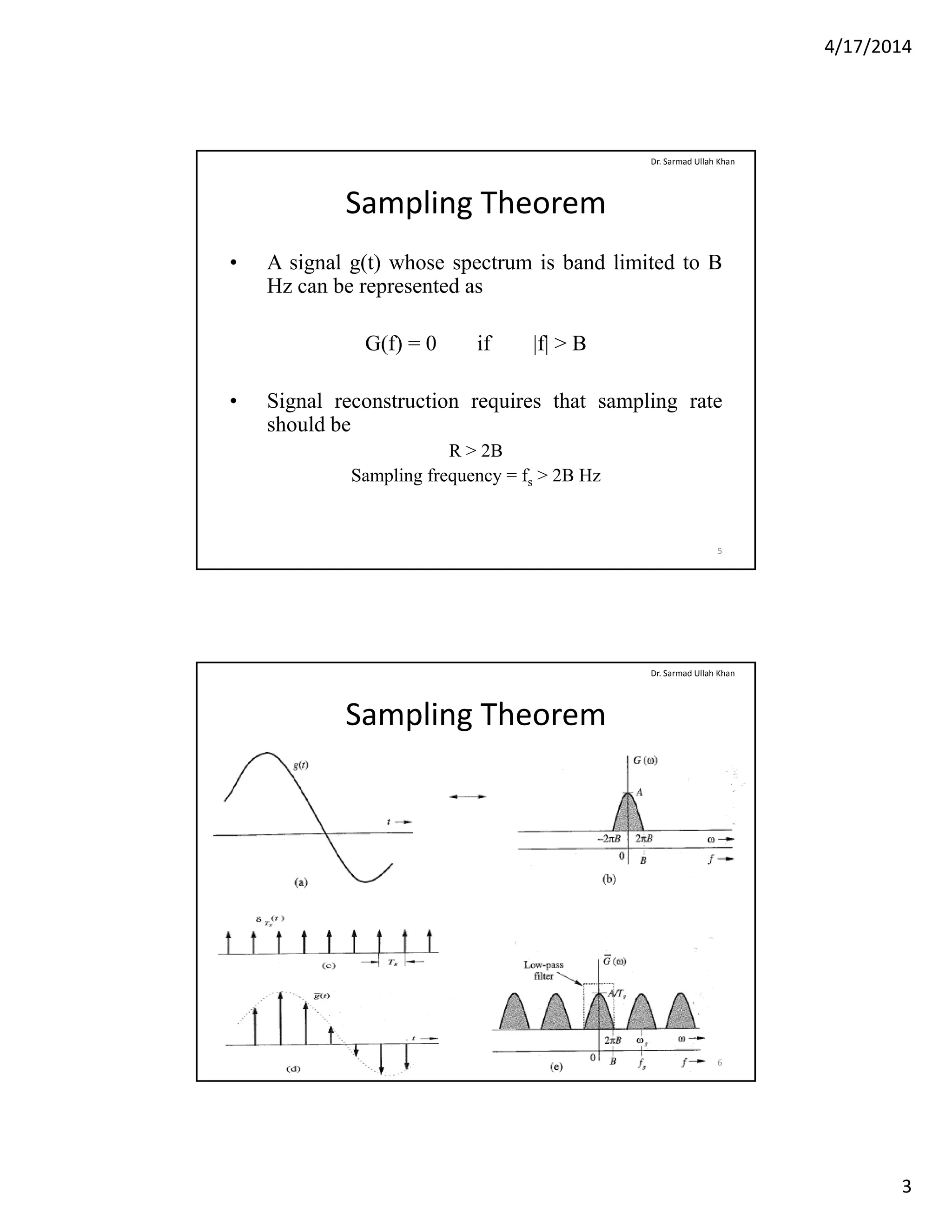
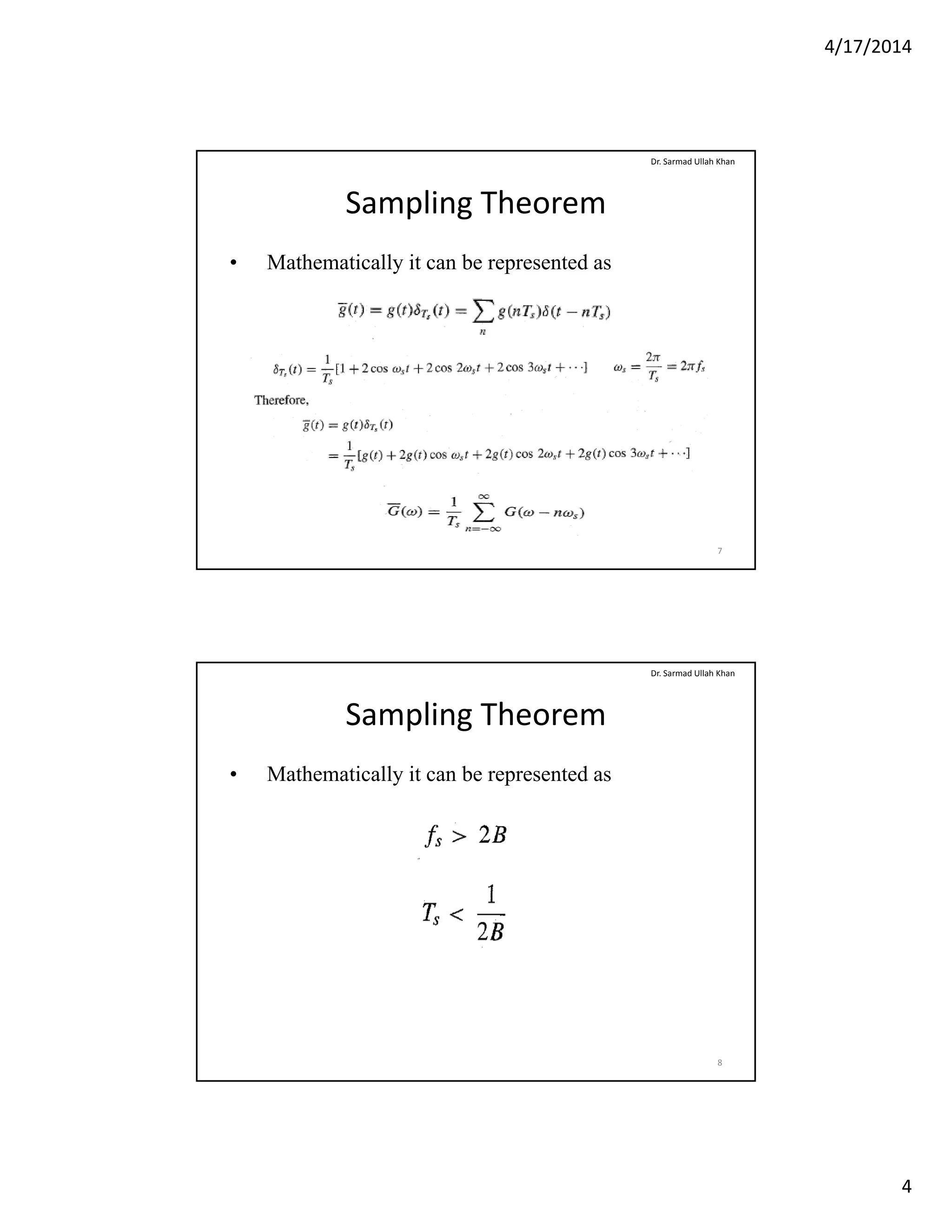
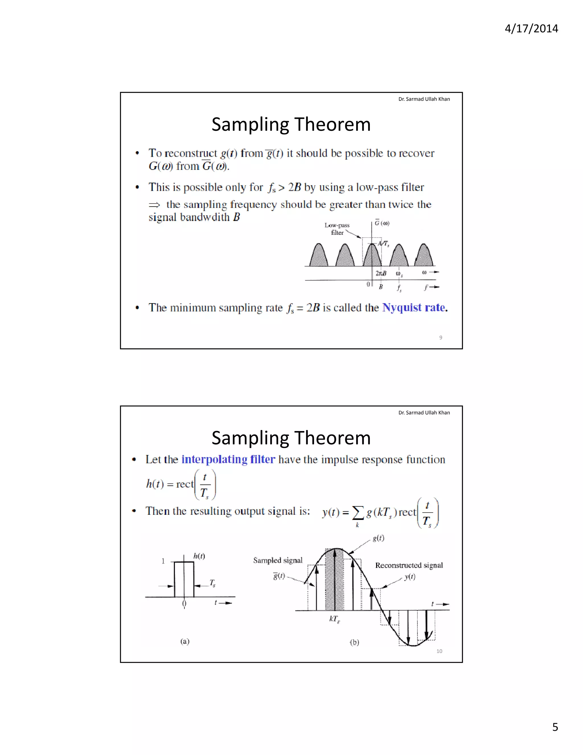
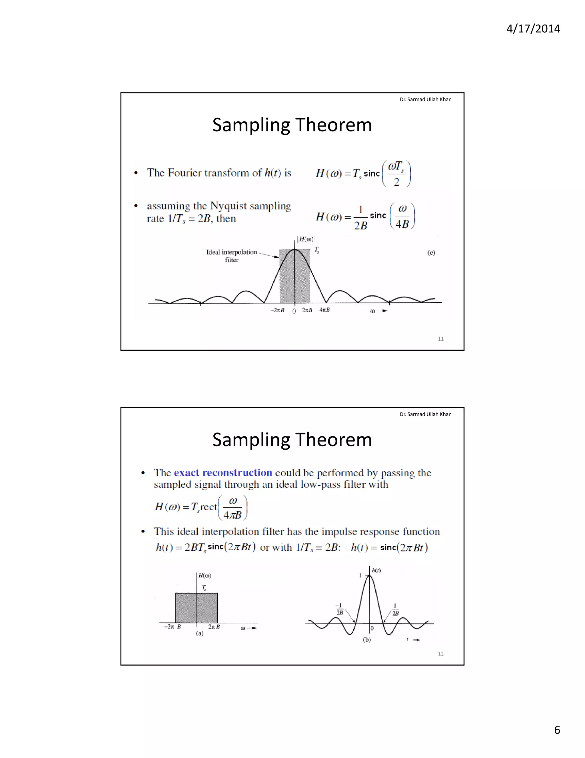
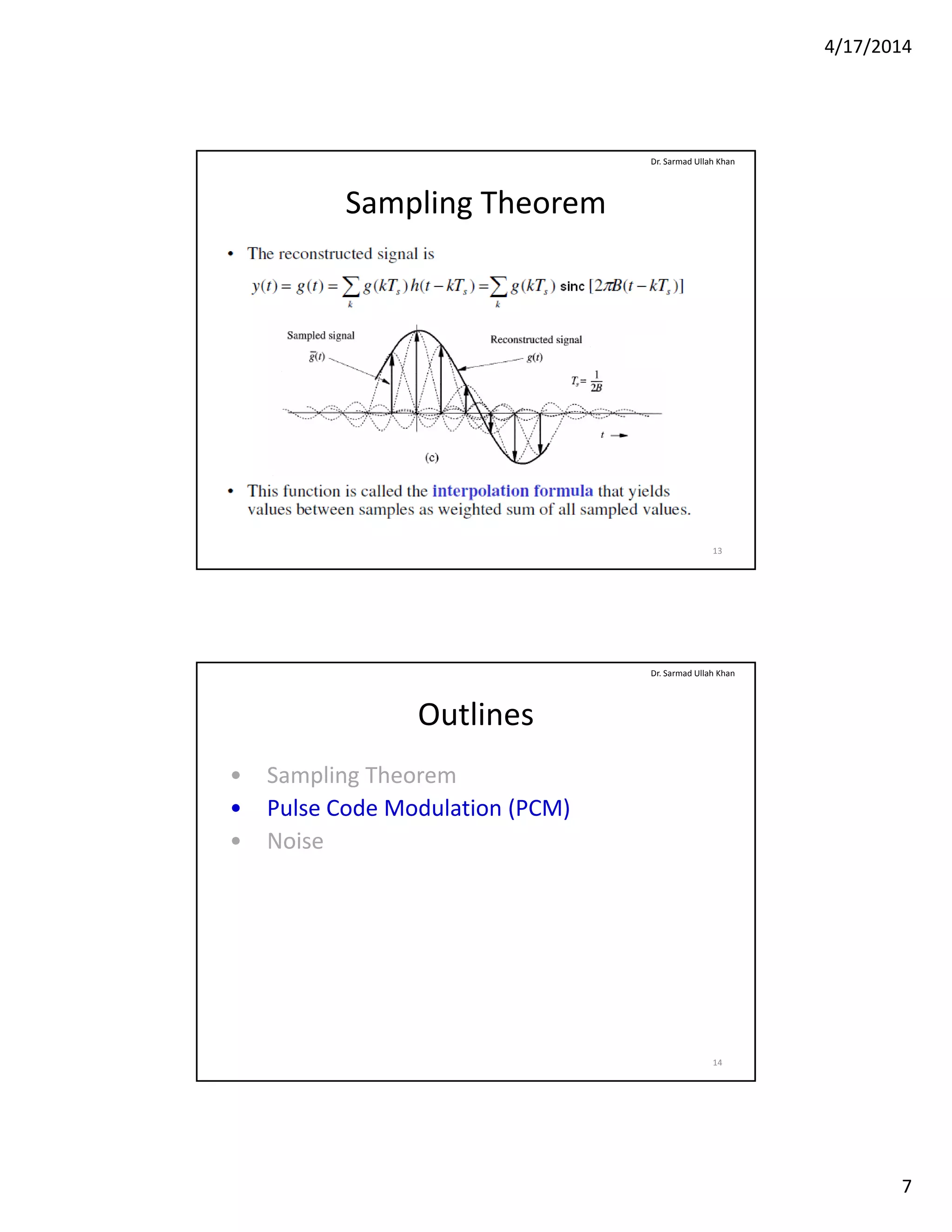
4/17/2014
1
Communication Systems
Instructor: Engr. Dr. Sarmad Ullah Khan
Assistant ProfessorAssistant Professor
Electrical Engineering Department
CECOS University of IT and Emerging Sciences
Sarmad@cecos.edu.pk
Chapter 6
Dr. Sarmad Ullah Khan
Sampling and Analog to Digital
Conversion
2
4/17/2014
2
Outlines
• Sampling Theorem
P l C d M d l ti (PCM)
Dr. Sarmad Ullah Khan
• Pulse Code Modulation (PCM)
• Noise
3
Outlines
• Sampling Theorem
P l C d M d l ti (PCM)
Dr. Sarmad Ullah Khan
• Pulse Code Modulation (PCM)
• Noise
4
4/17/2014
3
Sampling Theorem
• A signal g(t) whose spectrum is band limited to B
Hz can be represented as
Dr. Sarmad Ullah Khan
Hz can be represented as
G(f) = 0 if |f| > B
• Signal reconstruction requires that sampling rate
should beshould be
R > 2B
Sampling frequency = fs > 2B Hz
5
Sampling Theorem
Dr. Sarmad Ullah Khan
6
4/17/2014
4
Sampling Theorem
• Mathematically it can be represented as
Dr. Sarmad Ullah Khan
7
Sampling Theorem
• Mathematically it can be represented as
Dr. Sarmad Ullah Khan
8
4/17/2014
5
Sampling Theorem
• Mathematically it can be represented as
Dr. Sarmad Ullah Khan
9
Sampling Theorem
Dr. Sarmad Ullah Khan
10
4/17/2014
6
Sampling Theorem
Dr. Sarmad Ullah Khan
11
Sampling Theorem
Dr. Sarmad Ullah Khan
12
4/17/2014
7
Sampling Theorem
Dr. Sarmad Ullah Khan
13
Outlines
• Sampling Theorem
P l C d M d l ti (PCM)
Dr. Sarmad Ullah Khan
• Pulse Code Modulation (PCM)
• Noise
14
4/17/2014
8
Pulse Code Modulation
Dr. Sarmad Ullah Khan
15
Pulse Code Modulation
Dr. Sarmad Ullah Khan
16
4/17/2014
9
Pulse Code Modulation
Dr. Sarmad Ullah Khan
17
Pulse Code Modulation
Dr. Sarmad Ullah Khan
18
4/17/2014
10
Outlines
• Sampling Theorem
P l C d M d l ti (PCM)
Dr. Sarmad Ullah Khan
• Pulse Code Modulation (PCM)
• Noise
19
Noise
• In any real physical system, when the signal voltage
arise at the demodulator it will be accompanied by
Dr. Sarmad Ullah Khan
arise at the demodulator, it will be accompanied by
a voltage waveform which varies with time in an
entirely unpredictable manner. This unpredictable
voltage wave form is a random process called noise
20
4/17/2014
11
Noise
• Types of Noise
Most man made electro magnetic noise occurs at
Dr. Sarmad Ullah Khan
Most man made electro-magnetic noise occurs at
frequencies below 500 MHz. The most significant of
these include:
• Hydro lines
• Ignition systems
• Fluorescent lightsFluorescent lights
• Electric motors
Therefore deep space networks are placed out in the
desert, far from these sources of interference.
21
Noise
• There are also a wide range of natural noise sources
which cannot be so easily avoided, namely:
Dr. Sarmad Ullah Khan
y , y
• Atmospheric noise - lighting < 20 MHz
• Solar noise - sun - 11 year sunspot cycle
• Cosmic noise - 8 MHz to 1.5 GHz
• Thermal or Johnson noise. Due to free electrons
striking vibrating ions.
• White noise white noise has a constant spectral• White noise - white noise has a constant spectral
density over a specified range of frequencies.
Johnson noise is an example of white noise.
22
4/17/2014
12
Noise
• Gaussian noise - Gaussian noise is completely
random in nature however, the probability of
Dr. Sarmad Ullah Khan
, p y
any particular amplitude value follows the
normal distribution curve. Johnson noise is
Gaussian in nature.
• Shot noise - bipolar transistors (caused by
random variations in the arrival of electrons or
holes at the output electrodes of an amplifying
device)device)
• Transit time noise - occurs when the electron
transit time across a junction is the same period
as the signal.
23
Noise
• The noise power is given by:
P kTB
Dr. Sarmad Ullah Khan
Pn = kTB
• Where:
• k = Boltzman's constant (1.38 x 10⁻²³ J/K)
• T = temperature in degrees Kelvin
• B = bandwidth in Hz
• If the two signals are completely random with respect
to each other, such as Johnson noise sources, the total
power is the sum of all of the individual powers:
24
4/17/2014
13
Noise
• A Johnson noise of power P = kTB, can be thought of
as a noise voltage applied through a resistor
Dr. Sarmad Ullah Khan
as a noise voltage applied through a resistor,
Thevenin equivalent.
• An example of such a noise source may be a cable or
transmission line. The amount of noise power
transferred from the source to a load, such as an
amplifier input is a function of the source and loadamplifier input, is a function of the source and load
impedances
25
Noise
Dr. Sarmad Ullah Khan
• The rms noise voltage at maximum power transfer is
• Observe what happens if the noise resistance is
resolved into two components
26
4/17/2014
14
Noise
• The terms used to quantify noise :
Si l t i ti I i i h i l
Dr. Sarmad Ullah Khan
• Signal to noise ratio: It is either unit-less or
specified in dB. The S/N ratio may be specified
anywhere within a system.
• Noise Factor (or Noise Ratio):
27
Noise
• This parameter (i.e. Noise Figure ) is specified in all
high performance amplifiers and is measure of how
Dr. Sarmad Ullah Khan
high performance amplifiers and is measure of how
much noise the amplifier itself contributes to the total
noise. In a perfect amplifier or system, NF = 0 dB.
This discussion does not take into account any noise
reduction techniques such as filtering or dynamic
emphasisp
28
4/17/2014
15
Noise
• Friiss' Formula & Amplifier Cascades
It i i t ti t i lifi d t h
Dr. Sarmad Ullah Khan
– It is interesting to examine an amplifier cascade to see how
noise builds up in a large communication system
– Amplifier gain can be defined asp g
29
Noise
• Friiss' Formula & Amplifier Cascades
A d th i f t ( ti ) b itt
Dr. Sarmad Ullah Khan
– And the noise factor (ratio) can be rewritten as
– The output noise power can now be written
30
4/17/2014
16
Noise
• Friiss' Formula & Amplifier Cascades
F thi b th t th i t i i i d b
Dr. Sarmad Ullah Khan
– From this we observe that the input noise is increased by
the noise ratio and amplifier gain as it passes through the
amplifier. A noiseless amplifier would have a noise ratio
(factor) of 1 or noise figure of 0 dB. In this case, the input
noise would only be amplified by the gain since the
amplifier would not contribute noise
31
Friiss' Formula

Chapter 6

  • 1.
    4/17/2014 1 Communication Systems Instructor: Engr. Dr.Sarmad Ullah Khan Assistant ProfessorAssistant Professor Electrical Engineering Department CECOS University of IT and Emerging Sciences Sarmad@cecos.edu.pk Chapter 6 Dr. Sarmad Ullah Khan Sampling and Analog to Digital Conversion 2
  • 2.
    4/17/2014 2 Outlines • Sampling Theorem Pl C d M d l ti (PCM) Dr. Sarmad Ullah Khan • Pulse Code Modulation (PCM) • Noise 3 Outlines • Sampling Theorem P l C d M d l ti (PCM) Dr. Sarmad Ullah Khan • Pulse Code Modulation (PCM) • Noise 4
  • 3.
    4/17/2014 3 Sampling Theorem • A signalg(t) whose spectrum is band limited to B Hz can be represented as Dr. Sarmad Ullah Khan Hz can be represented as G(f) = 0 if |f| > B • Signal reconstruction requires that sampling rate should beshould be R > 2B Sampling frequency = fs > 2B Hz 5 Sampling Theorem Dr. Sarmad Ullah Khan 6
  • 4.
    4/17/2014 4 Sampling Theorem • Mathematically itcan be represented as Dr. Sarmad Ullah Khan 7 Sampling Theorem • Mathematically it can be represented as Dr. Sarmad Ullah Khan 8
  • 5.
    4/17/2014 5 Sampling Theorem • Mathematically itcan be represented as Dr. Sarmad Ullah Khan 9 Sampling Theorem Dr. Sarmad Ullah Khan 10
  • 6.
  • 7.
    4/17/2014 7 Sampling Theorem Dr. Sarmad Ullah Khan 13 Outlines • Sampling Theorem Pl C d M d l ti (PCM) Dr. Sarmad Ullah Khan • Pulse Code Modulation (PCM) • Noise 14
  • 8.
  • 9.
  • 10.
    4/17/2014 10 Outlines • Sampling Theorem Pl C d M d l ti (PCM) Dr. Sarmad Ullah Khan • Pulse Code Modulation (PCM) • Noise 19 Noise • In any real physical system, when the signal voltage arise at the demodulator it will be accompanied by Dr. Sarmad Ullah Khan arise at the demodulator, it will be accompanied by a voltage waveform which varies with time in an entirely unpredictable manner. This unpredictable voltage wave form is a random process called noise 20
  • 11.
    4/17/2014 11 Noise • Types ofNoise Most man made electro magnetic noise occurs at Dr. Sarmad Ullah Khan Most man made electro-magnetic noise occurs at frequencies below 500 MHz. The most significant of these include: • Hydro lines • Ignition systems • Fluorescent lightsFluorescent lights • Electric motors Therefore deep space networks are placed out in the desert, far from these sources of interference. 21 Noise • There are also a wide range of natural noise sources which cannot be so easily avoided, namely: Dr. Sarmad Ullah Khan y , y • Atmospheric noise - lighting < 20 MHz • Solar noise - sun - 11 year sunspot cycle • Cosmic noise - 8 MHz to 1.5 GHz • Thermal or Johnson noise. Due to free electrons striking vibrating ions. • White noise white noise has a constant spectral• White noise - white noise has a constant spectral density over a specified range of frequencies. Johnson noise is an example of white noise. 22
  • 12.
    4/17/2014 12 Noise • Gaussian noise- Gaussian noise is completely random in nature however, the probability of Dr. Sarmad Ullah Khan , p y any particular amplitude value follows the normal distribution curve. Johnson noise is Gaussian in nature. • Shot noise - bipolar transistors (caused by random variations in the arrival of electrons or holes at the output electrodes of an amplifying device)device) • Transit time noise - occurs when the electron transit time across a junction is the same period as the signal. 23 Noise • The noise power is given by: P kTB Dr. Sarmad Ullah Khan Pn = kTB • Where: • k = Boltzman's constant (1.38 x 10⁻²³ J/K) • T = temperature in degrees Kelvin • B = bandwidth in Hz • If the two signals are completely random with respect to each other, such as Johnson noise sources, the total power is the sum of all of the individual powers: 24
  • 13.
    4/17/2014 13 Noise • A Johnsonnoise of power P = kTB, can be thought of as a noise voltage applied through a resistor Dr. Sarmad Ullah Khan as a noise voltage applied through a resistor, Thevenin equivalent. • An example of such a noise source may be a cable or transmission line. The amount of noise power transferred from the source to a load, such as an amplifier input is a function of the source and loadamplifier input, is a function of the source and load impedances 25 Noise Dr. Sarmad Ullah Khan • The rms noise voltage at maximum power transfer is • Observe what happens if the noise resistance is resolved into two components 26
  • 14.
    4/17/2014 14 Noise • The termsused to quantify noise : Si l t i ti I i i h i l Dr. Sarmad Ullah Khan • Signal to noise ratio: It is either unit-less or specified in dB. The S/N ratio may be specified anywhere within a system. • Noise Factor (or Noise Ratio): 27 Noise • This parameter (i.e. Noise Figure ) is specified in all high performance amplifiers and is measure of how Dr. Sarmad Ullah Khan high performance amplifiers and is measure of how much noise the amplifier itself contributes to the total noise. In a perfect amplifier or system, NF = 0 dB. This discussion does not take into account any noise reduction techniques such as filtering or dynamic emphasisp 28
  • 15.
    4/17/2014 15 Noise • Friiss' Formula& Amplifier Cascades It i i t ti t i lifi d t h Dr. Sarmad Ullah Khan – It is interesting to examine an amplifier cascade to see how noise builds up in a large communication system – Amplifier gain can be defined asp g 29 Noise • Friiss' Formula & Amplifier Cascades A d th i f t ( ti ) b itt Dr. Sarmad Ullah Khan – And the noise factor (ratio) can be rewritten as – The output noise power can now be written 30
  • 16.
    4/17/2014 16 Noise • Friiss' Formula& Amplifier Cascades F thi b th t th i t i i i d b Dr. Sarmad Ullah Khan – From this we observe that the input noise is increased by the noise ratio and amplifier gain as it passes through the amplifier. A noiseless amplifier would have a noise ratio (factor) of 1 or noise figure of 0 dB. In this case, the input noise would only be amplified by the gain since the amplifier would not contribute noise 31 Friiss' Formula