Downloaded 18 times

(
)](Re[)( tt FMFM
](https://image.slidesharecdn.com/chapter5-140514151428-phpapp02/85/Chapter-5-9-320.jpg)
![3/23/2014
11
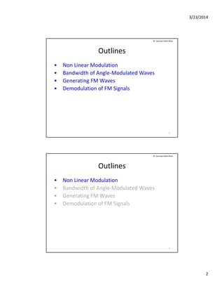
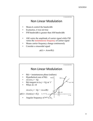
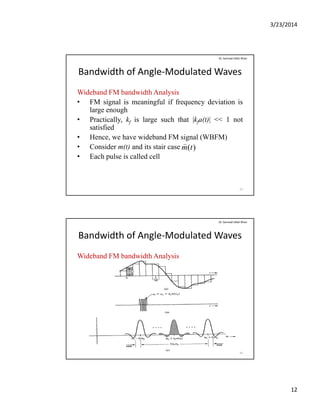
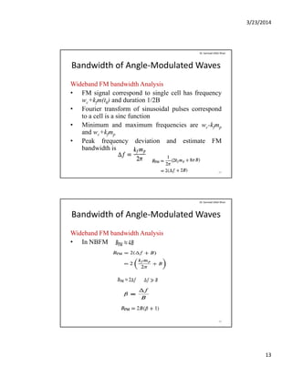
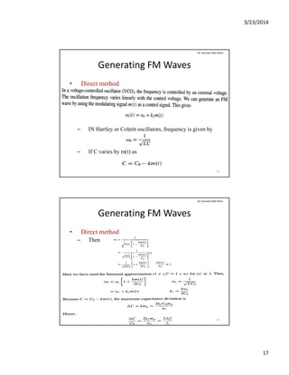
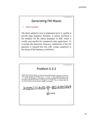
Bandwidth of Angle‐Modulated Waves
• Because n! increases much faster than |kfa(t)|n
Dr. Sarmad Ullah Khan
Narrow Band Angle Modulation
• When kf is very small such that
|k (t)| << 1
0
!
)(
n
tak nn
f
|kfa(t)| << 1
then
• This approximation is linear like AM expression
21
]sin)([cos)( ttaktAt cfcFM
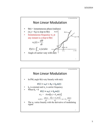
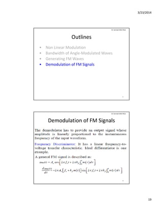
Bandwidth of Angle‐Modulated Waves
• Bandwidth of a(t) is B, bandwidth of is 2B
• Narrow band PM signal is approximated as
Dr. Sarmad Ullah Khan
)(tFM
• Narrow band PM signal is approximated as
• NBPM has approximate bandwidth of 2B
]sin)([cos)( ttmktAt cPcPM
22](https://image.slidesharecdn.com/chapter5-140514151428-phpapp02/85/Chapter-5-11-320.jpg)

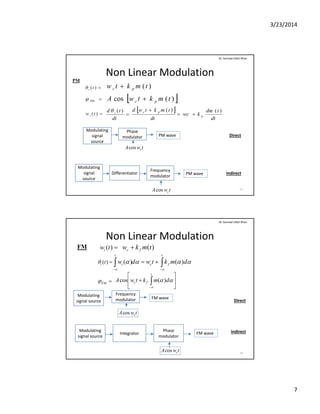
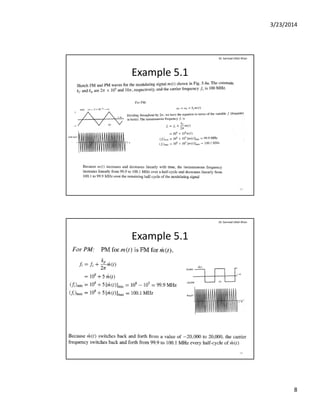
The document discusses angle modulation and demodulation in communication systems, focusing on non-linear modulation, bandwidth analysis, and methods for generating and demodulating FM signals. Key topics include how frequency and phase modulation work, the differences in bandwidth between amplitude modulation (AM) and frequency modulation (FM), and practical approaches to FS wave generation using direct and indirect methods. Additionally, it outlines the challenges related to bandwidth analysis of angle-modulated waves and the necessary techniques for demodulating FM signals.